
User Manual
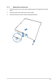
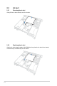
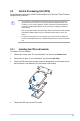
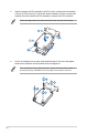
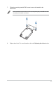
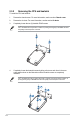
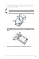
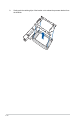
Table Of Contents
- Safety information
- Chapter 1: Product Introduction
- Chapter 2: Hardware Information
- 2.1 Chassis cover
- 2.2 Air duct
- 2.3 Central Processing Unit (CPU)
- 2.4 System memory
- 2.5 Storage devices
- 2.5.1 Installing an E1.S module (optional)
- 2.5.2 Removing an E1.S module (optional)
- 2.5.3 Installing an external 2.5” storage device (on selected models)
- 2.5.4 Removing an external 2.5” storage device (on selected models)
- 2.5.5 Installing an internal 2.5” storage device (optional on selected models)
- 2.5.6 Removing an internal 2.5” storage device (optional on selected models)
- 2.6 Expansion slot
- 2.7 Cable connections
- 2.8 Removable/optional components
- 2.9 Rail Kit Options
- Chapter 3: Motherboard Information
- Chapter 4: BIOS Setup
- 4.1 Managing and updating your BIOS
- 4.2 BIOS setup program
- 4.3 Main menu
- 4.4 Performance Tuning menu
- 4.5 Advanced menu
- 4.5.1 Trusted Computing
- 4.5.2 ACPI Settings
- 4.5.3 Redfish Host Interface Settings
- 4.5.4 Onboard LAN Configuration
- 4.5.5 UEFI Variables Protection
- 4.5.6 Serial Port Console Redirection
- 4.5.7 SIO Configuration
- 4.5.8 PCI Subsystem Settings
- 4.5.9 USB Configuration
- 4.5.10` Network Stack Configuration
- 4.5.11 NVMe Configuration
- 4.5.12 APM Configuration
- 4.5.13 Tls Auth Configuration
- 4.5.14 Intel(R) Virtual RAID on CPU
- 4.5.15 Third-party UEFI driver configurations
- 4.6 Platform Configuration menu
- 4.7 Socket Configuration menu
- 4.8 Security menu
- 4.9 Boot menu
- 4.10 Tool menu
- 4.11 Event Logs menu
- 4.12 Server Mgmt menu
- 4.13 Exit menu
- Appendix

2-9
5. Push the lock latches inwards on all four corners of the heatsink so that the heatsink
and CPU assembly is detached from the CPU socket (A), then lift and remove the
heatsink and CPU assembly (B).
Please hold the front and rear short sides of the heatsink when removing the heatsink.
Ensure to replace the PNP cap once the heatsink assembly is removed.
6. Flip the heatsink assembly over, then locate the thermal interface material (TIM) break
lever. Release the TIM break lever from the latch and lift the TIM break lever to release
the CPU.
7. Hold the CPU by the edges and remove it from the carrier and place it aside.