
User Manual
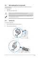
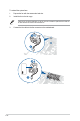
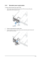
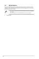

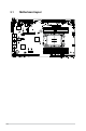
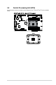
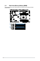
Table Of Contents
- Safety information
- Chapter 1: Product Introduction
- Chapter 2: Hardware Information
- 2.1 Chassis cover
- 2.2 Air duct
- 2.3 Central Processing Unit (CPU)
- 2.4 System memory
- 2.5 Storage devices
- 2.5.1 Installing an E1.S module (optional)
- 2.5.2 Removing an E1.S module (optional)
- 2.5.3 Installing an external 2.5” storage device (on selected models)
- 2.5.4 Removing an external 2.5” storage device (on selected models)
- 2.5.5 Installing an internal 2.5” storage device (optional on selected models)
- 2.5.6 Removing an internal 2.5” storage device (optional on selected models)
- 2.6 Expansion slot
- 2.7 Cable connections
- 2.8 Removable/optional components
- 2.9 Rail Kit Options
- Chapter 3: Motherboard Information
- Chapter 4: BIOS Setup
- 4.1 Managing and updating your BIOS
- 4.2 BIOS setup program
- 4.3 Main menu
- 4.4 Performance Tuning menu
- 4.5 Advanced menu
- 4.5.1 Trusted Computing
- 4.5.2 ACPI Settings
- 4.5.3 Redfish Host Interface Settings
- 4.5.4 Onboard LAN Configuration
- 4.5.5 UEFI Variables Protection
- 4.5.6 Serial Port Console Redirection
- 4.5.7 SIO Configuration
- 4.5.8 PCI Subsystem Settings
- 4.5.9 USB Configuration
- 4.5.10` Network Stack Configuration
- 4.5.11 NVMe Configuration
- 4.5.12 APM Configuration
- 4.5.13 Tls Auth Configuration
- 4.5.14 Intel(R) Virtual RAID on CPU
- 4.5.15 Third-party UEFI driver configurations
- 4.6 Platform Configuration menu
- 4.7 Socket Configuration menu
- 4.8 Security menu
- 4.9 Boot menu
- 4.10 Tool menu
- 4.11 Event Logs menu
- 4.12 Server Mgmt menu
- 4.13 Exit menu
- Appendix

3-3
Layout contents
Jumpers Page
1. Clear RTC RAM (3-pin CLRTC1) 3-7
2. VGA controller setting (3-pin VGA_SW1) 3-8
3. Baseboard Management Controller setting (3-pin BMC_EN1) 3-8
4. DMLAN setting (3-pin DM_IP_SEL1) 3-9
5. IPMI SW setting (3-pin IPMI_SW1) 3-9
6. LAN Controller settings (3-pin LAN_SW1-2) 3-10
7. Smart Ride Through (SmaRT) setting (3-pin SMART_PSU1) 3-10
8. Heatsink Type setting (3-pin HS_TYPE1) 3-11
9. ME firmware force recovery setting (3-pin ME_RCVR1) 3-11
10. PCH_MFG1 jumper (3-pin PCH_MFG1) 3-12
11. RBT NCSI Source jumper (3-pin RMII_SEL1) 3-13
Onboard LEDs Page
1. Standby Power LED (SBPWR1) 3-13
2. Baseboard Management Controller LED (BMCLED1) 3-13
3. Message LED (MESLED1) 3-14
4. CATT ERR LED (CATTERR1) 3-14
5. DIMM LED (DIMMLED1) 3-15
6. Location LED (LOCLED1) 3-15
7. Q-Code LED (PORT80_LED1) 3-16
Central Processing Unit (CPU)
Page
1. LGA 4677 sockets (CPU1) 3-5
Dual Inline Memory Module (DIMM)
Page
1. DDR5 sockets 3-6