
User Manual
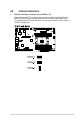
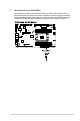
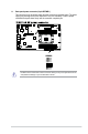
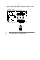
Table Of Contents
- Safety information
- Chapter 1: Product Introduction
- Chapter 2: Hardware Information
- 2.1 Chassis cover
- 2.2 Air duct
- 2.3 Central Processing Unit (CPU)
- 2.4 System memory
- 2.5 Storage devices
- 2.5.1 Installing an E1.S module (optional)
- 2.5.2 Removing an E1.S module (optional)
- 2.5.3 Installing an external 2.5” storage device (on selected models)
- 2.5.4 Removing an external 2.5” storage device (on selected models)
- 2.5.5 Installing an internal 2.5” storage device (optional on selected models)
- 2.5.6 Removing an internal 2.5” storage device (optional on selected models)
- 2.6 Expansion slot
- 2.7 Cable connections
- 2.8 Removable/optional components
- 2.9 Rail Kit Options
- Chapter 3: Motherboard Information
- Chapter 4: BIOS Setup
- 4.1 Managing and updating your BIOS
- 4.2 BIOS setup program
- 4.3 Main menu
- 4.4 Performance Tuning menu
- 4.5 Advanced menu
- 4.5.1 Trusted Computing
- 4.5.2 ACPI Settings
- 4.5.3 Redfish Host Interface Settings
- 4.5.4 Onboard LAN Configuration
- 4.5.5 UEFI Variables Protection
- 4.5.6 Serial Port Console Redirection
- 4.5.7 SIO Configuration
- 4.5.8 PCI Subsystem Settings
- 4.5.9 USB Configuration
- 4.5.10` Network Stack Configuration
- 4.5.11 NVMe Configuration
- 4.5.12 APM Configuration
- 4.5.13 Tls Auth Configuration
- 4.5.14 Intel(R) Virtual RAID on CPU
- 4.5.15 Third-party UEFI driver configurations
- 4.6 Platform Configuration menu
- 4.7 Socket Configuration menu
- 4.8 Security menu
- 4.9 Boot menu
- 4.10 Tool menu
- 4.11 Event Logs menu
- 4.12 Server Mgmt menu
- 4.13 Exit menu
- Appendix

3-25
11. Back panel power connector (8-pin BPPWR1)
This connector is for the power supply plug that connects to the back panel. The power
supply plug is designed to fit this connector in only one orientation. Find the proper
orientation and push down firmly until the connector completely fits.
DO NOT connect VGA cards to these connectors. Doing so may cause system boot errors
and permanent damage to your motherboard or device.