ESC300 G4 Workstation User Guide
E13698 Revised Edition V2 December 2017 Copyright © 2017 ASUSTeK COMPUTER INC. All Rights Reserved. No part of this manual, including the products and software described in it, may be reproduced, transmitted, transcribed, stored in a retrieval system, or translated into any language in any form or by any means, except documentation kept by the purchaser for backup purposes, without the express written permission of ASUSTeK COMPUTER INC. (“ASUS”).
Contents Notices ........................................................................................................................ vi Federal Communications Commission Statement...........................................vi REACH .......................................................................................................vii Safety information..................................................................................................... viii Electrical Safety.........................
Contents Chapter 3: Motherboard Information 3.1 Motherboard layout..................................................................................... 3-2 Chapter 4: BIOS Setup 4.1 Knowing BIOS............................................................................................. 4-2 4.2 BIOS setup program................................................................................... 4-3 4.2.1 4.2.2 Advanced Mode...........................................................................
Contents Chapter 5: RAID Configuration 5.1 5.2 RAID configurations................................................................................... 5-2 5.1.1 RAID definitions........................................................................... 5-2 5.1.2 Installing Serial ATA hard disks................................................... 5-3 5.1.3 Intel® Rapid Storage Technology in UEFI BIOS........................... 5-3 5.1.4 Intel® Rapid Storage Technology Option ROM utility...............
Notices Federal Communications Commission Statement This device complies with Part 15 of the FCC Rules. Operation is subject to the following two conditions: • This device may not cause harmful interference, and • This device must accept any interference received including interference that may cause undesired operation. This equipment has been tested and found to comply with the limits for a Class B digital device, pursuant to Part 15 of the FCC Rules.
REACH Complying with the REACH (Registration, Evaluation, Authorization, and Restriction of Chemicals) regulatory framework, we published the chemical substances in our products at ASUS website at http://csr.asus.com/english/REACH.htm. ASUS Recycling/Takeback Services ASUS recycling and takeback programs come from our commitment to the highest standards for protecting our environment.
Safety information Electrical Safety • Before installing or removing signal cables, ensure that the power cables for the system unit and all attached devices are unplugged. • To prevent electrical shock hazard, disconnect the power cable from the electrical outlet before relocating the system. • When adding or removing any additional devices to or from the system, contact a qualified service technician or your dealer.
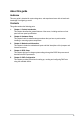
About this guide Audience This user guide is intended for system integrators, and experienced users with at least basic knowledge of configuring a server. Contents This guide contains the following parts: 1. Chapter 1: Product Introduction This chapter describes the general features of the server, including sections on front panel and rear panel specifications. 2.
Conventions used in this guide To ensure that you perform certain tasks properly, take note of the following symbols used throughout this manual. DANGER/WARNING: Information to prevent injury to yourself when trying to complete a task. CAUTION: Information to prevent damage to the components when trying to complete a task IMPORTANT: Instructions that you MUST follow to complete a task. NOTE: Tips and additional information to help you complete a task.
Chapter 1: Product Introduction Product Introduction This chapter describes the general features of the server, including sections on front panel and rear panel specifications.
1.1 System package contents Check your system package for the following items. Model Name ESC300 G4 Accessories 1 x ESC300 G4 Support CD 1 x Windows 10 and Windows 7 Professional Recovery DVD (for OS bundled SKU) 1 x AC Power Cable 1 x COM port Cable Optional Items Smart Card Reader Anti-Virus CD pack DVD-RW Keyboard and mouse If any of the above items is damaged or missing, contact your retailer. 1.
1.3 ESC300 G4 specifications summary The ASUS ESC300 G4 is a workstation featuring the ASUS E3-Pro V5 server board. LGA1151 socket for Intel® Xeon® E3-1200 v6/v5 series, 7th/6th Generation Intel® CoreTM, Pentium®, and Celeron® Processors Processor / System Bus Supports 14nm CPU Supports Intel® Turbo Boost Technology 2.0* * Intel® Turbo Boost Technology 2.0 support depends on the CPU types. ** Refer to www.asus.com for Intel® CPU support list.
ESC300 G4 specifications summary 1 x PS/2 keyboard (purple) 1 x PS/2 mouse (green) 1 x LAN (RJ45) port(s) Rear I/O 4 x USB 3.0 4 x USB 2.0 3 x Audio jack(s) 1 x M.2 Socket 3 for M Key, type 2242/2260/2280 devices 1 x COM port Onboard I/O 1 x S/PDIF out header 2 x USB 3.0 (front) 2 x USB 2.0 (front) (optional switch to card reader) Windows® 10 (support Preload OS) Windows® 7 RS2 32bit/64bit OS Support * Refer to http://www.asus.com/ for the latest OS support.
1.4 Front panel features The ESC300 G4 workstation features a simple yet stylish front panel design. The power and reset buttons, LED indicators, optical drive, and USB ports are all conveniently located at the front panel for easy access. Optical Drive (Optional) Empty 5.25-inch bay Card reader (optional)* Smart Card SD/MMC/MS USB 3.0 ports USB 2.0 ports* Headphone port Microphone port Power LED Reset button Power button HDD access LED * The USB 2.
1.5 Rear panel features The rear panel includes a slot for the motherboard rear I/O ports, expansion slots, a vent for the system fan, and the power supply module. Single power supply Power connector PS/2 Mouse port PS/2 keyboard port USB 2.0 ports 120 mm x 120 mm system fan vents USB 3.0 USB 3.0 ports LAN port Audio ports USB 3.
1.6 Internal features The ASUS ESC300 G4 Pedestal server system includes the basic components as shown: 1. Power supply unit 2. 120 mm x 120 mm system fan (optional) 3. ASUS E3-PRO V5 Server Board 4. Expansion card locks 5. Optical drive (Optional) 6. 1 x 5.25-inch drive bay 7. Front I/O board (hidden) 8. 3 x 3.5-inch Internal HDD bays 9. 1 x 2.5-inch Internal HDD/SSD bay Turn off the system power and detach the power supply before removing or replacing any system component.
1.7 LED information 1.7.1 Front panel LEDs SD/MMC/MS Smart Card HDD Access LED Power LED SD/MMC/MS Smart Card LED Icon HDMI Display/Port Display status Power LED ON HDD Access LED OFF Blinking 10 USB 3.1 1.7.2 Description SPDIF OUT System power ON No activity Read/write data into the HDD Rear panel LEDs DVI VGA OUT USB 3.0 ACT/LINK LED SPEED LED USB 3.0 USB 3.0 MIC IN LINE OUT LINE IN USB 3.
Chapter 2: Hardware Setup Hardware Setup This chapter lists the hardware setup procedures that you have to perform when installing system components. It includes description of the jumpers and connectors on the motherboard.
2.1 Chassis cover 2.1.1 Removing the side cover • Ensure that you unplug the power cord before removing the side cover. • Take extra care when removing the side cover. Keep your fingers from components inside the chassis that can cause injury, such as the CPU fan, rear fan, and other sharp-edged parts. • The images of the barebone server shown in this section are for reference purposes only and may not exactly match the model you purchase. To remove the side cover: 1.
3. Slightly pull the side cover toward the rear just enough to detach it from the chassis. 4. Remove the cover and set it aside.
2.2 CPU installation This motherboard comes with a surface mount LGA1151 socket designed for Intel® Xeon® E3-1200 v6/v5 series, 7th/6th Generation Intel® Core™, Pentium®, and Celeron® processors. Unplug all power cables before installing the CPU. 2-4 • Ensure that you install the correct CPU designed for the LGA1151 socket only. DO NOT install a CPU designed for LGA1150, LGA1155 and LGA1156 sockets on the LGA1151 socket.
Load lever Retention tab CPU notches Gold triangle mark Alignment key Alignment key Load plate Load lever Load lever Retention tab Retention lock ASUS ESC300 G4 2-5
2.3 CPU heatsink and fan assembly installation Apply the Thermal Interface Material to the CPU heatsink and CPU before you install the heatsink and fan, if necessary.
2.4 System memory The motherboard comes with four DDR 4 (Double Data Rate 4) Dual Inline Memory Modules (DIMM) slots. A DDR4 module is notched differently from a DDR, DDR2 or DDR3 module. DO NOT install a DDR, DDR2 or DDR3 memory module to the DDR4 slot.
Memory configurations You may install 8 GB and 16 GB unbuffered and ECC and non‑ECC DDR4 DIMMs into the DIMM sockets. • You may install varying memory sizes in Channel A and Channel B. The system maps the total size of the lower-sized channel for the dual-channel configuration. Any excess memory from the higher-sized channel is then mapped for single-channel operation. • Always install DIMMs with the same CAS latency.
2.4.1 Installing a DIMM on a single clip DIMM socket 1. Unlock a DIMM socket by pressing the retaining clip outward. 2. Align a DIMM on the socket such that the notch on the DIMM matches the DIMM slot key on the socket. DIMM notch DIMM slot key Unlocked retaining clip A DIMM is keyed with a notch so that it fits in only one direction. DO NOT force a DIMM into a socket in the wrong direction to avoid damaging the DIMM. 3.
2.5 Front panel cover Before you can install a 5.25-inch drive, you should first remove the front panel cover. Ensure to unplug the power cable before installing or removing any system components. Failure to do so may cause damage to the motherboard and other system components! 2.5.1 Removing the front panel cover To remove the front panel cover: 1. Locate the front panel assembly lock then slide it outward to unlock the latches that secures the front panel cover to the chassis. Assembly lock 2.
2.6 5.25-inch drives This system comes with three 5.25-inch drive bays located on the upper front section of the chassis. If your system came with an optical drive, the optical drive occupies the topmost bay (1). The lower bays (2 and 3) are available for additional 5.25-inch optical, zip, or floppy disk drives. Installing a 5.25-inch drive To install a 5.25-inch drive: 1. Remove the front panel cover. Refer to the Removing the front panel cover section for more information. 2.
4. Prepare the 5.25-inch drive. 5. Insert and carefully push the drive into the bay until its screw holes align with the holes on the bay. 6. Push the bay locks to secure the drive in place. Bay locks 7. Connect the SATA cable to the SATA connector of the drive. 8. Connect a SATA power cable from the power supply to the power connector of the drive. 9. Reinstall the front panel cover.
2.7 Hard disk drives (HDD) The server system supports three (3) 3.5-inch Serial ATA hard disk drives via the hard disk drive bays and one 2.5-inch HDD/SSD drive at the bottom of the HDD cage. Installing 3.5-inch HDDs To install 3.5-inch Serial ATA hard disk drives: 1. Remove the side cover of the chassis. Refer to the Removing the side cover section for more information. 2. Prepare the 3.5-inch HDD and the bundled set of screws. 3.
2-14 5. Secure the 3.5-inch HDD to the HDD cage using the bundled set of screws. 6. Swing the HDD cage inwards until it clicks back into place. 7. Connect the SATA cable and SATA power cable to the 3.5-inch HDD.
Installing 2.5-inch HDD/SSD To install a 2.5-inch HDD/SSD: 1. Remove the side cover of the chassis. Refer to the Removing the side cover section for more information. 2. Prepare the 2.5-inch HDD/SDD and the bundled set of screws. 3. Lay the system on its side on a flat and stable surface. 4. Locate the HDD cage lock, press it up (A), then swing the HDD cage outwards (B). 5. Align and insert the 2.5-inch HDD/SSD into the drive bay as shown.
2-16 6. Secure the 2.5-inch HDD/SSD to the HDD cage using the bundled set of screws. 7. Swing the HDD cage inwards until it clicks back into place. 8. Connect a SATA cable and a SATA power cable to the 2.5-inch HDD/SSD.
2.8 Expansion slots Unplug the power cord before adding or removing expansion cards. Failure to do so may cause you physical injury and damage motherboard components. KBMS CPU_FAN DIGI +VRM EATX12V CHA_FAN1 2280 2260 2242 PCIEX1_1 E3-PRO V5 RTL 8111H EATXPWR SATA6G_2 M.
2.8.1 Installing an expansion card To install an expansion card: 1. Lay the system on its side on a flat, stable surface. 2. Press the PCI-E latch (A), hold it by its edge then lift it towards the rear (B). Edge of the PCI-E latch PCI-E latch 3. Remove the screw (A) that secures the metal bracket to the chassis then remove the metal bracket (B).
4. Align and insert the expansion card into the PCI-E slot. 5. Lift the PCI-E latch inwards until it clicks into place securing the expansion card to the chassis. Expansion card PCI-E slot PCI-E latch 6. (Optional) Replace the screw of the metal bracket.
2.8.2 Configuring an expansion card VGA configuration PCI Express operating mode PCIe 3.0 x16_1 (gray) PCIe 3.0 x16_2 Single VGA/PCIe card x16 (Recommended for single VGA card) N/A Dual VGA/PCIe cards x16 x4 • In single VGA card mode, use the PCIe 3.0 x16_1 slot (gray) for a PCI Express x16 graphics card to get better performance. • We recommend that you provide sufficient power when running CrossFireX™ mode.
2.8.3 Installing M.2 (NGFF) cards To install an M.2 card: 1. Locate the M.2 connector (M.2(SOCKET3)) on the motherboard. 2. Remove the screw on the stand screw. 3. Prepare the M.2 card. 4. Align and insert the M.2 card into the M.2 connector (M.2(SOCKET3)). 5. Secure the M.2 card with the screw you removed in step 2. Screw NGFF1 Screw hole Stand screw E3-PRO V5 • Please pay attention when removing the screw, the stand screw might be removed together with it. • Ensure that the M.
2.9 System fan This section describes how to remove the system fan in the event that you need to install or remove previously installed or new system components, or when the system fan needs to be replaced because it was damaged or became defective. To remove the system fan: 1. Disconnect the system fan cable from the CHA_FAN1 connector on the motherboard. 2. Remove the four system fan screws at the rear panel. Keep the screws for later use.
2.10 Motherboard rear and audio connection 1 2 7 8 3 4 6 5 Rear panel connectors 1. PS/2 Mouse port (green) 5. Microphone port (pink)** 2. LAN (RJ-45) port* 6. USB 3.0 ports 3. Line In port (light blue)** 7. USB 2.0 ports 4. Line Out port (lime)** 8. PS/2 keyboard port (purple) * and **: Refer to the tables on the next page for LAN port LEDs and audio port definitions. • Due to USB 3.0 controller limitations, USB 3.
** Audio 2.1, 4.1, 5.1 or 7.1-channel configuration Port Light Blue (Rear panel) Lime (Rear panel) Pink (Rear panel) Lime (Front panel) 2-24 Headset 2.1-channel 4.1-channel 5.1-channel 7.
Chapter 3: Motherboard Information Motherboard Information This chapter includes the motherboard layout and brief descriptions of the jumpers and internal connectors.
3.1 Motherboard layout 1 2 1 3 4 21.8cm(8.6in) KBMS CPU_FAN DIGI +VRM EATX12V 16 2280 2260 2242 PCIEX1_1 17 E3-PRO V5 RTL 8111H 30.5cm(12.0in) EATXPWR SATA6G_2 AUDIO M.
Layout contents Connectors/Jumpers/Slots/LED Page 1. CPU and chassis fan connectors (4-pin CPU_FAN, 4-pin CHA_FAN1/2) 2. ATX power connectors (24-pin EATXPWR, 8-pin EATX12V) 3-4 3-4 3. Intel® LGA1151 CPU socket 3-4 4. DDR4 DIMM slots 3-5 5. Intel C232 SATA 6.0Gb/s ports (SATA6G_1~6) 3-5 6. M.2 Socket3 3-5 7. Clear RTC RAM (2-pin CLRTC) 3-6 8. System panel connector (20-5 pin F_PANEL) 3-6 9. USB 3.0 connector (20-1 pin USB3_12) 3-7 10. USB 2.
1. CPU and chassis fan connectors (4-pin CPU_FAN, 4-pin CHA_FAN1/2) Connect the fan cables to the fan connectors on the motherboard, ensuring that the black wire of each cable matches the ground pin of the connector. CHA_FAN CHA FAN PWM CHA FAN IN CHA FAN PWR GND CPU_FAN GND CPU FAN PWM CPU FAN IN CPU FAN PWR Do not forget to connect the fan cables to the fan connectors. Insufficient air flow inside the system may damage the motherboard components.
4. DDR4 DIMM slots Install 2 GB, 4 GB, 8 GB, and 16 GB unbuffered U-DIMM ECC DDR4 DIMMs into these DIMM sockets. For more details, refer to 2.4 System memory. 5. Intel® C232 SATA 6.0Gb/s ports (7-pin SATA6G_1~6) These ports connect to SATA 6.0 Gb/s hard disk drives via SATA 6.0 Gb/s signal cables. SATA6G When using hot-plug and NCQ, set the SATA Mode Selection item in the BIOS to [AHCI]. 6. GND RSATA_TXP RSATA_TXN GND RSATA_RXN RSATA_RXP GND M.2 socket 3 This socket allows you to install an M.
7. Clear RTC RAM (2-pin CLRTC) This header allows you to clear the Real Time Clock (RTC) RAM in CMOS. You can clear the CMOS memory of date, and system setup parameters by erasing the CMOS RTC RAM data. The onboard button cell battery powers the RAM data in CMOS, which include system setup information such as system passwords. To erase the RTC RAM: CLRTC Turn OFF the computer and unplug the power cord. 2. Use a metal object such as a screwdriver to short the two pins. 3.
9. USB 3.0 connector (20-1 pin USB3_12) This connector allows you to connect a USB 3.0 module for additional USB 3.0 front or rear panel ports. With an installed USB 3.0 module, you can enjoy all the benefits of USB 3.0 including faster data transfer speeds of up to 5Gbps, faster charging time for USB-chargeable devices, optimized power efficiency and backward compatibility with USB 2.0.
NC AGND NC NC SENSE2_RETUR Front panel audio connector (10-1 pin AAFP) This connector is for a chassis-mounted front panel audio I/O module that supports either HD Audio or legacy AC`97 audio standard. Connect one end of the front panel audio I/ O module cable to this connector. AGND NC SENSE1_RETUR 13.
Chapter 4: BIOS Setup BIOS Setup This chapter tells how to change the system settings through the BIOS Setup menus. Detailed descriptions of the BIOS parameters are also provided.
4.1 Knowing BIOS The new ASUS UEFI BIOS is a Unified Extensible Interface that complies with UEFI architecture, offering a user-friendly interface that goes beyond the traditional keyboardonly BIOS controls to enable a more flexible and convenient mouse input. You can easily navigate the new UEFI BIOS with the same smoothness as your operating system. The term “BIOS” in this user manual refers to “UEFI BIOS” unless otherwise specified.
4.2 BIOS setup program Use the BIOS Setup to update the BIOS or configure its parameters. The BIOS screen include navigation keys and brief onscreen help to guide you in using the BIOS Setup program. Entering BIOS at startup To enter BIOS Setup at startup, press during the Power-On Self Test (POST). If you do not press , POST continues with its routines. Entering BIOS Setup after POST To enter BIOS Setup after POST: • Press ++ simultaneously.
4.2.1 EZ Mode By default, the EZ Mode screen appears when you enter the BIOS setup program. The EZ Mode provides you an overview of the basic system information, and allows you to select the display language, system performance, mode and boot device priority. To access the Advanced Mode, select Advanced Mode or press the hotkey for the advanced BIOS settings. The default screen for entering the BIOS setup program can be changed. Refer to the Setup Mode item in section Boot menu for details.
4.2.2 Advanced Mode The Advanced Mode provides advanced options for experienced end-users to configure the BIOS settings. The figure below shows an example of the Advanced Mode. Refer to the following sections for the detailed configurations. To switch from EZ Mode to Advanced Mode, click Advanced Mode(F7) or press the hotkey.
Menu bar The menu bar on top of the screen has the following main items: My Favorites For saving the frequently-used system settings and configuration. For changing the basic system configuration Main Ai Tweaker For changing the overclocking settings Advanced For changing the advanced system settings Monitor For displaying the system temperature, power status, and changing the fan settings.
Quick Note (F9) This button above the menu bar allows you to key in notes of the activities that you have done in BIOS. • The Quick Note function does not support the following keyboard functions: delete, cut, copy, and paste. • You can only use the alphanumeric characters to enter your notes. Search on FAQ Move your mouse over this button to show a QR code, scan this QR code on your mobile device to connect to the BIOS FAQ web page of the ASUS support website.
4.2.3 QFan Control The QFan Control allows you to set a fan profile or manually configure the operating speed of your CPU and chassis fans.
Configuring fans manually Select Manual from the list of profiles to manually configure your fans’ operating speed. Speed points Select to manually configure your fans To configure your fans: 1. Select the fan that you want to configure and to view its current status. 2. Click and drag the speed points to adjust the fans’ operating speed. 3. Click Apply to save the changes then click Exit (ESC).
4.2.4 EZ Tuning Wizard EZ Tuning Wizard allows you to easily set RAID in your system using this feature. Creating RAID To create RAID: 1. Press on your keyboard or click EZ Tuning Wizard screen. 2. Click Next. 3. 4-10 from the BIOS screen to open • Ensure that your HDDs have no existing RAID volumes. • Ensure to connect your HDDs to Intel® SATA connectors. Select SATA to set [RAID] mode, then click Next.
4. Select the type of storage for your RAID, Easy Backup or Super Speed, then click Next. a. For Easy Backup, click Next then select from Easy Backup (RAID 1) or Easy Backup (RAID 10). You can only select Easy Backup (RAID 10) if you connect four (4) HDDs. b. For Super Speed, click Next then select from Super Speed (RAID 0) or Super Speed (RAID 5). 5. After selecting the type of RAID, click Next then click Yes to continue the RAID setup. 6.
4.3 My Favorites My Favorites is your personal space where you can easily save and access your favorite BIOS items. My Favorites comes with several performance, power saving, and fast boot related items by default. You can personalize this screen by adding or removing items.
Adding items to My Favorites To add BIOS items: from the BIOS screen to open 1. Press on your keyboard or click Setup Tree Map screen. 2. On the Setup Tree Map screen, select the BIOS items that you want to save in My Favorites screen. Main menu panel Selected shortcut items Submenu panel Delete all favorite items Recover to default favorite items 3. Select an item from main menu panel, then click the submenu that you want to save as or press on your keyboard.
4.4 Main menu The Main menu screen appears when you enter the Advanced Mode of the BIOS Setup program. The Main menu provides you an overview of the basic system information, and allows you to set the system date, time, language, and security settings. Security The Security menu items allow you to change the system security settings. 4.5 • If you have forgotten your BIOS password, erase the CMOS Real Time Clock (RTC) RAM to clear the BIOS password. See section 3.
4.6 Advanced menu The Advanced menu items allow you to change the settings for the CPU and other system devices. Be cautious when changing the settings of the Advanced menu items. Incorrect field values can cause the system to malfunction. 4.6.1 CPU Configuration The items in this menu show the CPU-related information that the BIOS automatically detects. The items in this menu may vary based on the CPU installed.
4.6.4 PCH Configuration The items in this menu allow you to adjust the PCH PCI Express speed. PCI Express Configuration This item allows you to configure the PCI Express slots. PCIe Speed This item allows your system to automatically select the PCI Express port speed. Configuration options: [Auto] [Gen1] [Gen2] [Gen3] 4.6.5 PCH Storage Configuration While entering Setup, the BIOS automatically detects the presence of SATA devices.
4.6.6 USB Configuration The items in this menu allow you to change the USB-related features. The Mass Storage Devices item shows the auto-detected values. If no USB device is detected, the item shows None. USB Single Port Control This item allows you to enable or disable the individual USB ports. Refer to section 3.1 Motherboard layout for the location of the USB ports. 4.6.7 Onboard Devices Configuration The items in this menu allow you to switch between PCIe Lanes and configure onboard devices.
4.6.9 Network Stack Configuration The items in this menu allow you to configure Ipv4 / Ipv6 PXE support. 4.6.10 Intel TXT Information This menu displays the Intel TXT information. 4.6.11 HDD/SSD SMART Information This menu displays the SMART information of the connected devices. NVM Express devices do not support SMART information. 4.7 Monitor menu The Monitor menu displays the system temperature/power status, and allows you to change the fan settings.
CSM (Compatibility Support Module) This item allows you to configure the CSM (Compatibility Support Module) items to fully support the various VGA, bootable devices and add-on devices for better compatibility. Launch CSM [Auto] The system automatically detects the bootable devices and the addon devices. [Enabled] For better compatibility, enable the CSM to fully support the non-UEFI driver add-on devices or the Windows® UEFI mode.
Boot Override These items displays the available devices. The number of device items that appears on the screen depends on the number of devices installed in the system. Click an item to start booting from the selected device. 4.9 Tool menu The Tool menu items allow you to configure options for special functions. Select an item then press to display the submenu. Setup Animator This item allows you to enable or disable the Setup animator. Configuration options: [Disabled] [Enabled] 4.9.
4.10 Exit menu The Exit menu items allow you to load the optimal default values for the BIOS items, and save or discard your changes to the BIOS items. You can access the EZ Mode from the Exit menu. Load Optimized Defaults This option allows you to load the default values for each of the parameters on the Setup menus. When you select this option or if you press , a confirmation window appears. Select OK to load the default values.
4.11 Updating BIOS The ASUS website publishes the latest BIOS versions to provide enhancements on system stability, compatibility,and performance. However, BIOS updating is potentially risky. If there is no problem using the current version of BIOS, DO NOT manually update the BIOS. Inappropriate BIOS updating may result to system’s failure to boot. Carefully follow the instructions in this chapter to update your BIOS when necessary. Visit http://www.asus.
4.11.2 ASUS EZ Flash 3 ASUS EZ Flash 3 allows you to download and update to the latest BIOS through the Internet without having to use a bootable floppy disk or an OS‑based utility. Updating through the Internet varies per region and Internet conditions. Check your local Internet connection before updating through the Internet. To update the BIOS by USB: 1. Enter the Advanced Mode of the BIOS setup program. Go to the Tool menu to select ASUS EZ Flash Utility and press . 2.
• This function can support devices such as a USB flash disk with FAT 32/16 format and single partition only. • DO NOT shut down or reset the system while updating the BIOS to prevent system boot failure! Ensure to load the BIOS default settings to ensure system compatibility and stability. Select the Load Optimized Defaults item under the Exit menu. See section 4.10 Exit Menu for details. To update the BIOS by Internet: 1. Enter the Advanced Mode of the BIOS setup program.
4.11.3 ASUS CrashFree BIOS 3 The ASUS CrashFree BIOS 3 utility is an auto recovery tool that allows you to restore the BIOS file when it fails or gets corrupted during the updating process. You can restore a corrupted BIOS file using the motherboard support DVD or a USB flash drive that contains the BIOS file. The BIOS file in the motherboard support DVD may be older than the BIOS file published on the ASUS official website. If you want to use the newer BIOS file, download the file at https://www.asus.
4-26 Chapter 4: BIOS Setup
Chapter 5: RAID Configuration RAID Configuration This chapter provides instructions for setting up, creating, and configuring RAID sets using the available utilities.
5.1 RAID configurations The motherboard supports Intel® Rapid Storage Technology enterprise Option ROM Utility with RAID 0, RAID 1, RAID 10, and RAID 5 support. If you want to install a Windows® operating system to a hard disk drive included in a RAID set, you have to create a RAID driver disk and load the RAID driver during OS installation. Refer to section 5.2 Creating a RAID driver disk for details. 5.1.
5.1.2 Installing Serial ATA hard disks The motherboard supports Serial ATA hard disk drives. For optimal performance, install identical drives of the same model and capacity when creating a disk array. To install the SATA hard disks for a RAID configuration: 1. Install the SATA hard disks into the drive bays. 2. Connect the SATA signal cables. 3. Connect a SATA power cable to the power connector on each drive. 5.1.
Creating a RAID set To create a RAID set: 5-4 1. From the Intel® Rapid Storage Technology menu, select Create RAID Volume and press . The following screen appears: 2. When the Name item is selected, enter a name for the RAID set and press . 3. When the RAID Level item is selected, press to select the RAID level to create, and then press . 4. Under Select Disks, press and select X for the disks you want to include in the RAID set.
5. When the Strip Size item is selected, press to select strip size for the RAID array (for RAID 0, 10 and 5 only), and then press . The available strip size values range from 4 KB to 128 KB. The following are typical values: - RAID 0: 128 KB - RAID 10: 64 KB - RAID 5: 64 KB We recommend a lower strip size for server systems, and a higher strip size for multimedia computer systems used mainly for audio and video editing. 6.
Deleting a RAID set Be cautious when deleting a RAID set. You will lose all data on the hard disk drives when you delete a RAID set. To delete a RAID set: 5-6 1. From the Intel® Rapid Storage Technology menu, select the RAID volume you want to delete and press . The following screen appears: 2. When the Delete item is selected, press , then select Yes to delete the RAID volume and return to the Intel® Rapid Storage Technology menu, or select No to cancel.
5.1.4 Intel® Rapid Storage Technology Option ROM utility To enter the Intel® Rapid Storage Technology Option ROM utility: 1. Turn on the system. 2. During POST, press + to display the utility main menu. RAID Volumes: None defined. Physical Devices: Port Device Model 0 ST3160812AS 1 ST3160812AS 2 ST3160812AS 3 ST3160812AS Serial # 9LS0HJA4 9LS0F4HL 3LS0JYL8 9LS0BJ5H Size 149.0GB 149.0GB 149.0GB 149.
Creating a RAID set To create a RAID set: 1. From the utility main menu, select 1. Create RAID Volume and press . The following screen appears: Name: Volume 0 RAID Level: aaaaaaaaaaaaaaa Disks: dssdsdsds Strip Size:aaaaaaaaaaaaaaaa Capacity:aaaaaaaaaaaaaa Sync:aaaaaaaaaa Create volume [HELP] Enter a unique volume name that has no special characters and is 16 characters or less. 2. Enter a name for the RAID set and press . 3.
5. Use the up/down arrow key to select a drive, and then press to select. A small triangle marks the selected drive. Press after completing your selection. 6. Use the up/down arrow key to select the strip size for the RAID array (for RAID 0, 10 and 5 only), and then press . The available strip size values range from 4 KB to 128 KB.
Deleting a RAID set Be cautious when deleting a RAID set. You will lose all data on the hard disk drives when you delete a RAID set. To delete a RAID set: 1. From the utility main menu, select 2. Delete RAID Volume and press . The following screen appears: Name Volume0 [DELETE VOLUME MENU] Level Drives RAID0 (Stripe) 2 Capacity 298.0GB Status Normal Bootable Yes [HELP] Deleting a volume will reset the disks to non-RAID. WARNING: ALL DISK DATA WILL BE DELETED.
Exiting the Intel® Rapid Storage Technology Option ROM utility To exit the utility: 1. From the utility main menu, select 6. Exit, then press . The following warning message appears: [CONFIRM EXIT] Are you sure you want to exit? (Y/N): 2. Press to exit or press to return to the utility main menu. 5.2 Creating a RAID driver disk 5.2.1 Creating a RAID driver disk in Windows® To install the RAID driver for Windows® OS: 1.
5-12 Chapter 5: RAID Configuration
Appendix Appendix A
E3-PRO V5 block diagram A-2 Appendix
ASUS contact information ASUSTeK COMPUTER INC. Address 4F, No. 150, Li-Te Rd., Peitou, Taipei 112, Taiwan Telephone +886-2-2894-3447 Fax +886-2-2890-7798 Web site https://www.asus.com Technical Support Telephone +86-21-38429911 Fax +86-21-58668722 ext: 9101 Online Support https://www.asus.com/support/Product/ContactUs/Services/ questionform/?lang=en ASUSTeK COMPUTER INC. (Taiwan) Address 4F, No. 150, Li-Te Rd.
ASUS contact information ASUS COMPUTER INTERNATIONAL (America) Address Fax Web site 800 Corporate Way, Fremont, CA 94539, USA +1-510-608-4555 https://www.asus.com/us/ Technical Support Support fax General support Online support +1-812-284-0883 +1-812-282-2787 https://www.asus.com/support/Product/ContactUs/Services/ questionform/?lang=en-us ASUS COMPUTER GmbH (Germany and Austria) Address Fax Web site Harkort Str. 21-23, 40880 Ratingen, Germany +49-2102-959911 https://www.asus.
ASUS contact information ASUS Holland BV (The Netherlands) Address Web site Marconistraat 2, 7825GD EMMEN, The Netherlands https://www.asus.com/nl/ Technical Support Telephone Fax E-mail Online Support +31-(0)591-5-70292 +31-(0)591-666853 advance.rma.eu@asus.com h ttps://www.asus.com/support/Product/ContactUs/Services/ questionform/?lang=nl-nl ASUS Polska Sp. z o.o. (Poland) Address Web site Ul. Postępu 6, 02-676 Warszawa, Poland https://www.asus.
A-6 Appendix