
User Guide
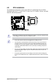
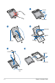
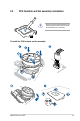
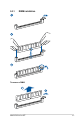
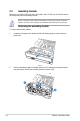
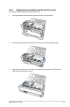
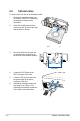
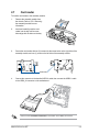
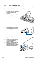
Table Of Contents
- Notices
- Chapter 1: Product Introduction
- Chapter 2: Hardware Setup
- 2.1 Chassis cover
- 2.2 CPU installation
- 2.3 CPU heatsink and fan assembly installation
- 2.4 System memory
- 2.5 Assembly module
- 2.6 5.25-inch drive
- 2.7 Card reader
- 2.8 Hard disk drives (HDD)
- 2.9 Expansion slots
- 2.10 System fan
- 2.11 BIOS update utility
- 2.12 Motherboard rear and audio connection
- 2.13 Starting up for the first time
- 2.14 Turning off the computer
- Chapter 3: Motherboard Information
- Chapter 4: BIOS Setup
- Chapter 5: RAID Configuration
- Appendix

2-11
ASUS ESC510 G4 SFF
2.7 Card reader
To install a card reader to the assembly module:
1. Remove the assembly module from
the chassis. Refer to 2.5.1 Removing
the assembly module for more
information.
2. Insert and carefully push the card
reader into the bay until its screw
holes align with the holes on the bay.
3. Secure the card reader with two (2) screws into the screw holes on the right side of the
assembly module, and one (1) screw on the left side of the assembly module.
4. ConnecttheconnectortothebundledUSB3.0cable,thenconnecttheUSB3.0cable
totheUSB3_34connectoronthemotherboard.
Refer to section 3.4 Internal connectorsforthelocationoftheUSB3_34connector.
Screw holes