
User Guide
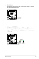
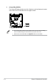
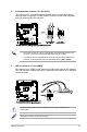
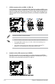
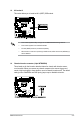
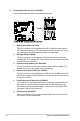
Table Of Contents
- Notices
- Chapter 1: Product Introduction
- Chapter 2: Hardware Setup
- 2.1 Chassis cover
- 2.2 CPU installation
- 2.3 CPU heatsink and fan assembly installation
- 2.4 System memory
- 2.5 Assembly module
- 2.6 5.25-inch drive
- 2.7 Card reader
- 2.8 Hard disk drives (HDD)
- 2.9 Expansion slots
- 2.10 System fan
- 2.11 BIOS update utility
- 2.12 Motherboard rear and audio connection
- 2.13 Starting up for the first time
- 2.14 Turning off the computer
- Chapter 3: Motherboard Information
- Chapter 4: BIOS Setup
- Chapter 5: RAID Configuration
- Appendix

ASUS ESC510 G4
3-11
3.4 Internal connectors
1. Serial port connector (10-1 pin COM1)
This connector is for the serial (COM) port. Connect the serial port module cable to one
of these connectors, then install the module to a slot opening at the back of the system
chassis.
2. Digital audio connector (4-1 pin SPDIF_OUT1)
This connector is for an additional Sony/Philips Digital Interface (S/PDIF) port. Connect
the S/PDIF Out module cable to this connector, then install the module to a slot
opening at the back of the system chassis.
The S/PDIF module is purchased separately.