
User Guide
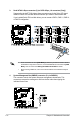
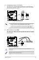
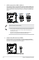
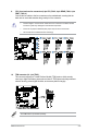
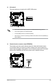
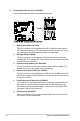
Table Of Contents
- Notices
- Chapter 1: Product Introduction
- Chapter 2: Hardware Setup
- 2.1 Chassis cover
- 2.2 CPU installation
- 2.3 CPU heatsink and fan assembly installation
- 2.4 System memory
- 2.5 Assembly module
- 2.6 5.25-inch drive
- 2.7 Card reader
- 2.8 Hard disk drives (HDD)
- 2.9 Expansion slots
- 2.10 System fan
- 2.11 BIOS update utility
- 2.12 Motherboard rear and audio connection
- 2.13 Starting up for the first time
- 2.14 Turning off the computer
- Chapter 3: Motherboard Information
- Chapter 4: BIOS Setup
- Chapter 5: RAID Configuration
- Appendix

ASUS ESC510 G4
3-17
13. M.2 socket 3
This socket allows you to install an M.2 (NGFF) SSD module.
• This socket supports M Key and type 22110/2280/2260/2242 storage devices.
• This socket supports PCIe and SATA modes.
• The M.2 (NGFF) device is purchased separately.
• When the M.2 connector is operating in SATA mode, SATA connector 8 (SATA6G_8)
will be disabled.
14. Chassis intrusion connector (2-pin INTRUSION)
These leads are for the intrusion detection feature for chassis with intrusion sensor
or microswitch. When you remove any chassis component, the sensor triggers and
sends a high level signal to these leads to record a chassis intrusion event. The default
setting is short CHASSIS# and GND pin by jumper cap to disable the function.