• F1A55-M LX3 R2.0 • F1A55-M LX3 PLUS R2.0 Motherboard F1A55-M LX3 R2.
E8003 Second Edition December 2012 Copyright © 2012 ASUSTeK COMPUTER INC. All Rights Reserved. No part of this manual, including the products and software described in it, may be reproduced, transmitted, transcribed, stored in a retrieval system, or translated into any language in any form or by any means, except documentation kept by the purchaser for backup purposes, without the express written permission of ASUSTeK COMPUTER INC. (“ASUS”).
Contents Safety information....................................................................................................... vi About this guide.......................................................................................................... vi F1A55-M LX3 R2.0 Series specifications summary............................................... viii Package contents......................................................................................................... x Chapter 1: 1.1 1.1.
2.1.2 ASUS EZ Flash 2............................................................................. 2-2 2.1.4 ASUS BIOS Updater........................................................................ 2-4 2.1.3 2.2 2.3 BIOS setup program...................................................................................... 2-6 Main menu.................................................................................................... 2-10 2.3.1 System Language [English].................................
2.7.5 Setup Mode [EZ Mode].................................................................. 2-24 2.7.7 PCI ROM Priority [Legacy ROM]................................................... 2-24 2.7.6 2.7.8 2.8 2.7.9 Boot Option Priorities..................................................................... 2-24 Boot Override................................................................................. 2-24 Tools menu......................................................................................
Safety information Electrical safety • • • • • • To prevent electrical shock hazard, disconnect the power cable from the electrical outlet before relocating the system. When adding or removing devices to or from the system, ensure that the power cables for the devices are unplugged before the signal cables are connected. If possible, disconnect all power cables from the existing system before you add a device.
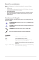
Where to find more information Refer to the following sources for additional information and for product and software updates. 1. 2. ASUS websites The ASUS website provides updated information on ASUS hardware and software products. Refer to the ASUS contact information. Optional documentation Your product package may include optional documentation, such as warranty flyers, that may have been added by your dealer. These documents are not part of the standard package.
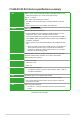
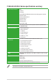
F1A55-M LX3 R2.0 Series specifications summary APU AMD® A- & E2- series accelerated processors with AMD® Radeon™ HD 6000 series graphics, up to 4 CPU cores, FM1 package DirectX® 11 support AMD® Turbo Core Technology 2.0 support* * The AMD® Turbo Core Technology 2.0 support depends on the APU types. ** Refer to www.asus.com for the AMD® CPU support list.
F1A55-M LX3 R2.0 Series specifications summary ASUS unique features EPU AI Suite II Anti-Surge ASUS UEFI BIOS EZ Mode featuring user-friendly graphics interface ASUS Fan Xpert ASUS CrashFree BIOS 3 ASUS EZ Flash 2 Network iControl ASUS MyLogo 2 Hybrid DIGI+ VRM Special features 100% All high quality conductive polymer capacitors (F1A55-M LX3 PLUS R2.0 only) Back Panel I/O ports 1 x PS/2 keyboard port 1 x PS/2 mouse port 1 x COM port 1 x D-Sub output port 1 x LAN (RJ-45) port 4 x USB 2.0/1.
Package contents Check your motherboard package for the following items. 18.5cm(7.3in) KBMS CPU_FAN ATX12V USBPW1-4 Super I/O AUDIO F1A55-M LX3 PLUS R2.0 PCIEX16 AR 8161 PCIEX1_1 22.6cm(8.
Product introduction 1.1 Special features 1.1.1 Product highlights 1 AMD A- & E2- series accelerated processors with AMD® Radeon™ HD 6000 series graphics ® This motherboard supports AMD® A- & E2- series accelerated processor with AMD® Radeon™ HD 6000 series graphics. This revolutionary APU (Accelerated Processing Unit) combines processing power and advanced DirectX 11 graphics in one small, energy-efficient design to enable accelerated performance and an industry-leading visual experience.
1.1.3 ASUS Exclusive Features Network iControl Network iControl is an intuitive one-step network control center that makes it easier for you to manage your bandwidth and allows you to set, monitor, and schedule the bandwidth priorities for your network programs. It allows you to automatically connect to a PPPoE network for a more convenient online experience. * The ASUS Network iControl feature does not support Windows® XP/Vista operating systems.
C.P.R. (CPU Parameter Recall) The BIOS C.P.R. feature automatically restores the CPU default settings when the system hangs due to overclocking failure. C.P.R. eliminates the need to open the system chassis and clear the RTC data. Simply shut down and reboot the system, and the BIOS automatically restores the CPU parameters to their default settings.
1.2 Before you proceed Take note of the following precautions before you install motherboard components or change any motherboard settings. • Unplug the power cord from the wall socket before touching any component. • Before handling components, use a grounded wrist strap or touch a safely grounded object or a metal object, such as the power supply case, to avoid damaging them due to static electricity. • Hold components by the edges to avoid touching the ICs on them.
1.3 Motherboard overview 1.3.1 Placement direction 1.3.2 Screw holes When installing the motherboard, ensure that you place it into the chassis in the correct orientation. The edge with external ports goes to the rear part of the chassis as indicated in the image below. Place six screws into the holes indicated by circles to secure the motherboard to the chassis. DO NOT overtighten the screws! Doing so can damage the motherboard. Place this side towards the rear of the chassis. F1A55-M LX3 PLUS R2.
1.3.3 Motherboard layout F1A55-M LX3 R2.0 Series motherboards include F1A55-M LX3 PLUS R2.0 and F1A55-M LX3 R2.0 models. The package contents vary from models. The layout illustrations in this user guide are for F1A55-M LX3 PLUS R2.0 only. 1 2 3 4 5 3 6 18.5cm(7.3in) KBMS CPU_FAN ATX12V CHA_FAN USBPW1-4 LAN_USB12 Super I/O AUDIO SATA3G_3 F1A55-M LX3 PLUS R2.
1.3.4 Layout contents Connectors/Jumpers/Slots/LED Page 2. USB device wake-up (3-pin USBPW1-4, 3-pin USBPW5-8) 1-20 4. ATX power connectors (24-pin EATXPWR, 4-pin ATX12V) 1-23 1. Keyboard power (3-pin KBPWR) 3. CPU and chassis fan connectors (4-pin CPU_FAN and 3-pin CHA_FAN) 5. AMD FM1 socket 6. DDR3 DIMM slots 7. SATA 3.0Gb/s connectors (7-pin SATA3G_1~4) 9. Speaker connector (4-pin SPEAKER) 8. System panel connector (10-1 pin F_PANEL) 10. Standby power LED (SB_PWR) 11. USB 2.
1.4.
1.4.2 APU heatsink and fan assembly installation Apply the Thermal Interface Material to the APU heatsink and APU before you install the heatsink and fan if necessary. To install the APU heatsink and fan assembly 1 2 3 4 ASUS F1A55-M LX3 R2.
To uninstall the APU heatsink and fan assembly 1 3 2 4 5 1-10 Chapter 1: Product introduction
1.5 System memory 1.5.1 Overview This motherboard comes with two Double Data Rate 3 (DDR3) Dual Inline Memory Modules (DIMM) sockets. A DDR3 module has the same physical dimensions as a DDR2 DIMM but is notched differently to prevent installation on a DDR2 DIMM socket. DDR3 modules are developed for better performance with less power consumption. DIMM_A1 DIMM_B1 The figure illustrates the location of the DDR3 DIMM sockets: Channel Channel A Channel B Sockets DIMM_A1 DIMM_B1 F1A55-M LX3 PLUS R2.
1.5.2 Memory configurations You may install 1GB, 2GB, 4GB, and 8GB unbuffered non-ECC DDR3 DIMMs into the DIMM sockets. • You may install varying memory sizes in Channel A and Channel B. The system maps the total size of the lower-sized channel for the dual-channel configuration. Any excess memory from the higher-sized channel is then mapped for single-channel operation. • Always install DIMMs with the same CAS latency.
DDR3-1333MHz capability DIMM socket support (Optional) A* B* Vendors Part No. Size SS/ DS Chip Brand Chip No. Timing Voltage A-Data AD31333001GOU 1GB SS A-Data AD30908C8D-151C E0906 - - • • A-Data AD63I1B0823EV 2GB SS A-Data 3CCA-1509A - - • • A-Data AXDU1333GC2G9-2G (XMP) AD63I1C1624EV 78.A1GC6.9L1 78.A1GC6.9L1 78.B1GDE.9L10C CM3X1024-1333C9 TR3X3G1333C9 G TR3X6G1333C9 G CMD24GX3M6A 1333C9(XMP) TW3X4G13 33C9D G CMD8GX3M 4A1333C7 CT12864BA 1339.8FF CT25664BA 1339.
DDR3-1333MHz capability Vendors Part No. Hynix Hynix Kingmax Kingmax KINGMAX Kingmax Kingmax KINGMAX Kingmax KINGSTON KINGSTON KINGSTON KINGSTON KINGSTON KINGSTON KINGSTON KINGSTON KINGSTON Micron Micron Micron Micron Micron PSC PSC SAMSUNG SAMSUNG SAMSUNG SAMSUNG Super Talent Super Talent Super Talent Super Talent Super Talent Transcend Transcend Transcend WINTEC 1-14 Size DIMM socket support (Optional) A* B* SS/DS Chip Brand Chip No.
DDR3-1600MHz capability Size SS/ Chip Chip No. DS Brand Timing AX3U1600XB2G79-2X(XMP) AX3U1600GC4G9-2G(XMP) AX3U1600XC4G79-2X(XMP) TR3X3G1600C8D(XMP) CMD12GX3M6A1600C8(XMP) CMP4GX3M2C1600C7(XMP) CMX4GX3M2A1600C9(XMP) TR3X6G1600C8 G(XMP) TR3X6G1600C8D G(XMP) CMP8GX3M2A1600C9(XMP) CMX8GX3M4A1600C9(XMP) BL25664BN1608.
DDR3-1866MHz capability Vendors Part No. Size SS/ Chip Chip Timing DS Brand No. DIMM socket support Voltage (Optional) A* B* CORSAIR CORSAIR CORSAIR G.SKILL KINGSTON CMT4GX3M2A1866C9(XMP) CMT6GX3MA1866C9(XMP) CMZ8GX3M2A1866C9(XMP) F3-14900CL9D-8GBXL(XMP) KHX1866C9D3T1K3/3GX(XMP) 4GB(2 x 2GB) 6GB(3 x 2GB) 8GB(2 x 4GB) 8GB(2 x 4GB) 3GB(3 x 1GB) DS DS DS DS SS 1.65V 1.65V 1.50V 1.5V 1.65V KINGSTON KHX1866C9D3T1K3/6GX(XMP) 6GB(3 x 2GB) DS - - 9-9-9-24 9-9-9-24 9-10-9-27 9-10-9-28 - 1.
1.5.3 Installing a DIMM 1 2 3 To remove a DIMM B A ASUS F1A55-M LX3 R2.
1.6 Expansion slots In the future, you may need to install expansion cards. The following sub‑sections describe the slots and the expansion cards that they support. Unplug the power cord before adding or removing expansion cards. Failure to do so may cause you physical injury and damage motherboard components. 1.6.1 Installing an expansion card To install an expansion card: 1.
1.7 1. Jumpers Clear RTC RAM (CLRTC) This jumper allows you to clear the Real Time Clock (RTC) RAM in CMOS. You can clear the CMOS memory of date, time, and system setup parameters by erasing the CMOS RTC RAM data. The onboard button cell battery powers the RAM data in CMOS, which include system setup information such as system passwords. To erase the RTC RAM: CLRTC F1A55-M LX3 PLUS R2.0 1 2 2 Normal (Default) Clear RTC 3 F1A55-M LX3 PLUS R2.0 Clear RTC RAM 1.
2. Keyboard power (3-pin KBPWR) This jumper allows you to enable or disable the keyboard wake-up feature. When you set this jumper to pins 2–3 (+5VSB), you can wake up the computer by pressing a key on the keyboard. This feature requires an ATX power supply that can supply at least 1A on the +5VSB lead, and a corresponding setting in the BIOS. 1 2 2 3 KBPWR F1A55-M LX3 PLUS R2.0 +5V (Default) +5VSB F1A55-M LX3 PLUS R2.0 Keyboard power setting 3.
1.8 Connectors 1.8.1 Rear panel ports 1 2 10 9 8 7 3 4 6 5 1. PS/2 Mouse port (green). This port is for a PS/2 mouse. 2. LAN (RJ-45) port. This port allows Gigabit connection to a Local Area Network (LAN) through a network hub. LAN port LED indications Activity/Link LED Status Description OFF No link ORANGE Linked BLINKING Data activity Speed LED Status Description OFF 10Mbps connection ORANGE 100Mbps connection GREEN 1Gbps connection ACT/LINK SPEED LED LED LAN port 3.
6. USB 2.0 ports 1 and 2. These two 4-pin Universal Serial Bus (USB) ports are for USB 2.0/1.1 devices. 7. USB 2.0 ports 3 and 4. These two 4-pin Universal Serial Bus (USB) ports are for USB USB 2.0/1.1 devices. 8. Video Graphics Adapter (VGA) port. This 15-pin port is for a VGA monitor or other VGA-compatible devices. 9. COM port. This port is for pointing devices or other serial devices. 10. PS/2 Keyboard port (purple). This port is for a PS/2 keyboard. 1.8.2 1.
2. Speaker connector (4-pin SPEAKER) This 4-pin connector is for the chassis-mounted system warning speaker. The speaker allows you to hear system beeps and warnings. +5V GND GND Speaker Out SPEAKER F1A55-M LX3 PLUS R2.0 PIN 1 F1A55-M LX3 PLUS R2.0 Speaker out connector 3. ATX power connectors (24-pin EATXPWR, 4-pin ATX12V) These connectors are for an ATX power supply. The plugs from the power supply are designed to fit these connectors in only one orientation.
4. Serial ATA 3.0 Gb/s connectors (7-pin SATA3G_1~4) These connectors are for the Serial ATA 3.0 Gb/s signal cables for Serial ATA hard disk drives and optical disc drives. If you installed Serial ATA hard disk drives, you can create a RAID 0, RAID 1, or RAID 10 configuration through the onboard controller. GND RSATA_TXP2 RSATA_TXN2 GND RSATA_RXN2 RSATA_RXP2 GND SATA3G_2 GND RSATA_RXP1 RSATA_RXN1 GND RSATA_TXN1 RSATA_TXP1 GND SATA3G_1 F1A55-M LX3 PLUS R2.
5. System panel connector (10-1 pin F_PANEL) This connector supports several chassis-mounted functions. PWRBTN PLED+ PLEDPWR GND PLED F_PANEL HD_LED+ HD_LEDGround Reset PIN 1 F1A55-M LX3 PLUS R2.0 +HDLED RESET F1A55-M LX3 PLUS R2.0 System panel connector • • • • System power LED (2-pin PLED) This 2-pin connector is for the system power LED. Connect the chassis power LED cable to this connector.
Front panel audio connector (10-1 pin AAFP) NC AGND NC NC SENSE2_RETUR This connector is for a chassis-mounted front panel audio I/O module that supports either High Definition Audio or AC`97 audio standard. Connect one end of the front panel audio I/O module cable to this connector. AGND NC SENSE1_RETUR 6. AAFP HD-audio-compliant pin definition PIN 1 MIC2 MICPWR Line out_R NC Line out_L F1A55-M LX3 PLUS R2.
USB 2.0 connectors (10-1 pin USB56, USB78) These connectors are for USB 2.0 ports. Connect the USB module cable to any of these connectors, then install the module to a slot opening at the back of the system chassis. These USB connectors comply with USB 2.0 specification that supports up to 480Mbps connection speed. PIN 1 PIN 1 USB+5V USB_P7USB_P7+ GND F1A55-M LX3 PLUS R2.0 USB+5V USB_P6USB_P6+ GND NC USB56 USB+5V USB_P8USB_P8+ GND NC USB78 USB+5V USB_P5USB_P5+ GND 7. F1A55-M LX3 PLUS R2.0 USB2.
1.9 Software support 1.9.1 Installing an operating system This motherboard supports Windows® XP / Vista / 7 Operating Systems (OS). Always install the latest OS version and corresponding updates to maximize the features of your hardware. 1.9.2 • Motherboard settings and hardware options vary. Refer to your OS documentation for detailed information.
BIOS information 2.1 Managing and updating your BIOS 2 Save a copy of the original motherboard BIOS file to a USB flash disk in case you need to restore the BIOS in the future. Copy the original motherboard BIOS using the ASUS Update utility. 2.1.1 ASUS Update utility The ASUS Update is a utility that allows you to manage, save, and update the motherboard BIOS in Windows® environment. • ASUS Update requires an Internet connection either through a network or an Internet Service Provider (ISP).
Updating from the Internet a. Select Update BIOS from the Internet, then click Next. b. Select the ASUS FTP site nearest you to avoid network traffic, then click Next. c. From the FTP site, select the BIOS version that you wish to download then click Next. The ASUS Update utility is capable of updating itself through the Internet. Always update the utility to avail all its features. Updating from a BIOS file 3. a. Select Update BIOS from file, then click Next. b.
2.1.3 ASUS CrashFree BIOS 3 utility The ASUS CrashFree BIOS 3 is an auto recovery tool that allows you to restore the BIOS file when it fails or gets corrupted during the updating process. You can restore a corrupted BIOS file using the motherboard support DVD or a USB flash drive that contains the updated BIOS file. • Before using this utility, rename the BIOS file in the removable device into F1A5MLX3. CAP (for F1A55-M LX3 R2.0) or F1A5LX3P.CAP (for F1A55-M LX3 PLUS R2.0).
2.1.4 ASUS BIOS Updater The ASUS BIOS Updater allows you to update BIOS in DOS environment. This utility also allows you to copy the current BIOS file that you can use as a backup when the BIOS fails or gets corrupted during the updating process. The succeeding utility screens are for reference only. The actual utility screen displays may not be same as shown. Before updating BIOS 1. Prepare the motherboard support DVD and a USB flash drive in FAT32/16 format and single partition. 2.
Updating the BIOS file To update the BIOS file using BIOS Updater 1. At the FreeDOS prompt, type bupdater /pc /g and press . D:\>bupdater /pc /g 2. The BIOS Updater screen appears as below. ASUSTek BIOS Updater for DOS V1.30 Current ROM BOARD:F1A55-M LX3 PLUS R2.0 VER: 0401 DATE: 05/02/2012 Update ROM BOARD: Unknown VER: Unknown DATE: Unknown PATH: A:\ F1A5MLX3.CAP A: Note [Enter] Select or Load [Up/Down/Home/End] Move 3.
2.2 BIOS setup program Use the BIOS Setup program to update the BIOS or configure its parameters. The BIOS screens include navigation keys and brief online help to guide you in using the BIOS Setup program. Entering BIOS Setup at startup To enter BIOS Setup at startup: • Press during the Power-On Self Test (POST). If you do not press , POST continues with its routines. Entering BIOS Setup after POST To enter BIOS Setup after POST: • Press ++ simultaneously.
BIOS menu screen The BIOS setup program can be used under two modes: EZ Mode and Advanced Mode. You can change modes from the Exit menu or from the Exit/Advanced Mode button in the EZ Mode/Advanced Mode screen. EZ Mode By default, the EZ Mode screen appears when you enter the BIOS setup program. The EZ Mode provides you an overview of the basic system information, and allows you to select the display language, system performance mode and boot device priority.
Advanced Mode The Advanced Mode provides advanced options for experienced end-users to configure the BIOS settings. The figure below shows an example of the Advanced Mode. Refer to the following sections for the detailed configurations. To access the EZ Mode, click Exit, then select ASUS EZ Mode.
Menu items The highlighted item on the menu bar displays the specific items for that menu. For example, selecting Main shows the Main menu items. The other items (Ai Tweaker, Advanced, Monitor, Boot, Tool, and Exit) on the menu bar have their respective menu items. Back button This button appears when entering a submenu. Press or use the USB mouse to click this button to return to the previous menu screen.
2.3 Main menu The Main menu screen appears when you enter the Advanced Mode of the BIOS Setup program. The Main menu provides you an overview of the basic system information, and allows you to set the system date, time, language, and security settings.
Administrator Password If you have set an administrator password, we recommend that you enter the administrator password for accessing the system. Otherwise, you might be able to see or change only selected fields in the BIOS setup program. To set an administrator password: 1. Select the Administrator Password item and press . 2. From the Create New Password box, key in a password, then press . 3. Confirm the password when prompted. To change an administrator password: 1.
2.4 Ai Tweaker menu The Ai Tweaker menu items allow you to configure overclocking-related items. Be cautious when changing the settings of the Ai Tweaker menu items. Incorrect field values can cause the system to malfunction. The configuration options for this section vary depending on the CPU and DIMM model you installed on the motherboard. Scroll down to display the following items: Target CPU Speed : xxxxMHz Displays the current CPU speed. Target DRAM Speed : xxxxMHz Displays the current DRAM speed.
2.4.1 Ai Overclock Tuner [Auto] Allows you to select the CPU overclocking options to achieve the desired CPU internal frequency. Select any of these preset overclocking configuration options: [Auto] Loads the optimal settings for the system. [Manual] Allows you to individually set overclocking parameters. [D.O.C.P.] Allows you to select a DRAM O.C. profile, and the related parameters will be adjusted automatically.
2.4.5 DRAM Timing Control The sub-items in this menu allow you to set the DRAM timing control features. Use the <+> and <-> keys to adjust the value. To restore the default setting, type [auto] using the keyboard and press . Changing the values in this menu may cause the system to become unstable! If this happens, revert to the default settings. 2.4.6 Hybrid ��������� DIGI+ VRM Load-Line Calibration [Auto] Load-line is defined by AMD VRM specifications, and affects CPU voltage.
2.4.7 CPU Voltage [Offset Mode] [Offset Mode] To offset the voltage by a positive or negative value. CPU Offset Mode Sign [+] [+] [–] To offset the voltage by a positive value. To offset the voltage by a negative value. CPU Offset Voltage [Auto] Allows you to set the CPU Offset voltage. The values range from 0.000V to 0.500V with a 0.00625V interval. Refer to the CPU documentation before setting the CPU voltage.
2.5 Advanced menu The Advanced menu items allow you to change the settings for the CPU and other system devices. Be cautious when changing the settings of the Advanced menu items. Incorrect field values can cause the system to malfunction.
AMD PowerNow function [Enabled] Enables or disables the AMD PowerNow function. Configuration options: [Enabled] [Disabled] SVM [Enabled] Enables or disables CPU virtualization. Configuration options: [Disabled] [Enabled] C-state Pmin [Enabled] When this item is set to [Enabled], the system’s processor operates at the lowest power and operating state (C-state). Configuration options: [Disabled] [Enabled] 2.5.
2.5.3 USB Configuration The items in this menu allow you to change the USB-related features. The USB Devices item shows the auto-detected values. If no USB device is detected, the item shows None. Legacy USB Support [Enabled] [Enabled] [Disabled] [Auto] Enables the support for USB devices on legacy operating systems (OS). The USB devices can be used only for the BIOS setup program. Allows the system to detect the presence of USB devices at startup. If detected, the USB controller legacy mode is enabled.
Atheros Lan [Enabled] [Enabled] [Disabled] Enables the Atheros LAN controller. Disables the Atheros LAN controller. Atheros Rom [Disabled] This item appears only when you set the previous item to [Enabled] and allows you to enable or disable the Rom Help of the Atheros LAN controller. Configuration options: [Enabled] [Disabled] Serial Port Configuration The sub-items in this menu allow you to set the serial port configuration.
Power On By RTC [Disabled] [Disabled] [Enabled] 2.5.7 Disables RTC to generate a wake event. When set to [Enabled], the items RTC Alarm Date (Days) and Hour/ Minute/Second will become user-configurable with set values. Network Stack Network Stack [Disable Link] This item allows user to disable or enable the UEFI network stack. Configuration options: [Disable Link] [Enabled] The following two items appear only when you set the previous item to [Enabled].
2.6 Monitor menu The Monitor menu displays the system temperature/power status, and allows you to change the fan settings. EFI BIOS Utility - Advanced Mode Main Ai Tweaker Exit Advanced Monitor CPU Temperature �������������� +45ºC / +113ºF MB Temperature CPU Fan Speed Boot Tool CPU Temperature +34ºC / +93ºF 4515 RPM Chassis Fan Speed N/A CPU Q-Fan Control Enabled CPU Fan Speed Low Limit 600 RPM CPU Fan Profile Standard CPU Voltage +1.384 V 3.3V Voltage +3.
CPU Fan Profile [Standard] This item appears only when you enable the CPU Q-Fan Control feature and allows you to set the appropriate performance level of the CPU fan. [Standard] Sets to [Standard] to make the CPU fan automatically adjust depending on the CPU temperature. [Silent] Sets to [Silent] to minimize the fan speed for quiet CPU fan operation. [Turbo] Sets to [Turbo] to achieve maximum CPU fan speed. [Manual] Sets to [Manual] to assign detailed fan speed control parameters.
2.7 Boot menu The Boot menu items allow you to change the system boot options. 2.7.1 Bootup NumLock State [On] 2.7.2 Full Screen Logo [Enabled] [On] [Off] [Enabled] [Disabled] Sets the power-on state of the NumLock to [On]. Sets the power-on state of the NumLock to [Off]. Enables the full screen logo display feature. Disables the full screen logo display feature. Set this item to [Enabled] to use the ASUS MyLogo 2™ feature.
2.7.4 [Force BIOS] Option ROM Messages [Force BIOS] [Keep Current] The third-party ROM messages will be forced to display during the boot sequence. The third-party ROM messages will be displayed only if the third-party manufacturer had set the add-on device to do so. 2.7.5 Setup Mode [EZ Mode] 2.7.6 UEFI/Legacy Boot [Enabled both UEFI and Legacy] 2.7.7 PCI ROM Priority [Legacy ROM] 2.7.
2.8 Tools menu The Tools menu items allow you to configure options for special functions. Select an item then press to display the submenu. EFI BIOS Utility - Advanced Mode Ai Tweaker Main Advanced Exit Monitor Boot Tool Be used to update BIOS > ASUS EZ Flash 2 Utility > ASUS O.C. Profile > ASUS SPD Information 2.8.1 ASUS EZ Flash 2 Utility Allows you to run ASUS EZ Flash 2. Press [Enter] to launch the ASUS EZ Flash 2 screen. For more details, see section 2.1.2 ASUS EZ Flash 2. 2.8.
2.9 Exit menu The Exit menu items allow you to load the optimal default values for the BIOS items, and save or discard your changes to the BIOS items. You can access the EZ Mode from the Exit menu. Exit Load Optimized Defaults Save Changes & Reset Discard Changes & Exit ASUS EZ Mode Launch EFI Shell from filesystem device Load Optimized Defaults This option allows you to load the default values for each of the parameters on the Setup menus.
Appendices Notices Federal Communications Commission Statement This device complies with Part 15 of the FCC Rules. Operation is subject to the following two conditions: • • This device may not cause harmful interference. This device must accept any interference received including interference that may cause undesired operation. This equipment has been tested and found to comply with the limits for a Class B digital device, pursuant to Part 15 of the FCC Rules.
Canadian Department of Communications Statement This digital apparatus does not exceed the Class B limits for radio noise emissions from digital apparatus set out in the Radio Interference Regulations of the Canadian Department of Communications. This class B digital apparatus complies with Canadian ICES-003.
ASUS contact information ASUSTeK COMPUTER INC. Address Telephone Fax E-mail Web site Technical Support Telephone Online support 15 Li-Te Road, Peitou, Taipei, Taiwan 11259 +886-2-2894-3447 +886-2-2890-7798 info@asus.com.tw www.asus.com.tw +86-21-38429911 support.asus.
A-4 Appendices (510)739-3777/(510)608-4555 800 Corporate Way, Fremont, CA 94539. Asus Computer International Signature : Date : Representative Person’s Name : Mar. 28, 2012 Steve Chang / President This device complies with part 15 of the FCC Rules. Operation is subject to the following two conditions: (1) This device may not cause harmful interference, and (2) this device must accept any interference received, including interference that may cause undesired operation.
F1A55-M LX3 R2.0 Series A-5 (510)739-3777/(510)608-4555 800 Corporate Way, Fremont, CA 94539. Asus Computer International Signature : Date : Representative Person’s Name : Jun. 20, 2012 Steve Chang / President This device complies with part 15 of the FCC Rules. Operation is subject to the following two conditions: (1) This device may not cause harmful interference, and (2) this device must accept any interference received, including interference that may cause undesired operation.