Motherboard F1A75-M PRO
E6728 Second Edition (V2) June 2011 Copyright © 2011 ASUSTeK Computer Inc. All Rights Reserved. No part of this manual, including the products and software described in it, may be reproduced, transmitted, transcribed, stored in a retrieval system, or translated into any language in any form or by any means, except documentation kept by the purchaser for backup purposes, without the express written permission of ASUSTeK Computer Inc. (“ASUS”).
Contents Notices.......................................................................................................... vi Safety information...................................................................................... vii About this guide........................................................................................ viii F1A75-M PRO specifications summary..................................................... ix Chapter 1: Product introduction 1.1 Welcome!..............................
Contents 1.11 Onboard switch........................................................................... 1-25 1.13 Software support......................................................................... 1-29 1.12 Onboard LEDs............................................................................. 1-27 1.13.1 1.13.2 Installing an operating system....................................... 1-29 Support DVD information............................................... 1-29 Chapter 2: BIOS information 2.
Contents 2.5.3 USB Configuration......................................................... 2-19 2.5.5 Onboard Devices Configuration..................................... 2-20 2.5.4 2.6 2.5.6 NB Configuration............................................................ 2-20 APM............................................................................... 2-21 Monitor menu.............................................................................. 2-22 2.6.
Notices Federal Communications Commission Statement This device complies with Part 15 of the FCC Rules. Operation is subject to the following two conditions: • This device may not cause harmful interference, and • This device must accept any interference received including interference that may cause undesired operation. This equipment has been tested and found to comply with the limits for a Class B digital device, pursuant to Part 15 of the FCC Rules.
REACH Complying with the REACH (Registration, Evaluation, Authorisation, and Restriction of Chemicals) regulatory framework, we published the chemical substances in our products at ASUS REACH website at http://csr.asus.com/english/REACH.htm. DO NOT throw the motherboard in municipal waste. This product has been designed to enable proper reuse of parts and recycling.
About this guide This user guide contains the information you need when installing and configuring the motherboard. How this guide is organized This guide contains the following parts: • Chapter 1: Product introduction • This chapter describes the features of the motherboard and the new technology it supports. Chapter 2: BIOS information This chapter tells how to change system settings through the BIOS Setup menus. Detailed descriptions of the BIOS parameters are also provided.
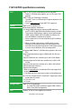
F1A75-M PRO specifications summary APU AMD® A- & E2- series accelerated processors with AMD® Radeon™ HD 6000 series graphics, up to 4 CPU cores, FM1 package AMD® Turbo Core Technology 2.0 support * The AMD® Turbo Core Technology 2.0 support depends on the APU types. ** Refer to www.asus.
F1A75-M PRO specifications summary Audio ALC892 8-channel High Definition Audio CODEC - Supports Jack-Detection, Multi-Streaming, and Front Panel Jack-Retasking - Supports S/PDIF out interface at the back I/O USB AMD® A75 FCH southbridge: - 10 x USB 2.0/1.1 ports (8 ports at the mid-board, 2 ports at the back panel) - 4 x USB 3.0 ports (2 ports at the mid-board, 2 ports at the back panel) Asmedia® PCIe USB3.0 controller: - 2 x USB 3.0/2.
F1A75-M PRO specifications summary ASUS exclusive overclocking features Intelligent overclocking tools: - TPU Switch - Auto Tuning Precision Tweaker 2 - vCore: Adjustable CPU voltage at 0.00625V increment - vDRAM Bus: 65-step memory voltage control - vFCH: 41-step chipset voltage control SFS (Stepless Frequency Selection): - PCIe frequency tuning from 100MHz up to 200MHz at 1MHz increment Overclocking Protection: - ASUS C.P.
xii
Chapter 1 Product introduction 1.1 Welcome! Thank you for buying an ASUS® F1A75-M PRO motherboard! The motherboard delivers a host of new features and latest technologies, making it another standout in the long line of ASUS quality motherboards! Before you start installing the motherboard, and hardware devices on it, check the items in your package with the list below. 1.2 Package contents Check your motherboard package for the following items.
AMD® A75 FCH (Hudson D3) Chipset AMD® A75 FCH (Hudson D3) is designed to support up to 5GT/s interface speed and PCI Express™ 2.0 x 16 (at x4 speed) graphics. It supports 6 x SATA 6Gb/s ports and 4 x USB 3.0 Ports. ATI® CrossFireX™ Technology ATI’s CrossFireX™ boosts image quality along with rendering speed, eliminating the need to scale down screen resolution to get high quality images. CrossFireX™ allows higher antialiasing, anisotropic filtering, shading, and texture settings.
EPU Tap into the world’s first real time PC power saving engine through a simple onboard switch or AI Suite II utility. Get total system-wide energy optimization by automatically detecting current PC loadings and intelligently moderating power consumption. This also reduces fan noise and extends component longevity. 1.3.
ASUS UEFI BIOS (EZ Mode) The new ASUS UEFI BIOS is an Unified Extensible Firmware Interface that offers a user-friendly interface that goes beyond traditional keyboardonly BIOS controls to enable more flexible and convenient mouse input. Users can easily navigate the new UEFI BIOS with the same smoothness as their operating system. It natively supports hard drives larger than 2.2TB in 64-bit, with full storage space utilization, helping deliver far more exciting computing than traditional BIOS versions.
Fan Xpert ASUS Fan Xpert intelligently allows you to adjust the CPU fan speed according to different ambient temperatures caused by different climate conditions in different geographic regions and your PC’s loading. The built-in variety of useful profiles offer flexible controls of fan speed to achieve a quiet and cool environment. ASUS Q-Design ASUS Q-Design enhances your DIY experience.
1.4 Before you proceed Take note of the following precautions before you install motherboard components or change any motherboard settings. • Unplug the power cord from the wall socket before touching any component. • Before handling components, use a grounded wrist strap or touch a safely grounded object or a metal object, such as the power supply case, to avoid damaging them due to static electricity. • Hold components by the edges to avoid touching the ICs on them.
1.5 Motherboard overview 1.5.1 Placement direction 1.5.2 Screw holes When installing the motherboard, ensure that you place it into the chassis in the correct orientation. The edge with external ports goes to the rear part of the chassis as indicated in the image below. Place eight screws into the holes indicated by circles to secure the motherboard to the chassis. DO NOT overtighten the screws! Doing so can damage the motherboard. Place this side towards the rear of the chassis.
1.5.3 Motherboard layout 1 2 1 3 4 24.4cm(9.6in) KB_USB3_34 CPU_FAN EATX12V EPU TPU 2 24.4cm(9.6in) DDR3 DIMM_B2 (64bit, 240-pin module) 10 DRAM_LED CHA_FAN2 F1A75-M PRO 1 SB_PWR AMD® A75 PCI1 PCIEX16_2 SPDIF_OUT COM1 USB78 32Mb BIOS USB910 USB34 USB56 USB3_56 CLRTC AAFP SATA6G_1 SATA6G_3 SATA6G_5 SATA6G_2 SATA6G_4 SATA6G_6 TPU Super I/O PANEL 19 18 17 16 15 11 12 13 14 Layout contents Connectors/Jumpers/Slots/LED Page Connectors/Jumpers/Slots/LED Page 1.
1.6 Accelerated Processing Unit (APU) This motherboard comes with an FM1 socket designed for AMD® A- & E2- series accelerated processors with AMD® Radeon™ HD 6000 series graphics. Ensure that you use a APU designed for the FM1 socket. The APU fits in only one correct orientation. DO NOT force the APU into the socket to prevent bending the pins and damaging the APU! 1.6.1 Installing the APU To install a APU: 1. Locate the FM1 socket on the motherboard. F1A75-M PRO F1A75-M PRO processor socket FM1 2.
5. When the APU is in place, push down the socket lever to secure the APU. The lever clicks on the side tab to indicate that it is locked. 6. Install a APU heatsink and fan following the instructions that comes with the heatsink package. You can also refer to section 1.6.2 Installing heatsink and fan for instructions. 7. Connect the CPU fan cable to the CPU_FAN connector on the motherboard.
1.6.2 Installing the heatsink and fan Ensure that you use only AMD-certified heatsink and fan assembly. To install the CPU heatsink and fan: 1. Place the heatsink on top of the installed CPU, ensuring that the heatsink fits properly on the retention module base. • The retention module base is already installed on the motherboard upon purchase. • You do not have to remove the retention module base when installing the CPU or installing other motherboard components.
3. Align the other end of the retention bracket to the retention module base. A clicking sound denotes that the retention bracket is in place. Ensure that the fan and heatsink assembly perfectly fits the retention mechanism module base, otherwise you cannot snap the retention bracket in place. 4. Push down the retention bracket lock on the retention mechanism to secure the heatsink and fan to the module base. 5.
1.7.2 Memory configurations You may install 512MB, 1GB, 2GB, and 4GB unbuffered non-ECC DDR3 DIMMs into the DIMM sockets. • You may install varying memory sizes in Channel A and Channel B. The system maps the total size of the lower-sized channel for the dual-channel configuration. Any excess memory from the higher-sized channel is then mapped for single-channel operation. • We recommend that you install the memory modules from the blue slots for better overclocking capability.
1.7.3 Installing a DIMM Unplug the power supply before adding or removing DIMMs or other system components. Failure to do so can cause severe damage to both the motherboard and the components. 2 1. Press the retaining clips outward to unlock a DIMM socket. 2. Align a DIMM on the socket such that the notch on the DIMM matches the DIMM slot key on the socket. DIMM notch 1 1 DIMM slot key Unlocked retaining clip A DIMM is keyed with a notch so that it fits in only one direction.
1.8 Expansion slots In the future, you may need to install expansion cards. The following sub‑sections describe the slots and the expansion cards that they support. Unplug the power cord before adding or removing expansion cards. Failure to do so may cause you physical injury and damage motherboard components. 1.8.1 Installing an expansion card To install an expansion card: 1.
VGA configuration PCI Express operating mode PCIe x16_1 PCIe x16_2 Single VGA/PCIe card x16 (Recommended for single VGA card) N/A Dual VGA/PCIe card x16 x4 • In single VGA card mode, use the PCIe 2.0 x16_1 slot (blue) for a PCI Express x16 graphics card to get better performance. • We recommend that you provide sufficient power when running CrossFireX™ mode. See page 1-20 for details.
1.10 Connectors 1.10.1 Rear panel ports 1 2 3 15 14 13 4 12 11 5 6 7 8 10 9 1. PS/2 Keyboard/Mouse Combo port (purple/green). This port is for a PS/2 keyboard or PS/2 mouse. 2. Optical S/PDIF Out port. This port connects an external audio output device via an optical S/PDIF cable. 3. Video Graphics Adapter (VGA) port. This 15-pin port is for a VGA monitor or other VGA-compatible devices. 4. LAN (RJ-45) port.
Refer to the audio configuration table below for the function of the audio ports in the 2, 4, 6, or 8-channel configuration.
1.10.2 1. Internal connectors Power, CPU and chassis fan connectors (3-pin PWR FAN, 4-pin CPU_FAN, and 4-pin CHA_FAN1/2) Connect the fan cables to the fan connectors on the motherboard, ensuring that the black wire of each cable matches the ground pin of the connector.
2. ATX power connectors (24-pin EATXPWR, 8-pin EATX12V) These connectors are for an ATX power supply. The plugs from the power supply are designed to fit these connectors in only one orientation. Find the proper orientation and push down firmly until the connectors completely fit.
Serial ATA 6.0 Gb/s connectors (7-pin SATA6G 1~6) These connectors are for the Serial ATA 6.0 Gb/s signal cables for Serial ATA hard disk drives and optical disc drives. If you installed Serial ATA hard disk drives, you can create a RAID 0, RAID 1, or RAID 10 configuration through the onboard controller.
5. System panel connector (20-8 pin PANEL) This connector supports several chassis-mounted functions.
Digital audio connector (4-1 pin SPDIF_OUT) SPDIFOUT GND This connector is for an additional Sony/Philips Digital Interface (S/PDIF) port. +5V 6. F1A75-M PRO SPDIF_OUT F1A75-M PRO Digital audio connector Ensure that the audio device of Sound playback is Realtek High Definition Audio (the name may be different based on the OS). Go to Start > Control Panel > Sounds and Audio Devices > Sound Playback to configure the setting. The S/PDIF module is purchased separately.
USB 2.0 connectors (10-1 pin USB34, USB56, USB78, USB910) These connectors are for USB 2.0 ports. Connect the USB module cable to any of these connectors, then install the module to a slot opening at the back of the system chassis. These USB connectors comply with USB 2.0 specification that supports up to 480Mbps connection speed. USB34 USB+5V USB_P8USB_P8+ GND NC USB56 USB+5V USB_P6USB_P6+ GND NC USB910 USB+5V USB_P10USB_P10+ GND NC USB78 USB+5V USB_P4USB_P4+ GND NC 8.
1.11 Onboard switch Onboard switches allow you to fine-tune performance when working on a bare or open-case system. This is ideal for overclockers and gamers who continually change settings to enhance system performance. 1. MemOK! switch Installing DIMMs that are incompatible with the motherboard may cause system boot failure, and the DRAM_LED near the MemOK! switch lights continuously.
2. TPU switch This switch allows you to enable or disable the TPU function. TPU F1A75-M PRO F1A75-M PRO TPU switch 3. EPU switch This switch allows you to enable or disable the EPU function.
1.12 1. Onboard LEDs Standby Power LED The motherboard comes with a standby power LED that lights up to indicate that the system is ON, in sleep mode, or in soft-off mode. This is a reminder that you should shut down the system and unplug the power cable before removing or plugging in any motherboard component. The illustration below shows the location of the onboard LED. SB_PWR F1A75-M PRO ON Standby Power OFF Powered Off F1A75-M PRO Onboard LED 2.
3. TPU LED The TPU LED lights when the TPU switch is turned to Enable. ELED730 F1A75-M PRO F1A75-M PRO TPU LED 4. EPU LED The EPU LED lights when the EPU switch is turned to Enable.
1.13 Software support 1.13.1 Installing an operating system This motherboard supports Windows® XP / Vista / 7 Operating Systems (OS). Always install the latest OS version and corresponding updates to maximize the features of your hardware. • Motherboard settings and hardware options vary. Refer to your OS documentation for detailed information.
1-30 Chapter 1: Product introduction
Chapter 2 BIOS information 2.1 Managing and updating your BIOS Save a copy of the original motherboard BIOS file to a USB flash disk in case you need to restore the BIOS in the future. Copy the original motherboard BIOS using the ASUS Update utility. 2.1.1 ASUS Update utility The ASUS Update is a utility that allows you to manage, save, and update the motherboard BIOS in Windows® environment. • ASUS Update requires an Internet connection either through a network or an Internet Service Provider (ISP).
The ASUS Update utility is capable of updating itself through the Internet. Always update the utility to avail all its features. Updating from a BIOS file Select Update BIOS from file, then click Next. a. 3. Locate the BIOS file from the Open window, then click Open. b. Follow the onscreen instructions to complete the updating process. 2.1.2 ASUS EZ Flash 2 The ASUS EZ Flash 2 feature allows you to update the BIOS without using an OS‑based utility.
3. 4. 5. 6. Press to switch to the Drive field. Press the Up/Down arrow keys to find the USB flash disk that contains the latest BIOS, and then press . Press to switch to the Folder Info field. Press the Up/Down arrow keys to find the BIOS file, and then press to perform the BIOS update process. Reboot the system when the update process is done. • This function supports USB flash disks with FAT 32/16 format and single partition only.
2.1.4 ASUS BIOS Updater The ASUS BIOS Updater allows you to update BIOS in DOS environment. This utility also allows you to copy the current BIOS file that you can use as a backup when the BIOS fails or gets corrupted during the updating process. The succeeding utility screens are for reference only. The actual utility screen displays may not be same as shown. Before updating BIOS 1. 2. Prepare the motherboard support DVD and a USB flash drive in FAT32/16 format and single partition.
Backing up the current BIOS To backup the current BIOS file using the BIOS Updater Ensure that the USB flash drive is not write-protected and has enough free space to save the file. 1. At the FreeDOS prompt, type bupdater /o[filename] and press . D:\>bupdater /oOLDBIOS1.rom Filename Extension The [filename] is any user-assigned filename with no more than eight alphanumeric characters for the filename and three alphanumeric characters for the extension. 2.
Updating the BIOS file To update the BIOS file using BIOS Updater 1. At the FreeDOS prompt, type bupdater /pc /g and press . D:\>bupdater /pc /g 2. The BIOS Updater screen appears as below. ASUSTek BIOS Updater for DOS V1.07 Current ROM BOARD: F1A75-M PRO VER: 0301 DATE: 05/16/2011 Update ROM BOARD: Unknown VER: Unknown DATE: Unknown PATH: A:\ F1A75MP.ROM A: Note [Enter] Select or Load [Up/Down/Home/End] Move 3.
2.2 BIOS setup program Use the BIOS Setup program to update the BIOS or configure its parameters. The BIOS screens include navigation keys and brief online help to guide you in using the BIOS Setup program. Entering BIOS Setup at startup To enter BIOS Setup at startup: • Press during the Power-On Self Test (POST). If you do not press , POST continues with its routines. Entering BIOS Setup after POST To enter BIOS Setup after POST: • Press ++ simultaneously.
BIOS menu screen The BIOS setup program can be used under two modes: EZ Mode and Advanced Mode. You can change modes from the Exit menu or from the Exit/Advanced Mode button in the EZ Mode/Advanced Mode screen. EZ Mode By default, the EZ Mode screen appears when you enter the BIOS setup program. The EZ Mode provides you an overview of the basic system information, and allows you to select the display language, system performance mode and boot device priority.
Advanced Mode The Advanced Mode provides advanced options for experienced end-users to configure the BIOS settings. The figure below shows an example of the Advanced Mode. Refer to the following sections for the detailed configurations. To access the EZ Mode, click Exit, then select ASUS EZ Mode.
Menu items The highlighted item on the menu bar displays the specific items for that menu. For example, selecting Main shows the Main menu items. The other items (Ai Tweaker, Advanced, Monitor, Boot, Tool, and Exit) on the menu bar have their respective menu items. Back button This button appears when entering a submenu. Press or use the USB mouse to click this button to return to the previous menu screen.
2.3 Main menu The Main menu screen appears when you enter the Advanced Mode of the BIOS Setup program. The Main menu provides you an overview of the basic system information, and allows you to set the system date, time, language, and security settings.
Administrator Password If you have set an administrator password, we recommend that you enter the administrator password for accessing the system. Otherwise, you might be able to see or change only selected fields in the BIOS setup program. To set an administrator password: 1. Select the Administrator Password item and press . 3. Confirm the password when prompted. 2. From the Create New Password box, key in a password, then press . To change an administrator password: 1. 2. 3. 4.
2.4 Ai Tweaker menu The Ai Tweaker menu items allow you to configure overclocking-related items. Be cautious when changing the settings of the Ai Tweaker menu items. Incorrect field values can cause the system to malfunction. The configuration options for this section vary depending on the CPU and DIMM model you installed on the motherboard. EFI BIOS Utility - Advanced Mode Main Ai Tweaker Exit Advanced Monitor Target CPU Speed: XXXXMHz Boot Tool [X.M.P.
Target CPU Speed : xxxxMHz Displays the current CPU speed. Target DRAM Speed : xxxxMHz Displays the current DRAM speed. 2.4.1 Ai Overclock Tuner [Auto] Allows you to select the CPU overclocking options to achieve the desired CPU internal frequency. Select any of these preset overclocking configuration options: [Auto] Loads the optimal settings for the system. [Manual] Allows you to individually set overclocking parameters. [D.O.C.P.] Allows you to select a DRAM O.C.
2.4.5 OC Tuner 2.4.6 DRAM Timing Control OC Tuner automatically overclocks the frequency and voltage of CPU and DRAM for enhancing the system performance. Press and select OK to start automatic overclocking. The sub-items in this menu allow you to set the DRAM timing control features. Use the <+> and <-> keys to adjust the value. To restore the default setting, type [auto] using the keyboard and press .
2.4.8 DRAM Voltage [Auto] 2.4.9 SB 1.1V Voltage [Auto] 2.4.10 1.1Vsb Voltage [Auto] 2.4.11 APU1.2V Voltage [Auto] 2.4.12 VDDA Voltage [Auto] Allows you to set the DRAM voltage. The values range from 1.35V to 2.30V with a 0.01V interval. Allows you to set the Southbridge 1.1V voltage. The values range from 1.1V to 1.4V with a 0.01V interval. Allows you to set the 1.1Vsb voltage. The values range from 1.1000V to 1.2000V with a 0.1V interval. Allows you to set the APU (Accelerated Processor Unit) 1.
CPU/NB Current Capability [100%] This item provides wider total power range for overclocking. A higher value brings a wider total power range and extends the overclocking frequency range simultaneously. Configuration options: [100%] [110%] [120%] [130%] CPU Power Phase Control [Standard] Phase number is the number of working VRM phase. Increasing phase number under heavy system loading to get more transient and better thermal performance.
2.5 Advanced menu The Advanced menu items allow you to change the settings for the CPU and other system devices. Be cautious when changing the settings of the Advanced menu items. Incorrect field values can cause the system to malfunction. EFI BIOS Utility - Advanced Mode Ai Tweaker Main Advanced > CPU Configuration Exit Monitor Boot Tool CPU Configuration Parameters > SATA Configuration > USB Configuration > NB Configuration > Onboard Devices Configuration > APM 2.5.
2.5.2 SATA Configuration While entering Setup, the BIOS automatically detects the presence of SATA devices. The SATA Port items show Not Present if no SATA device is installed to the corresponding SATA port. OnChip SATA Channel [Enabled] Enables or disables onboard channel SATA port. Configuration options: [Disabled] [Enabled] OnChip SATA Type [IDE] Allows you to set the SATA configuration.
Legacy USB3.0 Support [Enabled] [Enabled] [Disabled] Enables the support for USB 3.0 devices on legacy operating systems (OS). Disables the function. EHCI Hand-off [Disabled] [Enabled] [Disabled] 2.5.4 Enables the support for operating systems without an EHCI hand‑off feature. Disables the function. NB Configuration IGFX Multi-Monitor [Disabled] Enables or disables the Internal Graphics Device Multi-Monitor support for add-on VGA devices.
Realtek LAN Controller [Enabled] [Enabled] Enables the Realtek LAN controller. [Disabled] Disables the controller. Realtek PXE OPROM [Disabled] This item appears only when you set the Realtek LAN Controller item to [Enabled] and allows you to enable or disable the Rom Help of the Realtek LAN controller. Configuration options: [Enabled] [Disabled] Asmedia USB 3.0 Controller [Enabled] [Enabled] Enables the onboard USB 3.0 controller. [Disabled] Disables the controller. Asmedia USB 3.
Power On By PME [Disabled] [Disabled] [Enabled] Disables the PME to wake up by PCI/PCIE devices. Allows you to turn on the system through a PCI/PCIE LAN or modem card. This feature requires an ATX power supply that provides at least 1A on the +5VSB lead. Power On By Ring [Disabled] [Disabled] Disables Ring to generate a wake event. [Enabled] Enables Ring to generate a wake event. Power On By RTC [Disabled] [Disabled] [Enabled] 2.6 Disables RTC to generate a wake event.
2.6.1 CPU Temperature / MB Temperature [xxxºC/xxxºF] The onboard hardware monitor automatically detects and displays the CPU and motherboard temperatures. Select Ignore if you do not wish to display the detected temperatures. 2.6.2 CPU / Chassis / Power Fan Speed [xxxx RPM] or [Ignore] / [N/A] The onboard hardware monitor automatically detects and displays the CPU / chassis / Power fan speeds in rotations per minute (RPM). If the fan is not connected to the motherboard, the field shows N/A.
2.6.4 [Disabled] [Enabled] Chassis Q-Fan Control [Disabled] Disables the Chassis Q-Fan control feature. Enables the Chassis Q-Fan control feature. Chassis Fan Speed Low Limit [600 RPM] This item appears only when you enable the Chassis Q-Fan Control feature and allows you to disable or set the chassis fan warning speed.
2.7 Boot menu The Boot menu items allow you to change the system boot options.
2.7.4 [Force BIOS] Option ROM Messages [Force BIOS] [Keep Current] The third-party ROM messages will be forced to display during the boot sequence. The third-party ROM messages will be displayed only if the third-party manufacturer had set the add-on device to do so. 2.7.5 Setup Mode [EZ Mode] 2.7.6 Boot Option Priorities [Advanced Mode] Sets Advanced Mode as the default screen for entering the BIOS setup program. [EZ Mode] Sets EZ Mode as the default screen for entering the BIOS setup program.
2.8 Tools menu The Tools menu items allow you to configure options for special functions. Select an item then press to display the submenu. EFI BIOS Utility - Advanced Mode Ai Tweaker Main Advanced Exit Monitor Boot Tool Be used to update BIOS > ASUS EZ Flash 2 Utility > ASUS O.C. Profile > ASUS SPD Information 2.8.1 ASUS EZ Flash 2 Utility Allows you to run ASUS EZ Flash 2. Press [Enter] to launch the ASUS EZ Flash 2 screen. For more details, see section 2.1.2 ASUS EZ Flash 2. 2.8.
2.9 Exit menu The Exit menu items allow you to load the optimal default values for the BIOS items, and save or discard your changes to the BIOS items. You can access the EZ Mode from the Exit menu. Exit Load Optimized Defaults Save Changes & Reset Discard Changes & Exit ASUS EZ Mode Launch EFI Shell from filesystem device Load Optimized Defaults This option allows you to load the default values for each of the parameters on the Setup menus.
ASUS contact information ASUSTeK COMPUTER INC. Address Telephone Fax E-mail Web site Technical Support Telephone Online support 15 Li-Te Road, Peitou, Taipei, Taiwan 11259 +886-2-2894-3447 +886-2-2890-7798 info@asus.com.tw www.asus.com.tw +86-21-38429911 support.asus.
(510)739-3777/(510)608-4555 800 Corporate Way, Fremont, CA 94539. Asus Computer International Date : Signature : Representative Person’s Name : May 20. 2011 Steve Chang / President This device complies with part 15 of the FCC Rules. Operation is subject to the following two conditions: (1) This device may not cause harmful interference, and (2) this device must accept any interference received, including interference that may cause undesired operation.