Motherboard F1A75-M PRO R2.
E7471 First Edition July 2012 Copyright © 2012 ASUSTeK COMPUTER INC. All Rights Reserved. No part of this manual, including the products and software described in it, may be reproduced, transmitted, transcribed, stored in a retrieval system, or translated into any language in any form or by any means, except documentation kept by the purchaser for backup purposes, without the express written permission of ASUSTeK COMPUTER INC. (“ASUS”).
Contents Safety information....................................................................................................... vi About this guide......................................................................................................... vii F1A75-M PRO R2.0 specifications summary............................................................ ix Package contents....................................................................................................... xii Chapter 1: 1.1 1.1.
Chapter 2: 2.1 2.1.1 ASUS Update utility......................................................................... 2-1 2.1.3 ASUS CrashFree BIOS 3 utility....................................................... 2-3 2.1.2 2.2 2.3 2.1.4 2.3.1 System Language [English]........................................................... 2-10 2.3.3 System Time [xx:xx:xx].................................................................. 2-10 2.3.4 System Date [Day xx/xx/xxxx]....................................
2.6.4 Chassis Q-Fan Control [Disabled]................................................. 2-24 2.6.6 Anti Surge Support [Enabled]........................................................ 2-24 2.6.5 2.7 Boot menu.................................................................................................... 2-25 2.7.1 Bootup NumLock State [On].......................................................... 2-25 2.7.3 Wait for ‘F1’ If Error [Enabled]........................................................
Safety information Electrical safety • • • • • • To prevent electrical shock hazard, disconnect the power cable from the electrical outlet before relocating the system. When adding or removing devices to or from the system, ensure that the power cables for the devices are unplugged before the signal cables are connected. If possible, disconnect all power cables from the existing system before you add a device.
About this guide This user guide contains the information you need when installing and configuring the motherboard. How this guide is organized This guide contains the following parts: • • Chapter 1: Product introduction This chapter describes the features of the motherboard and the new technology it supports. Chapter 2: BIOS information This chapter tells how to change system settings through the BIOS Setup menus. Detailed descriptions of the BIOS parameters are also provided.
Conventions used in this guide To ensure that you perform certain tasks properly, take note of the following symbols used throughout this manual. DANGER/WARNING: Information to prevent injury to yourself when trying to complete a task. CAUTION: Information to prevent damage to the components when trying to complete a task IMPORTANT: Instructions that you MUST follow to complete a task. . NOTE: Tips and additional information to help you complete a task.
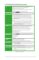
F1A75-M PRO R2.0 specifications summary APU AMD® A- & E2- series accelerated processors with AMD® Radeon™ HD 6000 series graphics, up to 4 CPU cores, FM1 package AMD® Turbo Core Technology 2.0 support * The AMD® Turbo Core Technology 2.0 support depends on the APU types. ** Refer to www.asus.com for the AMD® APU support list Chipset AMD® A75 FCH (Hudson D3) Memory Dual-channel memory architecture 4 x 240-pin DIMM slots support maximum 64GB unbuffered non-ECC DDR3 2250(O.C.
F1A75-M PRO R2.0 specifications summary USB AMD® A75 FCH southbridge: - 10 x USB 2.0/1.1 ports (8 ports at the mid-board, 2 ports at the back panel) - 4 x USB 3.0 ports (2 ports at the mid-board, 2 ports at the back panel) Asmedia® PCIe USB3.0 controller: - 2 x USB 3.0/2.
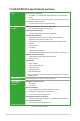
F1A75-M PRO R2.0 specifications summary Back Panel I/O ports 1 x PS/2 keyboard / mouse combo port 1 x HDMI output port 1 x DVI-D output port 1 x D-Sub output port 1 x Optical S/PDIF output port 1 x LAN (RJ-45) port 2 x USB 2.0/1.1 ports 4 x USB 3.0/2.0 ports (blue) 8-channel audio I/O ports Internal I/O connectors / buttons / switches 4 x USB 2.0/1.1 connectors support additional 8 USB 2.0/1.1 ports 1 x USB 3.0/2.0 connector supports additional 2 USB 3.0/2.0 ports 6 x SATA 6.
Package contents Check your motherboard package for the following items. KB_USB3_34 EATX12V CPU_FAN DIGI +VRM EPU PCIEX16_1 F1A75-M PRO R2.
Product introduction 1.1 Special features 1.1.1 Product highlights 1 AMD A- & E2- series accelerated processors with AMD® Radeon™ HD 6000 series graphics ® This motherboard supports AMD® A- & E2- series accelerated processor with AMD® Radeon™ HD 6000 series graphics. This revolutionary APU (Accelerated Processing Unit) combines processing power and advanced DirectX 11 graphics in one small, energy-efficient design to enable accelerated performance and an industry-leading visual experience.
1.1.2 Digital Power Design: The New Standard The world’s first Dual Intelligent Processors from ASUS pioneered the use of two onboard chips - EPU (Energy Processing Unit) and TPU (TurboV Processing Unit). New generation Dual Intelligent Processors 2 with DIGI+ VRM digital power design launch control into a new era.
1.1.3 ASUS Exclusive Features USB 3.0 Boost New ASUS USB 3.0 Boost technology supports UASP (USB Attached SCSI Protocol), the latest USB 3.0 standard. With USB 3.0 Boost technology, a USB device’s transmission speed is significantly increased up to 170%, adding to an already impressive fast USB 3.0 transfer speed. ASUS software automatically accelerates data speeds for compatible USB 3.0 peripherals without the need for any user interaction.
AI Suite II With its fast user-friendly interface, ASUS AI Suite II consolidates all the exclusive ASUS features into one simple to use software package. It allows you to supervise overclocking, energy management, fan speed control, and voltage and sensor readings. This all-in-one software offers diverse and ease to use functions, with no need to switch back and forth between different utilities. Ai Charger+ ASUS Ai Charger+, the latest Ai Charger* version, brings you to a new level of USB3.
ErP ready The motherboard is European Union´s Energy-related Products (ErP) ready, and ErP requires products to meet certain energy efficiency requirements in regards to energy consumptions. This is in line with ASUS vision of creating environment-friendly and energyefficient products through product design and innovation to reduce carbon footprint of the product and thus mitigate environmental impacts. 1.
1.3 Motherboard overview 1.3.1 Placement direction 1.3.2 Screw holes When installing the motherboard, ensure that you place it into the chassis in the correct orientation. The edge with external ports goes to the rear part of the chassis as indicated in the image below. Place eight screws into the holes indicated by circles to secure the motherboard to the chassis. DO NOT overtighten the screws! Doing so can damage the motherboard. Place this side towards the rear of the chassis. F1A75-M PRO R2.
1.3.3 Motherboard layout 1 2 1 3 4 24.4cm(9.6in) KB_USB3_34 EATX12V CPU_FAN DIGI +VRM 5 PWR_FAN 1 SB_PWR AMD® A75 PCI1 PCIEX16_2 USB78 SATA6G_2 SATA6G_4 SATA6G_6 TPU Super I/O AAFP TPU EPU F1A75-M PRO R2.0 PCIEX1_1 COM1 2 24.4cm(9.
1.3.4 Layout contents Connectors/Jumpers/Slots/LED Page 2. ATX power connectors (24-pin EATXPWR, 8-pin EATX12V) 1-25 4. 1-12 1. Power, CPU and chassis fan connectors (3-pin PWR_FAN, 4-pin CPU_FAN, and 4-pin CHA_FAN1/2) 3. AMD FM1 socket 5. TPU LED (ELED730) 6. 7. 8. 9. 1-8 DDR3 DIMM slots 1-32 EPU LED (ELED740) 1-32 EPU switch 1-31 TPU switch 1-31 MemOK! switch 1-30 10. DRAM LED (DRAM_LED) 1-32 11. Standby power LED (SB_PWR) 1-5 12. SATA 6.
1.4.1 APU installation 1 3 ASUS F1A75-M PRO R2.
1.4.2 APU heatsink and fan assembly installation Apply the Thermal Interface Material to the APU heatsink and APU before you install the heatsink and fan if necessary.
To uninstall the APU heatsink and fan assembly 1 3 2 4 5 ASUS F1A75-M PRO R2.
1.5 System memory 1.5.1 Overview This motherboard comes with four Double Data Rate 3 (DDR3) Dual Inline Memory Modules (DIMM) sockets. A DDR3 module has the same physical dimensions as a DDR2 DIMM but is notched differently to prevent installation on a DDR2 DIMM socket. DDR3 modules are developed for better performance with less power consumption. DIMM_B1 DIMM_B2 DIMM_A1 DIMM_A2 The figure illustrates the location of the DDR3 DIMM sockets: Channel F1A75-M PRO R2.
1.5.2 Memory configurations You may install 1GB, 2GB, 4GB, and 8GB unbuffered non-ECC DDR3 DIMMs into the DIMM sockets. • You may install varying memory sizes in Channel A and Channel B. The system maps the total size of the lower-sized channel for the dual-channel configuration. Any excess memory from the higher-sized channel is then mapped for single-channel operation. • We recommend that you install the memory modules from the blue slots for better overclocking capability.
F1A75-M PRO R2.0 Motherboard Qualified Vendors Lists (QVL) DDR3 2250 (O.C.) MHz capability Vendors Part No. DIMM socket support Chip NO. Timing Voltage (Optional) 1 DIMM 2 DIMMs 4 DIMMs SS/DS Chip Brand Size KINGSTON KHX2250C9D3T1K2/4GX(XMP) 4GB ( 2x 2GB ) DS - - - 1.65V • • DDR3 2200 (O.C.) MHz capability Vendors Part No. Size KINGMAX FLKE85F-B8KJA FEIH(XMP) 4GB(2 x 2GB) DS DIMM socket support (Optional) 1 DIMM 2 DIMMs 4 DIMMs 1.5V-1.7V • • SS/DS Chip Brand Chip NO.
DDR3 1600 MHz capability Vendors Part No. Size SS/ Chip Chip NO. DS Brand Timing A-Data A-Data A-Data CORSAIR CORSAIR CORSAIR CORSAIR CORSAIR CORSAIR CORSAIR CORSAIR Crucial G.SKILL G.SKILL G.SKILL G.SKILL G.SKILL G.SKILL G.SKILL G.SKILL G.
DDR3 1333 MHz capability Vendors Part No. Size SS/ Chip DS Brand Chip NO. Timing A-Data AD63I1B0823EV 2GB SS A-Data 3CCA-1509A - A-Data AXDU1333GC2G9-2G(XMP) 4GB(2 x 2GB) SS - - A-Data Apacer Apacer Apacer CORSAIR CORSAIR CORSAIR CORSAIR Crucial Crucial Crucial AD63I1C1624EV 78.A1GC6.9L1 78.A1GC6.9L1 78.B1GDE.9L10C TR3X3G1333C9 G TR3X6G1333C9 G CMD24GX3M6A1333C9(XMP) TW3X4G1333C9D G CT12864BA1339.8FF CT25664BA1339.16FF BL25664BN1337.
DDR3 1066 MHz capability Vendors Part No. Size SS/DS Chip Brand Chip NO. Timing Voltage Crucial Crucial CT12864BA1067.8FF CT25664BA1067.16FF 1GB 2GB SS DS Micron Micron 9GF22D9KPT 9HF22D9KPT 7 7 ELPIDA EBJ10UE8EDF0-AE-F 1GB SS ELPIDA J1108EDSE-DJ-F - ELPIDA EBJ21UE8EDF0-AE-F 2GB DS ELPIDA J1108EDSE-DJ-F - 1.35V(low voltage) 1.
1.5.
1.6 Expansion slots In the future, you may need to install expansion cards. The following sub‑sections describe the slots and the expansion cards that they support. Unplug the power cord before adding or removing expansion cards. Failure to do so may cause you physical injury and damage motherboard components. 1.6.1 Installing an expansion card To install an expansion card: 1.
VGA configuration PCI Express operating mode PCIe x16_1 PCIe x16_2 Single VGA/PCIe card x16 (Recommended for single VGA card) N/A Dual VGA/PCIe card x16 x4 • • • In single VGA card mode, use the PCIe 2.0 x16_1 slot (blue) for a PCI Express x16 graphics card to get better performance. We recommend that you provide sufficient power when running CrossFireX™ mode. See page 1-25 for details.
1.7 Jumpers Clear RTC RAM (CLRTC) This jumper allows you to clear the Real Time Clock (RTC) RAM in CMOS. You can clear the CMOS memory of date, time, and system setup parameters by erasing the CMOS RTC RAM data. The onboard button cell battery powers the RAM data in CMOS, which include system setup information such as system passwords. To erase the RTC RAM: F1A75-M PRO R2.0 1 2 CLRTC Normal (Default) 2 3 Clear RTC F1A75-M PRO R2.0 Clear RTC RAM 1.
1.8 Connectors 1.8.1 Rear panel ports 1 2 3 15 14 13 4 12 11 10 9 1. PS/2 Keyboard/Mouse Combo port (purple/green). This port is for a PS/2 keyboard or PS/2 mouse. 2. Optical S/PDIF Out port. This port connects an external audio output device via an optical S/PDIF cable. 3. Video Graphics Adapter (VGA) port. This 15-pin port is for a VGA monitor or other VGA-compatible devices. 4. LAN (RJ-45) port. This port allows Gigabit connection to a Local Area Network (LAN) through a network hub.
Refer to the audio configuration table below for the function of the audio ports in the 2, 4, 6, or 8-channel configuration.
1.8.2 1. Internal connectors Power, CPU and chassis fan connectors (3-pin PWR FAN, 4-pin CPU_FAN, and 4-pin CHA_FAN1/2) Connect the fan cables to the fan connectors on the motherboard, ensuring that the black wire of each cable matches the ground pin of the connector. CPU FAN PWM CPU FAN IN CPU FAN PWR GND CPU_FAN CHA_FAN1 CHA_FAN2 CHA FAN PWM CHA FAN IN CHA FAN PWR GND GND CHA FAN PWR CHA FAN IN CHA FAN DC MODE F1A75-M PRO R2.0 PWR_FAN GND +12V Rotation F1A75-M PRO R2.
3. ATX power connectors (24-pin EATXPWR, 8-pin EATX12V) These connectors are for an ATX power supply. The plugs from the power supply are designed to fit these connectors in only one orientation. Find the proper orientation and push down firmly until the connectors completely fit. GND GND GND GND +12V DC +12V DC +12V DC +12V DC EATX12V F1A75-M PRO R2.
Serial ATA 6.0 Gb/s connectors (7-pin SATA6G 1~6) These connectors are for the Serial ATA 6.0 Gb/s signal cables for Serial ATA hard disk drives and optical disc drives. If you installed Serial ATA hard disk drives, you can create a RAID 0, RAID 1, or RAID 10 configuration through the onboard controller. GND RSATA_RXP3 RSATA_RXN3 GND RSATA_TXN3 RSATA_TXP3 GND SATA6G_3 GND RSATA_RXP1 RSATA_RXN1 GND RSATA_TXN1 RSATA_TXP1 GND SATA6G_1 F1A75-M PRO R2.
6. System panel connector (20-8 pin PANEL) This connector supports several chassis-mounted functions. +5V Ground Ground Speaker SPEAKER PLED- PLED+ PLED PANEL IDE_LED Reset Ground F1A75-M PRO R2.0 PWR Ground IDE_LED+ IDE_LED- PIN 1 PWRSW RESET * Requires an ATX power supply F1A75-M PRO R2.0 System panel connector • • • • • System power LED (2-pin PLED) This 2-pin connector is for the system power LED. Connect the chassis power LED cable to this connector.
Digital audio connector (4-1 pin SPDIF_OUT) SPDIFOUT GND This connector is for an additional Sony/Philips Digital Interface (S/PDIF) port. +5V 7. F1A75-M PRO R2.0 SPDIF_OUT F1A75-M PRO R2.0 Digital audio connector Ensure that the audio device of Sound playback is Realtek High Definition Audio (the name may be different based on the OS). Go to Start > Control Panel > Sounds and Audio Devices > Sound Playback to configure the setting. The S/PDIF module is purchased separately.
USB 2.0 connectors (10-1 pin USB34, USB56, USB78, USB910) These connectors are for USB 2.0 ports. Connect the USB module cable to any of these connectors, then install the module to a slot opening at the back of the system chassis. These USB connectors comply with USB 2.0 specification that supports up to 480Mbps connection speed. USB34 USB+5V USB_P8USB_P8+ GND NC USB56 USB+5V USB_P6USB_P6+ GND NC USB910 USB+5V USB_P10USB_P10+ GND NC USB78 USB+5V USB_P4USB_P4+ GND NC 9.
1.9 Onboard switch Onboard switches allow you to fine-tune performance when working on a bare or open-case system. This is ideal for overclockers and gamers who continually change settings to enhance system performance. 1. MemOK! switch Installing DIMMs that are incompatible with the motherboard may cause system boot failure, and the DRAM_LED near the MemOK! switch lights continuously.
2. TPU switch This switch allows you to enable or disable the TPU function. TPU F1A75-M PRO R2.0 F1A75-M PRO R2.0 TPU switch 3. EPU switch This switch allows you to enable or disable the EPU function. EPU F1A75-M PRO R2.0 F1A75-M PRO R2.0 EPU switch ASUS F1A75-M PRO R2.
1.10 1. Onboard LEDs DRAM LED DRAM LED checks the DRAM in sequence during motherboard booting process. If an error is found , the LED next to the error device will continue lighting until the problem is solved. This user-friendly design provides an intuitional way to locate the root problem within a second. DRAM LED F1A75-M PRO R2.0 F1A75-M PRO R2.0 DRAM LED 2. TPU LED The TPU LED lights when the TPU switch is turned to Enable. ELED730 F1A75-M PRO R2.0 F1A75-M PRO R2.0 TPU LED 3.
1.11 Software support 1.11.1 Installing an operating system This motherboard supports Windows® XP / Vista / Windows® 7 / Windows® 8 Operating Systems (OS). Always install the latest OS version and corresponding updates to maximize the features of your hardware. 1.11.2 • Motherboard settings and hardware options vary. Refer to your OS documentation for detailed information.
1-34 Chapter 1: Product introduction
BIOS information 2.1 Managing and updating your BIOS 2 Save a copy of the original motherboard BIOS file to a USB flash disk in case you need to restore the BIOS in the future. Copy the original motherboard BIOS using the ASUS Update utility. 2.1.1 ASUS Update utility The ASUS Update is a utility that allows you to manage, save, and update the motherboard BIOS in Windows® environment. • ASUS Update requires an Internet connection either through a network or an Internet Service Provider (ISP).
Updating from the Internet a. Select Update BIOS from the Internet, then click Next. b. Select the ASUS FTP site nearest you to avoid network traffic, then click Next. c. From the FTP site, select the BIOS version that you wish to download then click Next. The ASUS Update utility is capable of updating itself through the Internet. Always update the utility to avail all its features. Updating from a BIOS file 3. a. Select Update BIOS from file, then click Next. b.
2.1.3 ASUS CrashFree BIOS 3 utility The ASUS CrashFree BIOS 3 is an auto recovery tool that allows you to restore the BIOS file when it fails or gets corrupted during the updating process. You can restore a corrupted BIOS file using the motherboard support DVD or a USB flash drive that contains the updated BIOS file. • Before using this utility, rename the BIOS file in the removable device into F1A75MP2.CAP. • The BIOS file in the support DVD may not be the latest version.
2.1.4 ASUS BIOS Updater The ASUS BIOS Updater allows you to update BIOS in DOS environment. This utility also allows you to copy the current BIOS file that you can use as a backup when the BIOS fails or gets corrupted during the updating process. The succeeding utility screens are for reference only. The actual utility screen displays may not be same as shown. Before updating BIOS 1. Prepare the motherboard support DVD and a USB flash drive in FAT32/16 format and single partition. 2.
Updating the BIOS file To update the BIOS file using BIOS Updater 1. At the FreeDOS prompt, type bupdater /pc /g and press . D:\>bupdater /pc /g 2. The BIOS Updater screen appears as below. ASUSTek BIOS Updater for DOS V1.30 Current ROM BOARD: F1A75-M PRO R2.0 VER: 0204 DATE: 06/04/2012 Update ROM BOARD: Unknown VER: Unknown DATE: Unknown PATH: A:\ F1A75MP2.CAP A: Note [Enter] Select or Load [Up/Down/Home/End] Move 3.
2.2 BIOS setup program Use the BIOS Setup program to update the BIOS or configure its parameters. The BIOS screens include navigation keys and brief online help to guide you in using the BIOS Setup program. Entering BIOS Setup at startup To enter BIOS Setup at startup: • Press during the Power-On Self Test (POST). If you do not press , POST continues with its routines. Entering BIOS Setup after POST To enter BIOS Setup after POST: • Press ++ simultaneously.
BIOS menu screen The BIOS setup program can be used under two modes: EZ Mode and Advanced Mode. You can change modes from the Exit menu or from the Exit/Advanced Mode button in the EZ Mode/Advanced Mode screen. EZ Mode By default, the EZ Mode screen appears when you enter the BIOS setup program. The EZ Mode provides you an overview of the basic system information, and allows you to select the display language, system performance mode and boot device priority.
Advanced Mode The Advanced Mode provides advanced options for experienced end-users to configure the BIOS settings. The figure below shows an example of the Advanced Mode. Refer to the following sections for the detailed configurations. To access the EZ Mode, click Exit, then select ASUS EZ Mode.
Menu items The highlighted item on the menu bar displays the specific items for that menu. For example, selecting Main shows the Main menu items. The other items (Ai Tweaker, Advanced, Monitor, Boot, Tool, and Exit) on the menu bar have their respective menu items. Back button This button appears when entering a submenu. Press or use the USB mouse to click this button to return to the previous menu screen.
2.3 Main menu The Main menu screen appears when you enter the Advanced Mode of the BIOS Setup program. The Main menu provides you an overview of the basic system information, and allows you to set the system date, time, language, and security settings.
Administrator Password If you have set an administrator password, we recommend that you enter the administrator password for accessing the system. Otherwise, you might be able to see or change only selected fields in the BIOS setup program. To set an administrator password: 1. Select the Administrator Password item and press . 2. From the Create New Password box, key in a password, then press . 3. Confirm the password when prompted. To change an administrator password: 1.
2.4 Ai Tweaker menu The Ai Tweaker menu items allow you to configure overclocking-related items. Be cautious when changing the settings of the Ai Tweaker menu items. Incorrect field values can cause the system to malfunction. The configuration options for this section vary depending on the CPU and DIMM model you installed on the motherboard.
Target CPU Speed : xxxxMHz Displays the current CPU speed. Target DRAM Speed : xxxxMHz Displays the current DRAM speed. 2.4.1 Ai Overclock Tuner [Auto] Allows you to select the CPU overclocking options to achieve the desired CPU internal frequency. Select any of these preset overclocking configuration options: [Auto] Loads the optimal settings for the system. [Manual] Allows you to individually set overclocking parameters. [D.O.C.P.] Allows you to select a DRAM O.C.
2.4.5 OC Tuner 2.4.6 DRAM Timing Control OC Tuner automatically overclocks the frequency and voltage of CPU and DRAM for enhancing the system performance. Press and select OK to start automatic overclocking. The sub-items in this menu allow you to set the DRAM timing control features. Use the <+> and <-> keys to adjust the value. To restore the default setting, type [auto] using the keyboard and press .
2.4.8 DRAM Voltage [Auto] 2.4.9 SB 1.1V Voltage [Auto] 2.4.10 1.1Vsb Voltage [Auto] 2.4.11 APU1.2V Voltage [Auto] 2.4.12 VDDA Voltage [Auto] Allows you to set the DRAM voltage. The values range from 1.35V to 2.30V with a 0.01V interval. Allows you to set the Southbridge 1.1V voltage. The values range from 1.1V to 1.4V with a 0.01V interval. Allows you to set the 1.1Vsb voltage. The values range from 1.1000V to 1.2000V with a 0.1V interval. Allows you to set the APU (Accelerated Processor Unit) 1.
CPU/NB Current Capability [100%] This item provides wider total power range for overclocking. A higher value brings a wider total power range and extends the overclocking frequency range simultaneously. Configuration options: [100%] [110%] [120%] [130%] CPU Power Phase Control [Standard] Phase number is the number of working VRM phase. Increasing phase number under heavy system loading to get more transient and better thermal performance.
2.5 Advanced menu The Advanced menu items allow you to change the settings for the CPU and other system devices. Be cautious when changing the settings of the Advanced menu items. Incorrect field values can cause the system to malfunction. EFI BIOS Utility - Advanced Mode Ai Tweaker Main Advanced > CPU Configuration Exit Monitor Boot Tool CPU Configuration Parameters > SATA Configuration > USB Configuration > NB Configuration > Onboard Devices Configuration > APM > Network Stack 2.5.
2.5.2 SATA Configuration While entering Setup, the BIOS automatically detects the presence of SATA devices. The SATA Port items show Not Present if no SATA device is installed to the corresponding SATA port. OnChip SATA Channel [Enabled] Enables or disables onboard channel SATA port. Configuration options: [Disabled] [Enabled] OnChip SATA Type [IDE] Allows you to set the SATA configuration.
2.5.3 USB Configuration The items in this menu allow you to change the USB-related features. The USB Devices item shows the auto-detected values. If no USB device is detected, the item shows None. Legacy USB Support [Enabled] [Enabled] [Disabled] [Auto] Enables the support for USB devices on legacy operating systems (OS). The USB devices can be used only for the BIOS setup program. Allows the system to detect the presence of USB devices at startup. If detected, the USB controller legacy mode is enabled.
2.5.5 Onboard Devices Configuration HD Audio Device [Enabled] [Enabled] [Disabled] Enables the High Definition Audio Controller. Disables the controller. The following two items appear only when you set the HD Audio Device item to [Enabled]. Front Panel Type [HD] Allows you to set the front panel audio connector (AAFP) mode to legacy AC’97 or highdefinition audio depending on the audio standard that the front panel audio module supports.
2.5.6 APM Restore AC Power Loss [Power Off] [Power On] [Power Off] [Last State] The system goes into on state after an AC power loss. The system goes into off state after an AC power loss. The system goes into either off or on state, whatever the system state was before the AC power loss. Power On By PS/2 Keyboard [Disabled] [Disabled] [Space Bar] [Ctrl-Esc] [Power Key] Disables the Power On by a PS/2 keyboard. Sets the Space Bar on the PS/2 keyboard to turn on the system.
2.5.7 Network Stack Network Stack [Disable Link] This item allows user to disable or enable the UEFI network stack. Configuration options: [Disable Link] [Enabled] Ipv4 PXE Support [Enabled] This item appears only when you set the Network Stack item to [Enabled]. When this item is disabled, the IPV4 PXE boot option will not be created. Configuration options: [Disable Link] [Enabled] Ipv6 PXE Support [Enabled] This item appears only when you set the Network Stack item to [Enabled].
2.6.1 CPU Temperature / MB Temperature [xxxºC/xxxºF] The onboard hardware monitor automatically detects and displays the CPU and motherboard temperatures. Select Ignore if you do not wish to display the detected temperatures. 2.6.2 CPU / Chassis / Power Fan Speed [xxxx RPM] or [Ignore] / [N/A] The onboard hardware monitor automatically detects and displays the CPU / chassis / power fan speeds in rotations per minute (RPM). If the fan is not connected to the motherboard, the field shows N/A.
2.6.4 [Disabled] [Enabled] Chassis Q-Fan Control [Disabled] Disables the Chassis Q-Fan control feature. Enables the Chassis Q-Fan control feature. Chassis Fan Speed Low Limit [600 RPM] This item appears only when you enable the Chassis Q-Fan Control feature and allows you to disable or set the chassis fan warning speed.
2.7 Boot menu The Boot menu items allow you to change the system boot options. UEFI BIOS Utility - Advanced Mode Ai Tweaker Main Exit Advanced Bootup NumLock State Full Screen Logo Wait For ‘F1’ If Error Option ROM Messages Monitor On Boot Tool Select the keyboard NumLock state Enabled Enabled Force BIOS Setup Mode EZ Mode UEFI/Legacy Boot Enabled both...
2.7.4 [Force BIOS] Option ROM Messages [Force BIOS] [Keep Current] The third-party ROM messages will be forced to display during the boot sequence. The third-party ROM messages will be displayed only if the third-party manufacturer had set the add-on device to do so. 2.7.5 Setup Mode [EZ Mode] 2.7.6 UEFI/Legacy Boot [Enabled both UEFI and Legacy] 2.7.7 PCI ROM Priority [Legacy ROM] 2.7.
2.8 Tools menu The Tools menu items allow you to configure options for special functions. Select an item then press to display the submenu. EFI BIOS Utility - Advanced Mode Ai Tweaker Main Advanced Exit Monitor Boot Tool Be used to update BIOS > ASUS EZ Flash 2 Utility > ASUS O.C. Profile > ASUS SPD Information 2.8.1 ASUS EZ Flash 2 Utility Allows you to run ASUS EZ Flash 2. Press [Enter] to launch the ASUS EZ Flash 2 screen. For more details, see section 2.1.2 ASUS EZ Flash 2. 2.8.
2.9 Exit menu The Exit menu items allow you to load the optimal default values for the BIOS items, and save or discard your changes to the BIOS items. You can access the EZ Mode from the Exit menu. Exit Load Optimized Defaults Save Changes & Reset Discard Changes & Exit ASUS EZ Mode Launch EFI Shell from filesystem device Load Optimized Defaults This option allows you to load the default values for each of the parameters on the Setup menus.
Appendices Notices Federal Communications Commission Statement This device complies with Part 15 of the FCC Rules. Operation is subject to the following two conditions: • • This device may not cause harmful interference. This device must accept any interference received including interference that may cause undesired operation. This equipment has been tested and found to comply with the limits for a Class B digital device, pursuant to Part 15 of the FCC Rules.
Canadian Department of Communications Statement This digital apparatus does not exceed the Class B limits for radio noise emissions from digital apparatus set out in the Radio Interference Regulations of the Canadian Department of Communications. This class B digital apparatus complies with Canadian ICES-003.
ASUS contact information ASUSTeK COMPUTER INC. Address Telephone Fax E-mail Web site Technical Support Telephone Online support 15 Li-Te Road, Peitou, Taipei, Taiwan 11259 +886-2-2894-3447 +886-2-2890-7798 info@asus.com.tw www.asus.com.tw +86-21-38429911 support.asus.
A-4 Appendices (510)739-3777/(510)608-4555 800 Corporate Way, Fremont, CA 94539. Asus Computer International Signature : Date : Representative Person’s Name : May 29, 2012 Steve Chang / President This device complies with part 15 of the FCC Rules. Operation is subject to the following two conditions: (1) This device may not cause harmful interference, and (2) this device must accept any interference received, including interference that may cause undesired operation.