BIOS Manual Motherboard STRIX Z270G GAMING
E12643 First Edition April 2017 Copyright© 2017 ASUSTeK COMPUTER INC. All Rights Reserved. No part of this manual, including the products and software described in it, may be reproduced, transmitted, transcribed, stored in a retrieval system, or translated into any language in any form or by any means, except documentation kept by the purchaser for backup purposes, without the express written permission of ASUSTeK COMPUTER INC. (“ASUS”).
Contents 1.1 Knowing BIOS................................................................................................ 4 1.2 BIOS setup program...................................................................................... 5 1.2.1 EZ Mode......................................................................................... 6 1.2.2 Advanced Mode.............................................................................. 7 1.2.3 QFan Control..............................................
BIOS Setup 1.1 Knowing BIOS The new ASUS UEFI BIOS is a Unified Extensible Interface that complies with UEFI architecture, offering a user-friendly interface that goes beyond the traditional keyboardonly BIOS controls to enable a more flexible and convenient mouse input. You can easily navigate the new UEFI BIOS with the same smoothness as your operating system. The term “BIOS” in this user manual refers to “UEFI BIOS” unless otherwise specified.
1.2 BIOS setup program Use the BIOS Setup to update the BIOS or configure its parameters. The BIOS screen includes navigation keys and brief onscreen help to guide you in using the BIOS Setup program. Entering BIOS at startup To enter BIOS Setup at startup, press or during the Power-On Self Test (POST). If you do not press or , POST continues with its routines. Entering BIOS Setup after POST To enter BIOS Setup after POST: • Press ++ simultaneously.
1.2.1 EZ Mode The EZ Mode provides you an overview of the basic system information, and allows you to select the display language, system performance, mode and boot device priority. To access the Advanced Mode, select Advanced Mode or press the hotkey for the advanced BIOS settings. The default screen for entering the BIOS setup program can be changed. Refer to the Setup Mode item in section Boot menu for details. Displays the system properties of the selected mode.
1.2.2 Advanced Mode The Advanced Mode provides advanced options for experienced end-users to configure the BIOS settings. The figure below shows an example of the Advanced Mode. Refer to the following sections for the detailed configurations. To switch from EZ Mode to Advanced Mode, click Advanced Mode(F7) or press the hotkey.
Menu bar The menu bar on top of the screen has the following main items: My Favorites For saving the frequently-used system settings and configuration. For changing the basic system configuration Main Ai Tweaker For changing the overclocking settings Advanced For changing the advanced system settings Monitor For displaying the system temperature, power status, and changing the fan settings.
Search on FAQ Move your mouse over this button to show a QR code, scan this QR code on your mobile device to connect to the BIOS FAQ web page of the ASUS support website. You can also scan the following QR code: Hot keys This button above the menu bar contains the navigation keys for the BIOS setup program. Use the navigation keys to select items in the menu and change the settings. Scroll bar A scroll bar appears on the right side of a menu screen when there are items that do not fit on the screen.
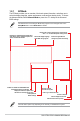
1.2.3 QFan Control The QFan Control allows you to set a fan profile or manually configure the operating speed of your CPU and chassis fans.
Configuring fans manually Select Manual from the list of profiles to manually configure your fans’ operating speed. Speed points Select to manually configure your fans To configure your fans: 1. Select the fan that you want to configure and to view its current status. 2. Click and drag the speed points to adjust the fans’ operating speed. 3. Click Apply to save the changes then click Exit (ESC).
1.2.4 EZ Tuning Wizard EZ Tuning Wizard allows you to easily overclock your CPU and DRAM, computer usage, and CPU fan to their best settings. You can also set RAID in your system using this feature. OC setup RAID setup OC Tuning To start OC Tuning: 12 1. Press on your keyboard or click EZ Tuning Wizard screen. 2. Click OC then click Next. 3. Select a PC scenario Daily Computing or Gaming/Media Editing, then click Next.
4. Select a Main Cooling System BOX cooler, Tower cooler, Water cooler, or I’m not sure, then click Next. 5. After selecting the Main Cooling System, click Next then click Yes to start the OC Tuning. Creating RAID To create RAID: 1. Press on your keyboard or click EZ Tuning Wizard screen. 2. Click RAID then click Next. 3. from the BIOS screen to open • Ensure that your HDDs have no existing RAID volumes. • Ensure to connect your HDDs to Intel® SATA connectors.
4. Select the type of storage for your RAID, Easy Backup or Super Speed, then click Next. a. For Easy Backup, click Next then select from Easy Backup (RAID 1) or Easy Backup (RAID 10). You can only select Easy Backup (RAID 10) if you connect four (4) HDDs. b. 14 For Super Speed, click Next then select from Super Speed (RAID 0) or Super Speed (RAID 5). 5. After selecting the type of RAID, click Next then click Yes to continue the RAID setup. 6.
1.3 My Favorites My Favorites is your personal space where you can easily save and access your favorite BIOS items. My Favorites comes with several performance, power saving, and fast boot related items by default. You can personalize this screen by adding or removing items.
Adding items to My Favorites To add BIOS items: 1. Press on your keyboard or click MyFavorites(F3) from the BIOS screen to open Setup Tree Map screen. 2. On the Setup Tree Map screen, select the BIOS items that you want to save in My Favorites screen. Main menu panel Selected shortcut items Submenu panel Delete all favorite items Recover to default favorite items 3. Select an item from main menu panel, then click the submenu that you want to save as or press on your keyboard.
1.4 Main menu The Main menu screen appears when you enter the Advanced Mode of the BIOS Setup program. The Main menu provides you an overview of the basic system information, and allows you to set the system date, time, language, and security settings. Security The Security menu items allow you to change the system security settings. • If you have forgotten your BIOS password, erase the CMOS Real Time Clock (RTC) RAM to clear the BIOS password. See section 1.1.
Administrator Password If you have set an administrator password, we recommend that you enter the administrator password for accessing the system. Otherwise, you might be able to see or change only selected fields in the BIOS setup program. To set an administrator password: 1. Select the Administrator Password item and press . 2. From the Create New Password box, key in a password, then press . 3. Re-type to confirm the password then select OK. To change an administrator password: 1.
1.5 Ai Tweaker menu The Ai Tweaker menu items allow you to configure overclocking-related items. Be cautious when changing the settings of the Ai Tweaker menu items. Incorrect field values can cause the system to malfunction. The configuration options for this section vary depending on the CPU and DIMM model you installed on the motherboard. Scroll down to display other BIOS items.
When the Ai Overclock Tuner is set to [Manual] or [XMP], the following items appear. BCLK Frequency This item allows you to set the BCLK (base clock) frequency to enhance the system performance. Use the <+> or <-> to adjust the value. The values range from 40.0 MHz to 650.0 MHz. We recommend you to set the value based on the CPU specification, as high BCLK frequencies may damage the CPU permanently.
3-Core Ratio Limit Enter [Auto] to apply the CPU default Turbo Ratio setting or manually assign a 3-core ratio limit that must be higher than or equal to the 4-core ratio limit. If you assign a value for 3-Core Ratio Limit, do not set the 1-Core Ratio Limit and 2-Core Ratio Limit to [Auto]. 4-Core Ratio Limit Enter [Auto] to apply the CPU default Turbo Ratio setting or manually assign a 4-core ratio limit that must be lower than or equal to the 4-core ratio limit.
EPU Power Saving Mode The ASUS EPU (Energy Processing Unit) sets the CPU in its minimum power consumption settings. Enabling this item will apply lower CPU Core/Cache Voltage and help save energy consumption. Set this item to disabled if you are over clocking the system. Configuration options: [Disabled] [Enabled] Load CPU 5G OC Profile This 5G OC Profile allows you to easily overclock the Intel 7th gen Core Processor (K-series only) to 5GHz.
DRAM WRITE Recovery Time Configuration options: [Auto] [1] – [31] DRAM READ to PRE Time Configuration options: [Auto] [1] – [15] DRAM FOUR ACT WIN Time Configuration options: [Auto] [1] – [63] DRAM WRITE to READ Delay Configuration options: [Auto] [1] – [15] DRAM WRITE to READ Delay L Configuration options: [Auto] [1] – [15] DRAM WRITE to READ Delay S Configuration options: [Auto] [1] – [15] DRAM CKE Minimum Pulse Width Configuration options: [Auto] [0] – [15] DRAM Write Latency Configuration options: [Auto
ODT_WRITE_DURATION Configuration options: [Auto] [0] - [7] ODT_WRITE_DELAY Configuration options: [Auto] [0] - [7] Data Rising Slope Configuration options: [Auto] [0] - [15] Data Rising Slope Offset Configuration options: [Auto] [0] - [1] Cmd Rising Slope Configuration options: [Auto] [0] - [15] Cmd Rising Slope Offset Configuration options: [Auto] [0] - [1] Ctl Rising Slope Configuration options: [Auto] [0] - [15] Ctl Rising Slope Offset Configuration options: [Auto] [0] - [1] Clk Rising Slope Configuratio
DRAM RTL (CHA DIMM1 Rank0) Configuration options: [Auto] [0] - [127] DRAM RTL (CHA DIMM1 Rank1) Configuration options: [Auto] [0] - [127] DRAM RTL (CHB DIMM0 Rank0) Configuration options: [Auto] [0] - [127] DRAM RTL (CHB DIMM0 Rank1) Configuration options: [Auto] [0] - [127] DRAM RTL (CHB DIMM1 Rank0) Configuration options: [Auto] [0] - [127] DRAM RTL (CHB DIMM1 Rank1) Configuration options: [Auto] [0] - [127] DRAM IOL (CHA DIMM0 Rank0) Configuration options: [Auto] [0] - [15] DRAM IOL (CHA DIMM0 Rank1) Con
Third Timings tRDRD_sg Configuration options: [Auto] [0] - [63] tRDRD_dg Configuration options: [Auto] [0] - [63] tRDWR_sg Configuration options: [Auto] [0] - [63] tRDWR_dg Configuration options: [Auto] [0] - [63] tWRWR_sg Configuration options: [Auto] [0] - [63] tWRWR_dg Configuration options: [Auto] [0] - [63] tWRRD_sg Configuration options: [Auto] [0] - [127] tWRRD_dg Configuration options: [Auto] [0] - [63] tRDRD_dr Configuration options: [Auto] [0] - [63] tRDRD_dd Configuration options: [Auto] [0] - [6
tREFIX9 Configuration options: [Auto] [0] - [127] OREF_RI Configuration options: [Auto] [0] – [255] Misc. MRC Fast Boot Allows you to enable, disable or automatically set the MRC fast boot. Configuration options: [Auto] [Enabled] [Disabled] DRAM CLK Period Configuration options: [Auto] [1] – [40] Memory Scrambler Set this item to enable or disable memory scrambler support. Configuration options: [Enabled] [Disabled] Channel A DIMM Control Allows you to enable or disable the Channel A DIMM slots.
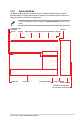
External DIGI+ Power Control CPU Load-line Calibration Load-line is defined by Intel® specification and affects CPU power voltage. The CPU working voltage decreases proportionally to CPU loading. Higher load-line calibration could get higher voltage and good overclocking performance, but increases the CPU and VRM thermal conditions. Select from levels 1 to 7 to adjust the load-line slope.
The following item appears only when the CPU VRM Switching Frequency is set to [Auto]. VRM Spread Spectrum This item allows to enhance the system stability. Configuration options: [Auto] [Disabled] [Enabled] CPU Power Duty Control DIGI + VRM Duty Control adjusts the current of every VRM phase and the thermal conditions of every phase component. [T. Probe] Select to set the VRM thermal balance mode. [Extreme] Select to set the VRM current balance mode. DO NOT remove the thermal module.
CPU Graphics Switching Frequency The switching frequency will affect the CPU Graphics transient response speed and the component thermal production. Configuration options: [Auto] [Manual] DO NOT remove the thermal module. The thermal conditions should be monitored. The following item appears only when you set the CPU Graphics Switching Frequency to [Manual]. Fixed CPU Graphics Switching Frequency(KHz) This item allows you to set a higher frequency for a quicker transient response speed.
Turbo Mode Parameters The following items appear only when you set the Turbo Mode to [Enabled]. Long Duration Package Power Limit As know as the power limit 1 in Watts. The default value will be the TDP (thermal design power). The turbo ratio can be maintained for a duration to exceed the TDP for the maximum system performance. Configuration options: [Auto] [1] - [4095] Package Power Time Window As know as the power limit 1 in Watts.
BCLK Spread Spectrum This item allows you to reduce the EMI. Disable to get more accurate base clocks. Configuration options: [Auto] [Disabled] BCLK Frequency Slew Rate Configuration options: [Auto] [40us/MHz] [80us/MHz] VPPDDR Voltage Configuration options: [Auto] [1.86500] - [2.70000] DMI Voltage Configuration options: [Auto] [0.30000] - [1.90000] Internal PLL Voltage Configuration options: [Auto] [0.900] - [1.845] CPU Core/Cache Current Limit Max.
CPU Core/Cache Voltage Configures the mode of Voltage fed to the cores of the processor. Configuration options: [Auto] [Manual Mode] [Offset Mode] [Adaptive Mode] The following items appear only when you set the CPU Core/Cache Voltage to [Manual Mode]. CPU Core Voltage Override Allows you to configure the CPU Core voltage. Configuration options: [Auto] [0.600] - [1.700] The following items appear only when you set the CPU Core/Cache Voltage to [Offset Mode].
CPU Graphics Voltage Mode [Auto] Configures the mode of Voltage fed to the CPU graphics. Configuration options: [Auto] [Manual Mode] [Offset Mode] The following item appears only when you set the CPU Graphics Voltage Mode to [Manual Mode]. CPU Graphics Voltage Override Allows you to configure the CPU Graphics Voltage. Configuration options: [Auto] [0.600] - [1.700] The following items appear only when you set the CPU Graphics Voltage Mode to [Offset Mode].
DRAM DATA REF Voltage on CHB DIMM0 Rank0 BL0-7 Configures the DRAM Data REF Voltage. Configuration options: [Auto] [0] - [63] DRAM DATA REF Voltage on CHB DIMM0 Rank1 BL0-7 Configures the DRAM Data REF Voltage. Configuration options: [Auto] [0] - [63] DRAM DATA REF Voltage on CHB DIMM1 Rank0 BL0-7 Configures the DRAM Data REF Voltage. Configuration options: [Auto] [0] - [63] DRAM DATA REF Voltage on CHB DIMM1 Rank1 BL0-7 Configures the DRAM Data REF Voltage.
1.6 Advanced menu The Advanced menu items allow you to change the settings for the CPU and other system devices. Be cautious when changing the settings of the Advanced menu items. Incorrect field values can cause the system to malfunction.
1.6.1 CPU Configuration The items in this menu show the CPU-related information that the BIOS automatically detects. The items in this menu may vary based on the CPU installed. Hyper-threading This item allows a hyper-threading processor to appear as two logical processors, allowing the operating system to schedule two threads or processors simultaneously. Configuration options: [Disabled] [Enabled] Thermal Monitor This item allows you to enable or disable the Thermal Monitor.
Hardware Prefetcher This item allows the CPU to prefetch commands and data in the L2 cache, reduces the DRAM loading time and improves the system performance. Configuration options: [Disabled] [Enabled] Adjacent Cache Line Prefetch This item allows the mid level cache (L2) to prefetch adjacent cache lines, reducing the DRAM loading time and improves the system performance.
CPU C-states This item allows you to set the power saving of the CPU states. Configuration options: [Auto] [Disabled] [Enabled] The following items appear only when you set the CPU C-states to [Enabled]. Enhanced C-States When enabled, CPU will switch to minimum speed when all cores enter C-State. Configuration options: [Enabled] [Disabled] CPU C3 Report This item allows you to disable or enable the CPU C3 report to the operating system.
1.6.2 Platform Misc Configuration The items in this menu allow you to configure the platform-related features. PCI Express Native Power Management This item allows you to enhance the power saving feature of PCI Express and perform ASPM operations in the operating system. Configuration options: [Disabled] [Enabled] The following item appears only when you set the PCI Express Native Power Management to [Enabled].
PEG - ASPM This item allows you to select the ASPM state for energy-saving conditions, or use the ASUS optimized energy saving profile. Configuration options: [Disabled] [Auto] [ASPM L0s] [ASPM L1] [ASPM L0sL1] 1.6.3 System Agent (SA) Configuration VT-d Allows you to enable virtualization technology function on memory control hub. Configuration options: [Enabled] [Disabled] Graphics Configuration This item allows you to select a primary display from CPU and PCIe graphical devices.
DMI/OPI Configuration This item allows you to control various DMI (direct media interface) functions. DMI Max Link Speed Set DMI Speed Gen1/Gen2/Gen3 Configuration options: [Auto] [Gen1] [Gen2] [Gen3] PEG Port Configuration This item allows you to configure the PEG Port settings. PCIEX16/X8_1 Link Speed This item allows you to configure the PCIEX16/X8_1 slot. Configuration options: [Auto] [Gen1] [Gen2] [Gen3] PCIEX8_2 Link Speed This item allows you to configure the PCIEX8_2 slot.
1.6.5 PCH Storage Configuration While entering Setup, the BIOS automatically detects the presence of SATA devices. The SATA Port items show Empty if no SATA device is installed to the corresponding SATA port. Scroll down to display the other BIOS items. Hyper kit1 Mode Disable this option for M.2_1 devices. Enable this option for “ASUS Hyper kit” card. Configuration options: [Disabled] [Enabled] SATA Controller(s) This item allows you to enable or disable the SATA Device.
S.M.A.R.T. Status Check S.M.A.R.T. (Self-Monitoring, Analysis and Reporting Technology) is a monitoring system that shows a warning message during POST (Power-on Self Test) when an error occurs in the hard disks. Configuration options: [On] [Off] Aggressive LPM support This item is designed for LPM (link power management) support with a better energy saving conditions. When disabled, the hot plug function of SATA ports are disabled.
1.6.7 Onboard Devices Configuration Scroll down to view the other BIOS items. HD Audio Controller This item allows you to use the Azalia High Definition Audio Controller Configuration options: [Disabled] [Enabled] M.2_1 Configuration: [Auto][SATA mode][PCIE mode] [Auto] Auto-detects the M.2 device mode. If a SATA device is detected, SATA6G_1 will be disabled. [SATA mode] Only supports M.2 SATA devices. Please note that SATA6G_1 port cannot be used in this mode. [PCIE mode] Only supports M.
RGB LED lighting This item allows you to turn the RGB LED lighting on or off. Configuration options: [On] [Off] The following item appears only when you set the RGB LED lighting to [On]. In sleep, hibernate and soft off states This item allows you to turn the RGB LED lighting on or off in S3(sleep), S4(hibernate) and S5(soft off) states. Configuration options: [On] [Off] Bluetooth Controller This item allows you to enable or disable the Bluetooth Controller.
1.6.8 APM Configuration ErP Ready This item allows you to switch off some power at S4+S5 or S5 to get the system ready for ErP requirement. When set to [Enabled], all other PME options are switched off. Configuration options: [Disabled] [Enabled (S4+S5] [Enabled (S5)] Restore AC Power Loss This item allows your system to go to ON state, OFF state, or both states after an AC power loss. When setting your system to [Last State], it goes to the previous state before the AC power loss.
1.6.9 Network Stack Configuration Network stack This item allows you to disable or enable the UEFI network stack. Configuration options: [Disable] [Enable] The following item appears only when you set the Network Stack to [Enabled]. Ipv4/Ipv6 PXE Support This item allows you to enable or disable the Ipv4/Ipv6 PXE wake event. Configuration options: [Disabled] [Enabled] 1.6.10 HDD/SSD SMART Information This menu displays the SMART information of the connected devices.
1.6.11 USB Configuration The items in this menu allow you to change the USB-related features. The Mass Storage Devices item shows the auto-detected values. If no USB device is detected, the item shows None. Legacy USB Support [Enabled] Your system supports the USB devices in legacy operating systems. [Disabled] Your USB devices can be used for BIOS setup only and cannot be recognized in the boot devices list. [Auto] Your system automatically detects the presence of USB devices at startup.
1.7 Monitor menu The Monitor menu displays the system temperature/power status, and allows you to change the fan settings. Scroll down to display the other BIOS items. CPU Temperature, Motherboard Temperature, PCH Temperature, T_Sensor1 Temperature [xxx°C/xxx°F] The onboard hardware monitor automatically detects and displays the CPU, motherboard, PCH, and T_Sensor1 temperatures. Select [Ignore] if you do not wish to display the detected temperatures.
CPU Q-Fan Control This item allows you to set the CPU Q-Fan operating mode. [Auto] Detects the type of CPU fan installed and automatically switches the control modes. [PWM Mode] Enables the CPU Q-Fan Control feature in PWM mode for 4-pin CPU fan. [DC Mode] Enables the CPU Q-Fan Control feature in DC mode for 3-pin CPU fan. [Disabled] Disables the Q-Fan Control. The following items appear only when you set the CPU Q-Fan Control to [Auto], [PWM Mode], and [DC Mode].
CPU Fan Middle. Duty Cycle(%) Use the <+> or <-> keys to adjust the CPU fan middle duty cycle. CPU Lower Temperature Use the <+> or <-> keys to adjust the lower limit of the CPU temperature. The CPU fan will operate at the minimum duty cycle when the CPU temperature is lower than the limit. CPU Fan Min. Duty Cycle(%) Use the <+> and <-> keys to adjust the minimum CPU fan duty cycle. When the CPU temperature is lower than the lower limit, the CPU fan will operate at the minimum duty cycle.
Chassis Fan 1-2 Profile This item allows you to set the appropriate performance level of the chassis fan. [Standard] Sets to [Standard] to make the chassis fan automatically adjust depending on the chassis temperature. [Silent] Sets to [Silent] to minimize the fan speed for quiet chassis fan operation. [Turbo] Sets to [Turbo] to achieve maximum chassis fan speed. [Manual] Sets to [Manual] to assign detailed fan speed control parameters.
W_PUMP+ Control [Disabled] Disable the W_PUMP+ control feature. [Auto] Detects the type of W_PUMP+ installed and automatically switches the control modes. [DC mode] Enable the W_PUMP+ control in DC mode for 3-pin chassis fan. [PWM mode] Enable the W_PUMP+ control in PWM mode for 4-pin chassis fan. The following items appear only when you set the W_PUMP+ Control to [Auto], [DC mode] or [PWM mode]. W_PUMP+ Upper Temperature Use the <+> or <-> keys to adjust the upper limit of the W_PUMP+ temperature.
1.8 Boot menu The Boot menu items allow you to change the system boot options. Fast Boot [Disabled] Allows your system to go back to its normal boot speed. [Enabled] Allows your system to accelerate the boot speed. The following items appear only when you set the Fast Boot to [Enabled]. Next Boot after AC Power Loss [Normal Boot] Returns to normal boot on the next boot after an AC power loss. [Fast Boot] Accelerates the boot speed on the next boot after an AC power loss.
The following item appears only when you set the Boot Logo Display to [Disabled]. Post Report This item allows you to select a desired POST report waiting time. Configuration options: [1 sec] - [10 sec] [Until Press ESC] Boot up NumLock State This item allows you to enable or disable power-on state of the NumLock.
The following items appear only when you set the Launch CSM to [Enabled]. Boot Device Control This item allows you to select the type of devices that you want to boot. Configuration options: [UEFI and Legacy OPROM] [Legacy OPROM only] [UEFI only] Boot from Network Devices This item allows you to select the type of network devices that you want to launch.
Save to file This item allows you to save the PK to a USB storage device. Set New key This item allows you to load the downloaded PK from a USB storage device. Delete key This item allows you to delete the PK from your system. Once the PK is deleted, all the system’s Secure Boot keys will not be active. Configuration options: [Yes] [No] The PK file must be formatted as a UEFI variable structure with time-based authenticated variable.
Delete key This item allows you to delete the db file from your system. Configuration options: [Yes] [No] The db file must be formatted as a UEFI variable structure with time-based authenticated variable. DBX Management The dbx (Revoked Signature database) lists the forbidden images of db items that are no longer trusted and cannot be loaded. Save to file This item allows you to save the dbx to a USB storage device. Set New key This item allows you to load the downloaded dbx from a USB storage device.
1.9 Tool menu The Tool menu items allow you to configure options for special functions. Select an item then press to display the submenu. Setup Animator This item allows you to enable or disable the Setup animator. Configuration options: [Disabled] [Enabled] 1.9.1 ASUS EZ Flash 3 Utility This item allows you to run ASUS EZ Flash 3. When you press , a confirmation message appears. Use the left/right arrow key to select between [Yes] or [No], then press to confirm your choice.
Check the ASUS support site for a full list of SSDs tested with Secure Erase. The drive may become unstable if you run Secure Erase on an incompatible SSD. • The time to erase the contents of your SSD may take a while depending on its size. Do not turn off the system during the process. • Secure Erase is only supported on Intel SATA port. For more information about Intel SATA ports, refer to section 1.1.2 Motherboard layout in your user manual. Displays the available SSDs Status definition: • Frozen.
1.9.3 ASUS Overclocking Profile This item allows you to store or load multiple BIOS settings. Load from Profile This item allows you to load the previous BIOS settings saved in the BIOS Flash. Key in the profile number that saved your BIOS settings, press , and then select Yes. • DO NOT shut down or reset the system while updating the BIOS to prevent the system boot failure! • We recommend that you update the BIOS file only coming from the same memory/ CPU configuration and BIOS version.
1.9.4 ASUS SPD Information This item allows you to view the DRAM SPD information. 1.9.5 Graphics Card Information This item displays the information and recommended configuration for the PCIE slots that the graphics card is installed in your system. This feature is only supported on selected ASUS graphics cards. GPU Post This item displays the information and recommended configuration for the PCIE slots that the graphics card is installed in your system.
1.10 Exit menu The Exit menu items allow you to load the optimal default values for the BIOS items, and save or discard your changes to the BIOS items. You can access the EZ Mode from the Exit menu. Load Optimized Defaults This option allows you to load the default values for each of the parameters on the Setup menus. When you select this option or if you press , a confirmation window appears. Select OK to load the default values.
1.11 Updating BIOS The ASUS website publishes the latest BIOS versions to provide enhancements on system stability, compatibility,and performance. However, BIOS updating is potentially risky. If there is no problem using the current version of BIOS, DO NOT manually update the BIOS. Inappropriate BIOS updating may result to system’s failure to boot. Carefully follow the instructions in this chapter to update your BIOS when necessary. Visit http://www.asus.
1.11.2 ASUS EZ Flash 3 ASUS EZ Flash 3 allows you to download and update to the latest BIOS through the Internet without having to use a bootable floppy disk or an OS‑based utility. Updating through the Internet varies per region and Internet conditions. Check your local Internet connection before updating through the Internet. To update the BIOS by USB: 66 1. Enter the Advanced Mode of the BIOS setup program. Go to the Tool menu to select ASUS EZ Flash 3 Utility and press . 2.
• This function can support devices such as a USB flash disk with FAT 32/16 format and single partition only. • DO NOT shut down or reset the system while updating the BIOS to prevent system boot failure! Ensure to load the BIOS default settings to ensure system compatibility and stability. Select the Load Optimized Defaults item under the Exit menu. See section 1.10 Exit Menu for details. To update the BIOS by Internet: 1. Enter the Advanced Mode of the BIOS setup program.
1.11.3 ASUS CrashFree BIOS 3 The ASUS CrashFree BIOS 3 utility is an auto recovery tool that allows you to restore the BIOS file when it fails or gets corrupted during the updating process. You can restore a corrupted BIOS file using the motherboard support DVD or a USB flash drive that contains the BIOS file. The BIOS file in the motherboard support DVD may be older than the BIOS file published on the ASUS official website. If you want to use the newer BIOS file, download the file at https://www.asus.