English GigaX1024P 24 Ports 10/100 Mbps + 2 Gigabit Smart Switch GigaX1024 24 Ports 10/100 Mbps Unmanaged Switch Quick Installation Guide Copyright © 2004 ASUSTeK COMPUTER INC. All Rights Reserved.
Introduction English GigaX1024P rack mountable switch provides non-blocking, wire-speed performance and easy management to meet your intensive network demands. It features auto-sensing, and auto MDI/MDIX Ethernet ports for simple connectivity and enhance your network performance with flow control and QoS ability. Features • • • • • • • • • • • • • • • • • • • • 2 24 10/100 Mbps RJ-45 ports 2 10/100/1000 Mbps RJ-45 ports (GigaX1024P only) 8.8 Gbps switch capacity 6.
Package contents • • • • • English Before installing the switch, check your package for the following items: Switch (GigaX1024P or GigaX1024) AC power cable This installation guide Mounting kit (2 brackets and 6 screws) CD-ROM including CNM software (GigaX1024P only) NOTE. Contact your local reseller if any of the items are damaged or missing. Technical specifications Physical Dimensions 43.
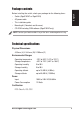
Front panel English Label/LED Color 1 – 24 Indication Identifies the 10/100 port number. STATUS / SPEED Green / Amber Green: Amber: Blinking: Off: 100Mbps 10Mbps Receiving or transmitting data packets There is a problem with the link. DUPLEX / COLLISION Amber On: Switch is operating in full-duplex mode. Blinking: Switch is operating in half-duplex mode and collisions are occurring. Off: Switch is operating in half-duplex mode and no collisions are detected.
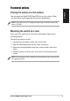
Placement options English Placing the switch on a flat surface You may place the GigaX1024P/GigaX1024 on any flat surface. Make sure the location meets operating environment specifications. NOTE. The length of the UTP Category 5 cable length should not exceed 100 meters (328 feet). Mounting the switch on a rack Each side of the switch has 3 screw holes and two post holes for the mounting bracket. To mount the switch on a rack: 1. Locate three screw holes on both sides of the switch. 2.
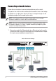
Connecting network devices English Follow these instructions to connect network devices to the switch. The port on the switch can be used to uplink to another switch, hub, bridge or repeater as an uplink port. Either crossover or straight-through can be detected and adjust for the cable by the switch. NOTE: Use Category 5 Ethernet straight-through cables to ensure proper connections between the switch and other network devices.
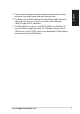
ASUS GigaX1024P/GigaX1024 English 2. Plug one end of the power cable to the power connector on the switch rear panel, then plug the other end to an electrical outlet. 3. The Power LED and LED indicators for active Ethernet ports light up to indicate that the device is on and in use. Refer to the front panel Label/LED table for LED indications. 4 For GigaX1024P only, you can install ASUS CNM in any Windows OS and use CNM to manage the switch. For CNM details, please refer to CNM manual in the CD-ROM.
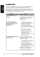
Troubleshooting English This troubleshooting guide provides answers to some common problems which you may encounter while installing and/or using the ASUS GigaX1024 switch. These problems requires simple troubleshooting that you can perform by yourself. Contact the ASUS Technical Support if you encounter problems not mentioned in this section. Problem Action The POWER LED does not light up.
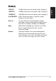
10BASE-T 10 Mbps Ethernet over twisted pair cable (Category 3). 100BASE-T 100 Mbps Ethernet over twisted pair cable (Category 5) 1000BASE-T 1000 Mbps Ethernet over twisted pair cable (Category 5) Auto MDI/MDIX Allows network connections using either straight through or crossover cables. Ethernet The most commonly installed computer network technology, usually using twisted pair wiring. Ethernet data rates are 10 Mbps, 100 Mbps and 1000 Mbps.
English 10 ASUS GigaX1024P/GigaX1024