Centralized Network Management GigaX Smart Switch Management Software User’s Manual E1816 / Oct 2004
Copyright Information No part of this manual, including the products and software described in it, may be reproduced, transmitted, transcribed, stored in a retrieval system, or translated into any language in any form or by any means, except documentation kept by the purchaser for backup purposes, without the express written permission of ASUSTeK COMPUTER INC. (“ASUS”).
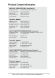
Product Contact Information ASUSTeK COMPUTER INC. (Asia-Pacific) Company Address: 15 Li-Te Road, Peitou, Taipei 112 General Telephone: +886-2-2894-3447 General Fax: +886-2-2894-7798 Web Site Address: www.asus.com.tw General Email: info@asus.com.
Table of Contents Copyright Information 2 Limitation of Liability ................................................................. 2 Product Contact Information 3 1 Introduction 5 1.2 Using this Document ......................................................... 5 2 Getting to Know the GigaX Smart Switch 6 2.1 Parts List ........................................................................... 6 2.2 GigaX Smart Switch Features ........................................... 6 2.3 Technical Specifications ..
1 Introduction Congratulations on your purchase of the ASUS GigaX Smart Switch. You can now manage your LAN (Local Area Network) through a friendly and powerful user interface, the ASUS CNM. The ASUS CNM runs on Windows OS. Please refer to the CNM installation guide for CM installation details. This User Guide will show you how to set up the GigaX Smart Switch through CNM, and how to customize its configuration to get the most out of this product. 1.2 Using this Document 1.2.
2 Getting to Know the GigaX Smart Switch 2.1 Parts List In addition to this document, the switch should come with the following: • • • • • GigaX Smart Switch AC Power cord Rack installation kit (2 brackets with 6 screws (M3 x 6L)) Installation CD-ROM Quick installation guide 2.
2.4 Front Panel The front panel contains LED indicators that show the status of the unit.
3 Quick Start Guide This Quick Start Guide provides basic instructions to set up the GigaX Smart Switch environment. • Part 1 shows you how to install the GigaX Smart Switch on a flat surface or in a rack. • Part 2 provides instructions to set up the hardware. • Part 3 shows you how to configure basic settings on the GigaX Smart Switch. This Quick Start Guide assumes that you have installed ASUS CNM in a Windows PC. Both the switch and the PC are located in the same network.
3.2 Part 2 —Start the Switch In Part 2, this guide will show you how to connect the switch to a power outlet, to your computer (with CNM installed), and to the network. 3.2.1 Step 1. Connect to the PC with CNM Installed The switch can be managed through the ASUS CNM software that is running on a Windows OS computer. Please refer to the CNM installation guide for details. Before starting the CNM application, you have to connect the PC to the same network as the switch is attached to. 3.2.2 Step 2.
LED Indicators This LED POWER STATUS of 10/100 ports STATUS of Gigabit ports (GigaX 1024P only) Should be Solid green to indicate that the device is turned on. If this light is not on, check if the power cord is attached to the switch and if it is plugged into a power source. Solid green/amber to indicate that the device can communicate with your LAN or flashing when the device is sending or receiving data from your LAN computer.
Figure 3.2 CNM Outlook (GigaX 1024P) Figure 3.2.
3. Select the proper NIC at the same network with the switch, then click on the Discovery icon in the tool bar. After the discovery is done, the left frame of the window will show the MAC addresses of the switches discovered by the CNM as shown below. Figure 3.3 Available Switches (GigaX 1024P) Figure 3.3.
4. Select the switch you want to manage by clicking on the MAC address, then you can start to configure the switch by CNM. 5. If the CNM cannot discover the switch you want to manage, please repeat step 1 to 4 again. Note: The switch must be powered on and connect to your network before starting the CNM. 3.3.2 Password Recovery The switch is protected by a password. The password is required to make CNM able to manage the switch.
4 Management Functions ASUS provide a Centralized Network Management (CNM) software to allow users manage the switch in your network. The program is designed to work best with Microsoft Windows operation system. 4.1 Start CNM Program 1. Install CNM in a computer running Windows OS. Refer to CNM installation guide for detail installation steps. 2. The computer with CNM installed must be in the same network as the switches are. 3. Make sure the switches are power on and the network links are good. 4.
4.2 Functional Layout The CNM window consists of three separate frames. The top frame has switch logo and front panel as shown below. This frame remains on the top of the browser window all the times and updates the LED status periodically. The LED definition has been described in Table 3.1. Each port shows different states by different colors, shown as Table 4.1. Figure 4.2. Top frame (GigaX 1024P) Figure 4.2.
The left frame, a topology frame as shown in Figure 4.3, contains all the NICs in the manage station. Each NIC has a tree view to show the switches that are discovered by CNM. You can click on any of these to display a specific configuration of the switch. Figure 4.3 A Topology Frame Click on the NIC, it shows the topology of the switches in the network. If multiple switches are cascaded, the tree view will show the relationship of those switches as Figure 4.4. Figure 4.
4.3 General Settings for CNM There are menu bar and tool bar on the top of the CNM window. They offer general settings for CNM. • The Topology item provides the general network discovery, manually add or delete switches, and load or save the current discovered topology. • The Setup item provides the update interval and password settings. • The Help item provides CNM information and instructions 4.3.1 Topology Figure 4.5 Topology Topology is to control the actions of the topology frame.
5. Add Switch: add a switch to the topology tree manually. A window will show for this purpose as shown below. Select the network adapter you want the switch to attach to, give the switch MAC and name, and an authentication key as the password if you don’t use the default one (2379), then click OK to finish the action. However, a manually added switch does not mean it can be configured or discovered by CNM.
6. Remove Switch: you can remove any switch in the topology list manually through this function. It pops out a switch list and check those switches you want to remove. Please refer to Figure 4.7 for the switch list window. Figure 4.7 Remove Switch 4.3.2 Setup Figure 4.8. Setup CNM polls the switch status periodically, the polling interval can be adjusted. 1. Auto Update Time Interval: as Figure 4.9, a proper value can be set.
4.4 Switch Topology The switch topology frame is on the left part of the CNM window. It shows the discovered switches and the relationship among them. Each presents a NIC interface. The interface name and MAC address is shown after the. The switch topology shows the relationship among the switches in a tree view. That is, if a switch A has connections to switch B and your NIC, then a cascade tree will display as Figure 4.10. Figure 4.
4.4.2 Switch Add and Removal Discovery action will create the topology tree by all the discovered switches. The default password will be used in the discovery process. Sometimes you may have a switch with another password that is different from the default one. In this case, the switch cannot be discovered by the default password. You need to add a switch to the topology manually. As shown below, some fields require data entered to add a switch. Figure 4.11 Add Switch (GigaX 1024P) Figure 4.11.
Once a switch is added to the topology tree, you can find it in the corresponding place. You have to left click the switch symbol to switch the current status/ configuration window from other switch to this switch. If the communication is good, you can see the linking status window on the right frame of the CNM window, and the topology tree will display the switch symbol in a correct place to show the relationship.
4.5 Switch Setup Before using the configuration windows, it is better to know following buttons or icons because they are used throughout the setup. The following table describes the function for each button or icon. Table 4.
4.6 System The system menu provides reboot, link status, and change password. 4.6.1 Reboot Hardware and software reset functions are provided. Hardware reset returns the system to its initial state just like power on hardware reset. Note: Hardware reset will clear all configuration settings. Software reset will return the system to the initial state and start port link negotiations, but the MAC table, VLAN table data, and configuration settings will not be erased. Figure 4.
4.6.2 Link Status Link status table shows the port information including speed, duplex mode and flow control. Click on the Reload button will get the update information. Figure 4.14 shows the status table. Figure 4.14 Link Status (GigaX 1024P) Figure 4.14.
4.6.3 Change Password A valid password consists of 4 digits, from 0 to 9, and a to f. The authenticator does not check upper case or lower case. For example, password “12ab” is treated as “12AB”. Once the password gets changed, CNM will use the password to retrieve the information about the switch. If the password is forgotten, please refer to 3.3.2 to reset the password in the switch. After it, you have to remove the switch from the topology and discover the switch again.
4.6.4 Load You can load configuration from the switch or the local file as shown below. This action will update the current configuration in the CNM. If you want to keep the current configuration, please refer to section 4.6.5. Figure 4.15 Load (GigaX 1024P) Figure 4.15.
4.6.5 Save Save all the configurations to a local file for future reference. Once you create a configuration file in CNM, you can use it to apply to the other switches to save your time. It is also a backup file for configuration. It is recommended to have a good file name to identify that the configuration is for the certain switch(es). Figure 4.16 Save Configuration (GigaX 1024P) Figure 4.16.
4.6.6 Apply and Save It applies all the current settings in CNM to the switch and save them in the switch permanently. It is recommended to back up the existed switch configurations before applying a new configuration to the switch. Figure 4.17 Apply Configuration (GigaX 1024P) Figure 4.17.
4.7 Configuration The Configuration menu provides the configuration for all the functions that the switch can supports, like physical interface, link aggregation, bandwidth control, traffic control, VLAN, IGMP snooping and QoS. To keep all the new configurations and save the bandwidth for communications, each configuration page will not retrieve information from switch until you click the Reload button. In some configuration pages, you can select the ports to reload the information from the switch. 4.7.
Figure 4.18.1 Physical Interface (GigaX 1024I) Above shows the configuration for each port. Select the ports you want to configure or reload information from the switch by clicking on the check boxes in front of the ports, then click on Config to set the configuration for the ports, or click on Reload to retrieve configuration from the switch, or click on Apply to apply the new settings to the switch. Some settings you can do to the physical interface. 1. Enable or disable a port 2. Speed and duplex mode.
4.7.2 Link Aggregation Figure 4.19 Link Aggregation (GigaX 1024P) Figure 4.19.
Link aggregation creates new virtual links with more bandwidth. For example, port 1 and 2 can work together as one link to another device. The new virtual link has 200Mbps bandwidth. The switch provides 8 groups (GigaX 1024P) or 7 groups (GigaX 1024I) of link aggregations shown above. Click on the Reload button to retrieve the configuration from switch. The checked trunk group means this group has been activated.
Figure 4.20.1 Bandwidth Configuration (GigaX 1024I) GigaX Smart Switch provides TX/RX bandwidth control for each port. Please reload the configuration before you start to set up new configuration. The page is shown above. Select the ports you want to configure, then select proper bandwidth for TX/RX directions. Click on Apply to apply to the switch.
4.7.4 Traffic Control Traffic control is to set the following items 1. Broadcast storm filtering control: if enabled, each port start to drop broadcast packets after a continuous received broadcast packets count up to 64. It will be back to normal if no more broadcast packet is received in 800ms or any nonbroadcast packet is received. 2. IP multicast packet flow control: if enabled, the system will drop IP multicast packets under a congestion condition.
Figure 4.21 VLAN (GigaX 1024P) Figure 4.21.
All VLAN behavior will be influenced by VLAN control option. Click Control Option and a window will appear as shown as below. Enable or disable these options carefully, these options are global setting for VLAN Figure 4.22 VLAN Control Options 7. VLAN function: enable or disable the VLAN function. 8. Unicast packet inter-VLAN leaky: to enable the packet to be forwarded to a destination port (L2 table hit) at different VLAN. 9.
4.7.6 IGMP Snooping Enable the IGMP snooping will let the switch learn the multicast router port and group address member ports into the multicast address table. The table is combined with L2 MAC table, so the maximum entry is 8K. The valid port member will auto aging out after about 5 minute idle. See figures below. Figure 4.23 IGMP Snoop (GigaX 1024P) Figure 4.23.
4.7.7 QoS Setup The system support 2 level priority queues. The queue service rate is based on the packet-based Weighted Round Robin algorithm. The ratio can be set as 4:1, 8:1, 16:1, or strictly high priority first. The port-based priority is to decide the packet priority by the receiving ports. You can select the high priority ports from the switch graphic.
Figure 4.24.
4.8 Statistics Statistics offer Port Traffic, Traffic History and Comparison charts. The switch has 3 counters for 8 kinds of statistics. So you cannot see all the statistics at the same time. That is, the old statistics data will be gone if you start to use the counter for another statistics. 4.8.1 Port Traffic Select port number, the statistics item and color to draw the traffic chart. The chart will be auto updated in the time interval you set in Setup menu. Refer to 4.3.2 for time interval setup.
4.8.2 Traffic History Select the statistics item, ports and colors you want to see in the chart, then press the Draw Traffic Chart button to start the drawing. The chart will be auto updated in the time interval you set in Setup menu. Refer to 4.3.2 for time interval setup. Figure 4.26 Traffic History (GigaX 1024P) Figure 4.26.
4.8.3 Comparison Select the statistics item to do comparison for port 1 to 26 (ports 25-26 on GigaX 1024P only). Press the Draw Traffic Chart button to start the drawing. The chart will be auto updated in the time interval you set in Setup menu. Figure 4.27 Port Comparison (GigaX 1024P) Figure 4.27.
GigaX Smart Switch Centralized Network Management