
Owner manual


4
Hardware description
This section introduces the physical features of the GigaX1048 switch and its installation
procedure.
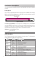
Front panel
The front panel of GigaX1048 switch features forty-eight RJ-45 10/100Mbps ports (auto MDI/
MDIX), one RJ-45 10/100/100Mbps port, one Mini GBIC slot for fiber connection, and LED
indicators that indicate the condition of the switch.
Figure 1. Front panel
RJ-45 Ports (Auto MDI/MDIX):
The forty-eight RJ-45 10/100Mbps ports are auto MDI/MDIX
ready. Auto MDI/MDIX means that you can connect any compatible networking devices (e.g.
workstation, PC, switch, hub, etc.) using either a straight or cross-over Ethernet cable. Some
early models require straight and crossover cable for connecting different devices.
Gigabit port:
1 x 10/100/1000Mbps UTP port
1 x Mini GBIC slot.
Note:
Mini GBIC module is optional.
LED indicators
The LED indicators provide real-time information of operation status. The following table
provides descriptions of LED status and their meaning.
LED Status Description
Power
Green Unit is powered on
Off
No power
LNK/ACT
Green Ethernet link is established
Flashing Data is being transmitted
Off
No Ethernet link
LNK/ACT
(Gigabit
copper,G1)
Green Ethernet link is established
Flashing Data is being transmitted
Off
No Ethernet link
Speed (Gigabit
copper,G1)
Yellow
The port is operating in 1000Mbps mode.
Off
The port is operating in 10/100Mbps mode or no
device is attached.
LNK/ACT (Mini
GBIC, G2)
Green Ethernet link is established
Flashing Data is being transmitted
Off
No data being transmitted
LED Indicators