
User's Manual
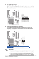

Table Of Contents
- Chapter 1
- Chapter 2
- Chapter 3
- BIOS setup
- 3.1 BIOS setup program
- 3.2 Main menu
- 3.3 Advanced menu
- 3.3.1 PCH-FW Configuration
- 3.3.2 Trusted Computing
- 3.3.3 CPU Configuration
- 3.3.4 Graphics Configuration
- 3.3.5 PCI Express Configuration
- 3.3.6 CSM Configuration
- 3.3.7 Super IO Configuration
- 3.3.8 Serial Console Configuration
- 3.3.9 SATA Configuration
- 3.3.10 USB Configuration
- 3.3.11 Onboard Devices Configuration
- 3.3.12 APM Configuration
- 3.3.13 EzFlash
- 3.3.14 Watchdog Timer
- 3.3.15 Network Stack Configuration
- 3.3.16 Miscellaneous
- 3.4 Hardware Monitor menu
- 3.5 Security menu
- 3.6 Boot menu
- 3.7 Exit menu
- BIOS setup
- Appendix

2-23
Chapter 2: Motherboard information
LPT
PIN 1
LPT_XSTB#
LPT_XPD0
LPT_XPD1
LPT_XPD2
LPT_XPD3
LPT_XPD4
LPT_XPD5
LPT_XPD6
LPT_XPD7
LPT_ACK#
LPT_BUSY
LPT_PE
LPT_SLCT
LPT_XAFD#
LPT_ERROR#
LPT_XINIT#
LPT_XSLIN#
GND
GND
GND
GND
GND
GND
GND
GND
13. LPT header (26-1 pin LPT)
The LPT (Line Printing Terminal) header supports devices such as a printer.
LPT is standardized as IEEE 1284, which is the parallel port interface on IBM
PC-compatible computers.
14. Front Panel Audio header (10-1 pin AAFP)
This header is for a chassis-mounted front panel audio I/O module that
supports HD Audio standard. Connect one end of the front panel audio I/O
module cable to this header.
IMPORTANT!
• We recommend that you connect a high-denition front panel audio module
to this header to avail of the motherboard’s high-denition audio capability.
• If you want to connect a high-denition front panel audio module to this
header, set the HD Audio Controller item in the BIOS setup to [Enabled].
AAFP
PIN 1
A_GND
NC
A_JD_FMIC1
A_JD_HPOUT
A_FMIC1
A_FMIC1
A_HPOUT
A_JD_FRONT
A_HPOUT
Connector type
HEADER 2x5p, K8, 2.54mm pitch