
User’s Manual


H310I-IM-A R2.0
2-2
17.0cm(6.7in)
17.0cm(6.7in)
EATXPWR
DDR4 SO-DIMM_A1* (64bit, 260-pin module)
DDR4 SO-DIMM_B1* (64bit, 260-pin module)
M.2_(SOCKET3)
F_PANEL
SPEAKER
AT_ATX_SEL
BLKT_PWR_SEL
SATA6G_2
LCD_BLKT_PANEL
SATA6G_1
CLRTC
AAFP
ALC
887-VD2
HDMI
DP2
DP1
AUDIO
Super
I/O
LAN2_U31G1_E34
LAN1_U31G1_E12
COM2
COM1
COM1_SEL
COM2_SEL
VCC_PWR_SEL
BATTERY
128Mb
BIOS
LGA1151
U31G1_12
Intel
®
H310
Intel
®
I219V
Intel
®
I211AT
PCIEX16_1
ATX12V
CPU_FAN
DIGI
+VRM
CHA_FAN
USB56
COM6
LPC_DEBUG
COM5
COM4
COM3
LVDS
USB78
PANEL_SW
GPIO_CON
TPM
MSATA_MPCIE
ASM
1074
ASM1480
M.2(WIFI)
2242
2260
2280
2230
14
15
16
13
12
9
10
11
18
19
17
202117
12
23
24
26
25
22
6 7 82 5431
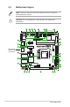
2.2 Motherboard layout
Place this side
towards the rear
of the chassis
NOTE: Place four screws into the holes indicated by circles to secure the
motherboard to the chassis.
CAUTION! Do not overtighten the screws! Doing so can damage the
motherboard.