Industrial Motherboard H610T-EM-A
E23228 Revised Edition V3 January 2024 Copyright © 2024 ASUSTeK COMPUTER INC. All Rights Reserved. No part of this manual, including the products and software described in it, may be reproduced, transmitted, transcribed, stored in a retrieval system, or translated into any language in any form or by any means, except documentation kept by the purchaser for backup purposes, without the express written permission of ASUSTeK COMPUTER INC. (“ASUS”).
Contents Chapter 1 Product overview 1.1 Package contents.......................................................................... 1-1 1.2 Features......................................................................................... 1-1 1.3 Specifications................................................................................ 1-2 Chapter 2 Motherboard information 2.1 Before you proceed...................................................................... 2-1 2.2 Motherboard layout..
3.3.13 EZ-Flash........................................................................ 3-10 3.3.14 Watchdog Timer............................................................. 3-10 3.4 Hardware Monitor menu............................................................. 3-10 3.5 Security menu............................................................................. 3-11 3.6 Boot menu................................................................................... 3-12 3.7 Exit menu.............
Chapter 1 Product overview Chapter 1 Product overview 1.1 Package contents Check your industrial motherboard package for the following items. 1 x ASUS H610T-EM-A Industrial Motherboard 1 x SATA 6.0 Gb/s cable 2 x M.2 screw packages 1 x ASUS I/O Shield NOTE: If any of the above items is damaged or missing, contact your distributor or sales representative immediately. 1.2 Features • LGA1700 socket for Intel® 14th/13th/12th Gen.
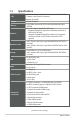
1.3 Specifications CPU LGA1700 socket for Intel® 14th/13th/12th Gen. Core™ i9/ i7/ i5/ i3, Pentium®, and Celeron® Processors Supports up to 65W Chipset Intel® H610 Chipset Memory 2 x SO-DIMM, max.
1 x GPIO header (8-bit) 1 x LCD Panel Monitor Switch header 1 x Panel signal connector Internal I/O connectors 1 x LVDS Panel VCC Power Selection jumper 1 x LVDS Panel Backlight Enable Signal Selection jumper 1 x LVDS Backlight Panel header 1 x Power in Connector 1 x Amplifier 1 x Buzzer Watch dog timer Yes SKU1: Non-TPM Security SKU2: TPM IC onboard Power requirement 12V / 19V DC in Operation Temperature 0~60°C Non-Operation Temperature -40~85°C Relative Humidity 10%~95% (non-coagulation) Wind
1-4 H610T-EM-A
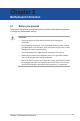
Chapter 2 Motherboard information Chapter 2 Motherboard information 2.1 Before you proceed Take note of the following precautions before you install motherboard components or change any motherboard settings. CAUTION! • Unplug the power cord from the wall socket before touching any component. • Before handling components, use a grounded wrist strap or touch a safely grounded object or a metal object, such as the power supply case, to avoid damaging them due to static electricity.
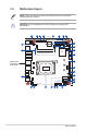
2.2 Motherboard layout NOTE: Place four screws into the holes indicated by circles to secure the motherboard to the chassis. CAUTION! Do not overtighten the screws! Doing so can damage the motherboard. 2 CHA_FAN 3 4 5 17.0cm(6.
Connectors/Jumpers/Slots Page 1. CPU and Chassis Fan connectors (4-pin CPU_FAN, 4-pin CHA_FAN) 2-16 2. COM Debug header (5-1 pin COM_DEBUG) 2-24 3. General Purpose Input/Output header (10-pin GPIO_CON) 2-21 4. SATA 6.0 Gb/s ports (7-pin SATA6G_1-3) 2-21 5. COM RING/+5V/+12V Selection jumpers (6-pin COM1/2/3/4_SEL) 2-12 6. COM Port headers (10-1pin COM1 - COM4) 2-22 7. Chassis Intrusion header (4-1 pin CHASSIS) 2-20 8. AT/ATX mode Selection jumper (3-pin AT_ATX_SEL) 2-12 9.
2.3 Central Processing Unit (CPU) The motherboard comes with a surface mount LGA1700 socket designed for the Intel® 14th/13th/12th Gen. Core™ i9 / Core™ i7 / Core™ i5 / Core™ i3, Pentium®, and Celeron® Processors. LGA1700 IMPORTANT: Unplug all power cables before installing the CPU. CAUTION! 2-4 • Ensure that you install the correct CPU designed for LGA1700 socket only.
2.3.1 Installing the CPU • Ensure that you install the correct CPU designed for LGA1700 socket only. DO NOT install a CPU designed for LGA1155, LGA1156, LGA1151, and LGA1200 sockets on the LGA1700 socket. • ASUS will not cover damages resulting from incorrect CPU installation/ removal, incorrect CPU orientation/placement, or other damages resulting from negligence by the user.
2 3 A B 4 5 B A 2-6 H610T-EM-A
2.3.2 CPU heatsink and fan assembly installation CAUTION! Apply the Thermal Interface Material to the CPU heatsink and CPU before you install the heatsink and fan if necessary.
4 • We recommend using a LGA1700 compatible cooling system on an Intel® 600 series motherboard. • Push-pin type LGA1200 compatible cooling systems cannot be installed to this motherboard.
2.4 System memory This motherboard comes with two Double Data Rate 4 (DDR4) Dual Inline Memory Module (DIMM) sockets. The figure below illustrates the location of the DDR4 DIMM sockets: SO-DIMM_B1 SO-DIMM_A1 Channel Sockets Channel A DIMM_A1 Channel B DIMM_B1 IMPORTANT! • You may install varying memory sizes in Channel A and Channel B. The system maps the total size of the lower-sized channel for the dual-channel configuration.
To install a SO-DIMM 2 3 To remove a SO-DIMM 2 2-10 3 H610T-EM-A
2.5 1. Jumpers Clear CMOS jumper (2-pin CLRTC) The Clear CMOS jumper allows you to clear the Real Time Clock (RTC) RAM in the CMOS, which contains the date, time, system passwords, and system setup parameters. CLRTC GND +3V_BAT PIN 1 Connector type HEADER 1x2p, 2.54mm pitch, S/T To erase the RTC RAM: 1. Turn OFF the computer and unplug the power cord. 2. Short-circuit pin 1-2 with a metal object or jumper cap for about 5-10 seconds. 3. Plug the power cord and turn ON the computer. 4.
2. COM Ring/+5V/+12V Selection jumper (6-pin COM1/2/3/4_SEL) B A D A B C C D 3. COM4_SEL COM3_SEL COM2_SEL COM1_SEL 2 1 4 3 6 5 +12V +5V RI (Default) Setting +12V Pins 1-2 +5V 3-4 Ring (Default) 5-6 AT/ATX mode Selection jumper (3-pin AT_ATX_SEL) AT_ATX_SEL 1 2 ATX mode (Default) Pins 1-2 (Default) ATX mode 2-3 AT mode Connector type 2-12 2 3 AT mode HEADER 1x3p, 2.
4. LVDS Panel Backlight Enable Signal Selection jumper (BKLTEN_SEL) 1 2 2 3 BKLTEN_SEL High Active (Default) BKLTEN_SEL HIGH active Pins 1-2 LOW active 2-3 Connector type 5. Low Active HEADER 1x3p, 2.54mm pitch, S/T LVDS Panel VCC Power Selection jumper (6-pin VCC_PWR_SEL) VCC_PWR_SEL 3 4 2 3V (Default) Setting 12V Pins 5-6 5V 4-3 3V (Default) 1-2 Connector type 5 6 1 5V 12V HEADER 1 x 3p, 2.
2.6 Connectors 2.6.1 Rear panel connectors 1 2 3 4 5 6 1. USB 3.2 Gen 1 (up to 5Gbps) ports. These 9-pin Universal Serial Bus (USB) ports are for USB 3.2 Gen 1 devices. 2. DisplayPort. These ports are for a DisplayPort-compatible devices. 3. LAN (RJ-45) ports. These ports allow Gigabit connection to a Local Area Network (LAN) through a network hub.
To configure a 7.1-channel audio output: Use a chassis with HD audio module in the front panel to support a 7.1-channel audio output. 6. DC power connector. Insert the power adapter into this port. CAUTION! To avoid potential damage or system instability, do not connect both the DC power connector and the ATX Power connector simultaneously.
2.6.2 1. Internal connectors ATX Power connector (4-pin DC_PWR2) Correctly orient the ATX power supply plugs into these connectors and push down firmly until the connectors completely fit. DC_IN DC_IN DC_PWR2 GND GND PIN 1 CAUTION! To avoid potential damage or system instability, do not connect both the DC power connector and the ATX Power connector simultaneously. 2.
3. USB 2.0 headers (10-1 pin USB_56, USB_78) USB+5V USB_P7USB_P7+ GND NC These headers are for USB 2.0 ports. Connect a USB cable to the header. The USB headers comply with USB 2.0 specification that supports up to 480 Mbps connection speed. PIN 2 PIN 10 USB_78 USB+5V USB_P5USB_P5+ GND NC PIN 1 USB+5V USB_P8USB_P8+ GND A A Connector type USB_56 B PIN 1 PIN 10 USB+5V USB_P6USB_P6+ GND PIN 2 B HEADER 2x5p, K9, 2mm pitch CAUTION! Never connect a 1394 cable to the USB header.
GND S_CNV_WT_CLK_P S_CNV_WT_CLK_N GND S_CNV_WT_D0_P S_CNV_WT_D0_N GND S_CNV_WT_D1_P S_CNV_WT_D1_N GND S_WAKE#_WIFI CK_REQ_M2_WLAN#_R GND CK_WIFI_CLKN CK_WIFI_CLKP GND S_WIFI_RXN S_WIFI_RXP GND S_WIFI_TXN_C S_WIFI_TXP_C GND Key Key Key Key S_CNV_WR_CLK_P S_CNV_WR_CLK_N GND S_CNV_WR_D0_P S_CNV_WR_D0_N GND S_CNV_WR_D1_P S_CNV_WR_D1_N GND S_USB_PN14_CN S_USB_PP14_CN GND +3VSB_WIFI +3VSB_WIFI NC NC NC NC NC NC NC S_WIFI_DISABLE_N S_BT_DISABLE_N S_PLTRST# S_SUSCLK_R NC NC NC NC NC NC S_CNV_BRI_DT S_CNV_RGI_RSP S
7. System Panel header (10-1 pin F_PANEL) This header supports several chassis-mounted functions. Connector type GND PWRBTN#_PANEL PLEDPLED+ PIN 2 NC O_RSTCON#_PR GND HDD_LEDHDD_LED+ PIN 1 RESET PIN 9 +HDD_LED- +PWR_LED- PWR_BTN F_PANEL HEADER 2x5p, K10, 2.54mm pitch • System power LED (2-pin +PWR_LED) • This 2-pin header is for the system power LED. Connect the chassis power LED cable to this header.
8. Stereo Speaker header The internal stereo speaker header allows connection to a pair of internal, low-power speakers for basic system sound capability. The subsystem is capable of driving both 4Ω 3W speakers at the same time. SPK_OUT A_SPK_LA_SPK_L+ A_SPK_R+ A_SPK_R- PIN 1 9. Chassis Intrusion header (4-1 pin_CHASSIS) This header is for a chassis-mounted intrusion detection sensor or switch. Connect one end of the chassis intrusion sensor or switch cable to this connector.
10. SATA 6.0Gb/s ports (7-pin SATA6G_1-3) These ports connect to SATA 6.0 Gb/s hard disk drives or an optical drive via SATA 6.0 Gb/s signal cables. SATA6G_3 GND RSATA_RXP RSATA_RXN GND RSATA_TXN RSATA_TXP GND A A B C B C SATA6G_1 SATA6G_2 GND RSATA_RXP RSATA_RXN GND RSATA_TXN RSATA_TXP GND Connector type SATA CON 7P S/T 11.
12. COM Port headers (10-pin COM1 - COM4) These headers are for serial (COM) ports. Connect the serial port cables to these headers, then install the module to a slot opening at the back of the system chassis.
14. Front Panel Audio header (10-1 pin AAFP) A_JD_HPOUT A_GND NC A_JD_FMIC1 This header is for a chassis-mounted front panel audio I/O module that supports HD Audio standard. Connect one end of the front panel audio I/O module cable to this header. PIN 2 PIN 10 PIN 1 PIN 9 A_FMIC1_L A_FMIC1_R A_HPOUT_R A_JD_FRONT A_HPOUT_L AAFP Connector type HEADER 2x5p, K8, 2.
15. COM Debug header (5-1 pin COM_DEBUG) GND GND GND This header allows connection to a COM Debug card. PIN 2 PIN 6 PIN 1 PIN 5 Connector type +3V O_COMDBG_P80 COM_DEBUG HEADER 2x3p, K3, 2.54 mm pitch, S/T NOTE: The COM Debug Card is purchased separately. 16. LCD Panel Monitor Switch header (2-pin PANEL_SW) This 2-pin header is for connecting a monitor switch that can turn on/off the LCD panel display backlight.
17. LVDS Backlight Panel header (5-pin LCD_BLKT_PANEL) This header is for the LCD panel brightness controls. LCD_BLKT_PANEL +5V NC LCD_ENABKLT_CN GND +12V PIN1 Connector type WAFER 6p, 2.0mm pitch 18. LVDS/EDP header (40-pin LVDS_EDP) This header is for an internal LVDS or embedded DisplayPort connection.
19. SPI header (10-1 pin SPI) This header connects to compatible Serial Peripheral Interface (SPI) devices.
Chapter 3 BIOS setup Chapter 3 BIOS setup Scan the QR code to view the BIOS update guide. 3.1 BIOS setup program Use the BIOS Setup program to update the BIOS or configure its parameters. The BIOS screens include navigation keys and brief online help to guide you in using the BIOS Setup program. Entering BIOS Setup at startup To enter BIOS Setup at startup: Press or during the Power-On Self Test (POST). If you do not press or , POST continues with its routines.
3.1.1 BIOS menu screen Menu bar The menu bar on top of the screen has the following main items: Main For changing the basic system configuration Advanced For changing the advanced system settings Hardware Monitor For displaying the system temperature and changing the fan settings Security For configuring the system security settings Boot For changing the system boot configuration. Exit For selecting the save options and default options.
3.3 Advanced menu The Advanced menu items allow you to change the settings for the CPU and other system devices. Be cautious when changing the settings of the Advanced menu items. Incorrect field values can cause the system to malfunction. 3.3.1 PCH-FW Configuration TPM Device Selection This item allows you to select the TPM device. Configuration options: [dTPM] [PTT] 3.3.2 Trusted Computing Security Device Support This item allows you to enable or disable BIOS support for security devices.
3.3.3 CPU Configuration The items in this menu show CPU-related information the BIOS automatically detects. The items shown in the submenu may be different depending on the type of CPU installed. Intel (VMX) Virtualization Technology When set to [Enabled], a VMM can utilize the additional hardware capabilities provided by Vanderpool Technology.
Enhanced C-states [Disabled] Disables enhanced C1 state. [Enabled] Enables enhanced C1 state. Power Limit 1 Override [Disabled] Disables power limit 1. [Enabled] Enables power limit 1. Power Limit 2 Override [Disabled] Disables power limit 2. [Enabled] Enables power limit 2. Power Limit 2 This item allows you to input the value of power limit 2 in milliwatts. If the value is 0, BIOS will program this value as 1.25 times of Processor Base Power (TDP). For 12.50W, enter 12500.
Serial Port 2 Configuration Serial Port Allows you to enable or disable the serial port (COM).Configuration options: [Disabled] [Enabled] Serial Port 3 Configuration Serial Port Allows you to enable or disable the serial port (COM).Configuration options: [Disabled] [Enabled] Serial Port 4 Configuration Serial Port Allows you to enable or disable the serial port (COM).Configuration options: [Disabled] [Enabled] 3.3.
[None] Disables parity check. [Even] Parity bit is 0 if the num of 1’s in the data bits is even. [Odd] Parity bit is 0 if the num of 1’s in the data bits is odd. [Mark] Parity bit is always 1. [Space] Parity bit is always 0. Mark and Space Parity do not allow for error detection. Stop Bits Stop bits indicate the end of a serial data packet. The standard setting is 1 stop bit. Communication with slow devices may require more than 1 stop bit.
[AHCI] Set to [AHCI] when you want the SATA hard disk drives to use the AHCI (Advanced Host Controller Interface). The AHCI allows the onboard storage driver to enable advanced Serial ATA features that increases storage performance on random workloads by allowing the drive to internally optimize the order of commands. SATA6G_1/2/3 Allow you to enable/disable the SATA6G_1/2/3 port. Configuration options: [Disabled] [Enabled] M.2(SOCKET3) Allow you to enable/disable the M.2(SOCKET3) slot.
3.3.10 NVMe Configuration The NVMe Configuration menu displays the NVMe controller and drive information of the devices connected and allows you to configure NVMe device options settings. 3.3.11 Onboard Devices Configuration HD Audio [Enabled] Enables the HD Audio Device. [Disabled] Disables the HD Audio Device. LAN1 I219V [Enabled] Enables the Intel LAN1 controller. [Disabled] Disables the controller. LAN2 RTL8111H [Enabled] Enables the Intel LAN2 controller.
Power On By RTC [Disabled] Disables RTC to generate a wake event. [Single event] Allows you to generate a single wake event. [Daily event] Allows you to generate a daily wake event. [Weekly event] Allows you to generate a weekly wake event. [Monthly event] Allows you to generate a monthly wake event. 3.3.13 EZ-Flash Enter Ez-Flash mode This item allows you to run EzFlash utility. When you press , a confirmation message appears.
Smart Fan Function System Fan Setting Chassis Fan Temperature 1(~4) Allows you to set the value of temperature1(~4). Chassis Fan FD/RPM 1(~4) Allows you to set the value of Fan Duty/PRM 1(~4) when temperature is T1(~4). CPU Fan Setting CPU Fan Temperature 1(~4) Allows you to set the value of temperature1(~4). CPU Fan FD/RPM 1(~4) Allows you to set the value of Fan Duty/PRM 1(~4) when temperature is T1(~4). 3.
Installed. After you set a password, this item shows Installed. To set a user password: 1. 2. 3. Select the User Password item and press . From the Create New Password box, key in a password, then press . Confirm the password when prompted. To change a user password: 1. 2. 3. 4. Select the User Password item and press . From the Enter Current Password box, key in the current password, then press . From the Create New Password box, key in a new password, then press .
enter the BIOS setup. (Delay time = value * 500ms). Configuration options: [0] [12] Boot up NumLock State [On] Set the power-on state of the NumLock to [On]. [Off] Set the power-on state of the NumLock to [Off]. Quiet Boot Allows you to enable or disable the Quiet Boot option. Configuration options: [Disabled] [Enabled] Fast Boot [Enabled] Select to accelerate the boot speed. [Disable Link] Select to go back to normal boot.
Restore Defaults Restore/load default values for all the setup options. Save as User Defaults This option allows you to save the changes you have made so far as user defaults. Restore User Defaults Restore the user defaults with all the setup options.
Appendix Appendix Notices FCC Compliance Information Responsible Party: Asus Computer International Address: 48720 Kato Rd., Fremont, CA 94538, USA Phone / Fax No: (510)739-3777 / (510)608-4555 This device complies with part 15 of the FCC Rules. Operation is subject to the following two conditions: (1) This device may not cause harmful interference, and (2) this device must accept any interference received, including interference that may cause undesired operation.
Compliance Statement of Innovation, Science and Economic Development Canada (ISED) This device complies with Innovation, Science and Economic Development Canada licence exempt RSS standard(s). Operation is subject to the following two conditions: (1) this device may not cause interference, and (2) this device must accept any interference, including interference that may cause undesired operation of the device.
Declaration of compliance for product environmental regulation ASUS follows the green design concept to design and manufacture our products, and makes sure that each stage of the product life cycle of ASUS product is in line with global environmental regulations. In addition, ASUS disclose the relevant information based on regulation requirements. Please refer to http://csr.asus.com/Compliance.
Simplified UKCA Declaration of Conformity English ASUSTeK Computer Inc. hereby declares that this device is in compliance with the essential requirements and other relevant provisions of related UKCA Directives. Full text of UKCA declaration of conformity is available at: www.asus.com/support. Simplified EU Declaration of Conformity English ASUSTeK Computer Inc. hereby declares that this device is in compliance with the essential requirements and other relevant provisions of related Directives.
Service and Support Visit our multi-language website at https://www.asus.com/support/ Manufacturer ASUSTek COMPUTER INC. Address, City 1F., No. 15, Lide Rd., Beitou Dist.