
User Manual

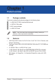

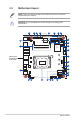
Table Of Contents
- Chapter 1 Product overview
- Chapter 2 Motherboard information
- Chapter 3 BIOS setup
- 3.1 BIOS setup program
- 3.1.1 BIOS menu screen
- 3.2 Main menu
- 3.3 Advanced menu
- 3.3.1 PCH-FW Configuration
- 3.3.2 Trusted Computing
- 3.3.3 CPU Configuration
- 3.3.4 Power Management
- 3.3.5 Super IO Configuration
- 3.3.6 Serial Console Redirection
- 3.3.7 SATA Configuration
- 3.3.8 Network Stack Configuration
- 3.3.9 USB Configuration
- 3.3.10 NVMe Configuration
- 3.3.11 Onboard Devices Configuration
- 3.3.12 APM Configuration
- 3.3.13 EZ-Flash
- 3.3.14 Watchdog Timer
- 3.4 Hardware Monitor menu
- 3.5 Security menu
- 3.6 Boot menu
- 3.7 Exit menu
- 3.1 BIOS setup program
- Appendix

H610T-EM-A
2-2
17.0cm(6.7in)
17.0cm(6.7in)
AAFP
LINE_OUT
MIC_IN
LAN1
LAN2
DC_PWR1
Super
I/O
128Mb
BIOS
BATTERY
F_PANEL
CLRTC
CPU_FAN
SATA_PWRCON
CHA_FAN
DC_PWR2
SPK_OUT
U32G1_12
U32G1_34
DP3
DP2
DP1
COM4_SEL
COM3_SEL COM2_SEL
COM1_SEL
COM_DEBUG
DDR4 So-DIMM_A1 (64bit, 204-pin module)
DDR4 So-DIMM_B1 (64bit, 204-pin module)
LGA1700
SATA6G_1SATA6G_2
SATA6G_3
USB_78 USB_56
RTL
8111H
ALC
897
COM4
BUZZER
COM3 COM2
COM1
SPI
AT_ATX_SELCHASSIS
GPIO_CON
M.2(SOCKET3)
2242
2260
2280
PANEL_SW
M.2(SOCKET3)
LVDS_EDP
PCIE SATA
3.0 X4 V
M.2(WIFI)
LCD_BLKT_PANEL
VCC_PWR SEL
BKLTEN_SEL
VR_PROG
Intel
®
I219V
DIGI+
VRM
Intel
®
H610
14
13
15
4
12
16
17
10
9
11
1
19
18
20
21
22
23
26
25
24
1 2 6 7 843 5
2.2 Motherboard layout
Place this side
towards the rear
of the chassis
NOTE: Place four screws into the holes indicated by circles to secure the
motherboard to the chassis.
CAUTION! Do not overtighten the screws! Doing so can damage the
motherboard.