Motherboard H81T R2.
E9447 First Edition June 2014 Copyright © 2014 ASUSTeK COMPUTER INC. All Rights Reserved. No part of this manual, including the products and software described in it, may be reproduced, transmitted, transcribed, stored in a retrieval system, or translated into any language in any form or by any means, except documentation kept by the purchaser for backup purposes, without the express written permission of ASUSTeK COMPUTER INC. (“ASUS”).
Contents Safety information....................................................................................... iv About this guide.......................................................................................... iv Package contents........................................................................................ vi H81T R2.0 specifications summary........................................................... vi Product introduction 1.1 Before you proceed....................................
Safety information Electrical safety • To prevent electrical shock hazard, disconnect the power cable from the electrical outlet before relocating the system. • When adding or removing devices to or from the system, ensure that the power cables for the devices are unplugged before the signal cables are connected. If possible, disconnect all power cables from the existing system before you add a device.
Where to find more information Refer to the following sources for additional information and for product and software updates. 1. ASUS websites The ASUS website provides updated information on ASUS hardware and software products. Refer to the ASUS contact information. 2. Optional documentation Your product package may include optional documentation, such as warranty flyers, that may have been added by your dealer. These documents are not part of the standard package.
Package contents Check your motherboard package for the following items. Motherboard ASUS H81T R2.0 motherboard Cables 1 x Serial ATA 6.0 Gb/s cable, 1 x Serial ATA 3.0 Gb/s cable, 1 x SATA power cable Accessories 2 x I/O Shield (1 x mini-ITX, 1 x thin mini-ITX) Application DVD Support DVD Documentation User Guide If any of the above items is damaged or missing, contact your retailer. H81T R2.
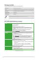
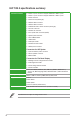
H81T R2.0 specifications summary Storage Intel® H81 Express Chipset: - 1 x Serial ATA 6.0 Gb/s connector - 1 x Serial ATA 3.0 Gb/s connector - 1 x mSATA 6.0 Gb/s connector (full-length)* * mSATA shares the same slot with full length mini PCIe. When mSATA card is inserted, mini PCIe will not be usable. LAN Realtek® 8111G Gigabit LAN controller Audio 4+4 channels Realtek® ALC887-VD High Definition Audio CODEC - Supports Jack-Detection, Anti-pop Function, Front Panel Retasking USB 7 x USB 2.
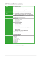
H81T R2.0 specifications summary Internal connectors 2 x USB 2.0 2-port connectors support additional 4 USB 2.0 ports 1 x USB 2.0 1-port connectors support additional 1 USB 2.0 ports 1 x LVDS connector 1 x mini PCIe slot (half-length) 1 x SATA 6.0Gb/s connector 1 x SATA 3.
Product introduction 1.1 Before you proceed 1 Take note of the following precautions before you install motherboard components or change any motherboard settings. 1.2 • Unplug the power cord from the wall socket before touching any component. • Before handling components, use a grounded wrist strap or touch a safely grounded object or a metal object, such as the power supply case, to avoid damaging them due to static electricity. • Hold components by the edges to avoid touching the ICs on them.
1.2.2 Screw holes Place four screws into the holes indicated by circles to secure the motherboard to the chassis. Do not overtighten the screws! Doing so can damage the motherboard. H81T R2.0 Place this side towards the rear of the chassis 1.2.
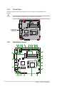
1.2.4 Layout contents Connectors/Jumpers/Slots/LED 1. ATX power connector (2-pin ATX19V) 2. 3. 4. 5. 6. 7. 8. 9. 10. 11. 12. 13. 14. 15. 16. 17. 18. 19. 20. 21. 22. 23. 1.3 CPU and chassis fan connectors (4-pin CPU_FAN, 4-pin CHA_FAN) USB 2.0 connectors (5-1 pin USB11, 10-1 pin USB910, 10-2 pin USB56) Intel® H81 Serial ATA 6.0Gb/s connector (7-pin SATA6G_1 [yellow]) Intel® H81 Serial ATA 3.
Unplug all power cables before installing the CPU. 1.3.1 • Upon purchase of the motherboard, ensure that the PnP cap is on the socket and the socket contacts are not bent. Contact your retailer immediately if the PnP cap is missing, or if you see any damage to the PnP cap/socket contacts/motherboard components. ASUS will shoulder the cost of repair only if the damage is shipment/ transit-related. • Keep the cap after installing the motherboard.
4 5 C A B 1.3.2 CPU heatsink and fan assembly installation Apply the Thermal Interface Material to the CPU heatsink and CPU before you install the heatsink and fan if necessary. ASUS H81T R2.
To install the CPU heatsink and fan assembly 1 2 A B B A 3 4 To uninstall the CPU heatsink and fan assembly 1 2 A B B A 1-6 Chapter 1: Product introduction
1.4 System memory 1.4.1 Overview This motherboard comes with two Double Data Rate 3 (DDR3) Small Outline Dual Inline Memory Module (SO-DIMM) sockets. The figure illustrates the location of the DDR3 SODIMM sockets: H81T R2.0 DIMM_A1 DIMM_B1 Channel Channel A Channel B Sockets DIMM_A1 DIMM_B1 H81T R2.0 204-pin DDR3 DIMM sockets 1.4.2 Memory configurations You may install 1GB, 2GB, 4GB, and 8GB unbuffered non-ECC DDR3 DIMMs into the DIMM sockets.
1.4.3 • The default memory operation frequency is dependent on its Serial Presence Detect (SPD), which is the standard way of accessing information from a memory module. Under the default state, some memory modules for overclocking may operate at a lower frequency than the vendor-marked value. To operate at the vendor-marked or at a higher frequency, refer to section 2.5 Ai Tweaker menu for manual memory frequency adjustment.
1.5 Expansion slots In the future, you may need to install expansion cards. The following sub‑sections describe the slots and the expansion cards that they support. Unplug the power cord before adding or removing expansion cards. Failure to do so may cause you physical injury and damage motherboard components. 1.5.1 Installing an expansion card To install an expansion card: 1.
1.6 Jumpers Clear RTC RAM (2-pin CLRTC) This header allows you to clear the Real Time Clock (RTC) RAM in CMOS. You can clear the CMOS memory of date, time, and system setup parameters by erasing the CMOS RTC RAM data. The onboard button cell battery powers the RAM data in CMOS, which include system setup information such as system passwords. H81T R2.0 +3V_BAT GND CLRTC PIN 1 H81T R2.0 Clear RTC RAM To erase the RTC RAM: 2. 1. Turn OFF the computer and unplug the power cord. 2.
3. Chassis intrusion connector (4-1 pin CHASSIS) This connector is for a chassis-mounted intrusion detection sensor or switch. Connect one end of the chassis intrusion sensor or switch cable to this connector. The chassis intrusion sensor or switch sends a high-level signal to this connector when a chassis component is removed or replaced. The signal is then generated as a chassis intrusion event. By default, the pins labeled “Intruder” are shorted with a jumper cap.
1.7 Connectors 1.7.1 Rear panel connectors 1 2 3 4 5 6 7 9 8 1. DC power connector. Insert the power adapter into this port. 2. USB 3.0 ports 1 and 2. These two 9-pin Universal Serial Bus (USB) ports are for connecting USB 3.0 devices. 3. DVI-I port. This port is for any DVI-I compatible device and are HDCP compliant, allowing playback of HD DVD, Blu-Ray and other protected content. 4. HDMI port.
1.7.2 1. Internal connectors Serial port connector (10-1 pin COM) This connector is for a serial (COM) port. Connect the serial port module cable to this connector, then install the module to a slot opening at the back of the system chassis. PIN 1 DCD TXD GND RTS RI RXD DTR DSR CTS COM H81T R2.0 H81T R2.0 Serial port connector The COM module is purchased separately. 2.
3. Intel® H81 Serial ATA 3.0Gb/s connector (7-pin SATA3G_1) This connector connects to Serial ATA 3.0 Gb/s hard disk drives via Serial ATA 3.0 Gb/s signal cables. GND RSATA_RXP1 RSATA_RXN1 GND RSATA_TXN1 RSATA_TXP1 GND SATA3G_1 H81T R2.0 H81T R2.0 SATA 3.0Gb/s connector When using hot-plug and NCQ, set the SATA Mode Selection item in the BIOS to [AHCI]. 4. Intel® H81 Serial ATA 6.0 Gb/s connectors (7-pin SATA6G_1) These connectors connect to Serial ATA 6.0 Gb/s hard disk drives via Serial ATA 6.
5. Front panel audio connector (10-1 pin AAFP) This connector is for a chassis-mounted front panel HD audio I/O module. Connect one end of the front panel audio I/O module cable to this connector. AAFP PORT2 L SENSE_SEND PORT2 R PORT1 R PORT1 L SENSE2_RETUR H81T R2.0 SENSE1_RETUR NC AGND PIN 1 HD-audio-compliant pin definition We recommend that you panel connect a high-definition front panel audio module to this H81T R2.
8. TPM connector (20-1 pin TPM) This connector supports a Trusted Platform Module (TPM) system, which can securely store keys, digital certificates, passwords, and data. A TPM system also helps enhance network security, protects digital identities, and ensures platform integrity. PWROWN LAD2 LAD1 GND SMBSDA SERIRQ GPIO RESET GND TPM PIN 1 PCICLK FRAME PCIRST# LAD3 +3V LAD0 SMBSCL +3VSB GND SB_SUS_STAT H81T R2.0 H81T R2.0 TPM Connector The TPM module is purchased separately. 9. USB 2.
10. System panel connector (10-1 pin PANEL) This connector supports several chassis-mounted functions. F_PANEL PWR_LED+ PWR_LEDPWR GND +PWR LED PWR BTN H81T R2.0 HDD_LED+ HDD_LEDGround HWRST# (NC) PIN 1 +HDD_LED RESET H81T R2.0 System panel connector • System power LED (2-pin PWR_LED) This 2-pin connector is for the system power LED. Connect the chassis power LED cable to this connector. The system power LED lights up when you turn on the system power, and blinks when the system is in sleep mode.
11. RTC Battery header (2-pin BATT_CON) This connector is for the lithium CMOS battery. VBAT GND BATT_CON H81T R2.0 PIN 1 H81T R2.0 RTC battery header 12. LVDS connector (40-pin LVDS) This connector is for an LCD monitor that supports Low-voltage Differential Signaling (LVDS) interface. H81T R2.0 LVDS PIN 1 H81T R2.0 LVDS connector 13. Flat panel display brightness (8-pin LCD_BLKT_PANEL) This connector is for the LCD panel brightness controls. LCD_BLKT_PANEL H81T R2.
15. Internal stereo speaker header (2-pin SPK_OUT) The internal mono speaker header allows connection to an internal, low-power speaker for basic system sound capability. The subsystem is capable of driving a speaker load of 4 Ohms at 3 Watts (rms). Front_RFront_R+ Front_L+ Front_L- SPK_OUT H81T R2.0 PIN 1 H81T R2.0 Internal Stereo Speakers Header 10.
1.9 Software support 1.9.1 Installing an operating system This motherboard supports Windows® 7 (32/64bit), Windows® 8 (32/64bit) and Windows® 8.1 (32/64bit) Operating Systems (OS). Always install the latest OS version and corresponding updates to maximize the features of your hardware. Motherboard settings and hardware options vary. Refer to your OS documentation for detailed information. 1.9.
BIOS information 2.1 Managing and updating your BIOS 2 Save a copy of the original motherboard BIOS file to a USB flash disk in case you need to restore the BIOS in the future. Copy the original motherboard BIOS using the ASUS Update utility. 2.1.1 EZ Update EZ Update is a utility that allows you to automatically update your motherboard’s softwares, drivers and the BIOS version easily. With this utlity, you can also manually update the saved BIOS and select a boot logo when the system goes into POST.
2.1.2 ASUS EZ Flash 2 The ASUS EZ Flash 2 feature allows you to update the BIOS without using an OS‑based utility. Before you start using this utility, download the latest BIOS file from the ASUS website at www.asus.com. To update the BIOS using EZ Flash 2: 1. Insert the USB flash disk that contains the latest BIOS file to the USB port. 2. Enter the Advanced Mode of the BIOS setup program. Go to the Tool menu to select ASUS EZ Flash Utility and press to enable it. 3.
Recovering the BIOS To recover the BIOS: 1. Turn on the system. 2. Insert the support DVD to the optical drive or the USB flash drive that contains the BIOS file to the USB port. 3. The utility automatically checks the devices for the BIOS file. When found, the utility reads the BIOS file and enters ASUS EZ Flash 2 utility automatically. 4. The system requires you to enter BIOS Setup to recover BIOS settings.
Booting the system to a DOS environment 1. Insert the DOS-bootable USB flash drive with the latest BIOS file and BIOS Updater to your computer’s USB port. 2. Boot your computer. When the ASUS Logo appears, press to show the BIOS Boot Device Select Menu. 3. Select the optical drive as the boot device. The DOS screen appears. Updating the BIOS file To update the BIOS file using BIOS Updater: 1. At the FreeDOS prompt, type bupdater /pc /g and press . 2.
3. Press to switch between screen fields and use the keys to select the BIOS file and press . BIOS Updater checks the selected BIOS file and prompts you to confirm BIOS update. 4. Select Yes and press . When BIOS update is done, press to exit BIOS Updater. Restart your computer. DO NOT shut down or reset the system while updating the BIOS to prevent system boot failure! 2.2 • For BIOS Updater version 1.
• The BIOS setup screens shown in this section are for reference purposes only, and may not exactly match what you see on your screen. • Visit the ASUS website at www.asus.com to download the latest BIOS file for this motherboard. • Ensure that a USB mouse is connected to your motherboard if you want to use the mouse to control the BIOS setup program. • If the system becomes unstable after changing any BIOS setting, load the default settings to ensure system compatibility and stability.
Displays the CPU/motherboard temperature, CPU voltage output, and CPU/chassis fan speed Selects the Advanced mode functions Selects the boot device priority Power saving mode Selects the display language of the BIOS setup program Normal mode Displays the Advanced mode menus ASUS Optimal mode Displays SATA Information Exits the BIOS setup program without saving the changes, saves the changes and resets the system, or enters the Advanced Mode Loads optimized default Displays the system properties of t
Back button Menu items Menu bar Configuration fields Pop-up window Submenu item General help Navigation keys Last modified settings Quick note Scroll bar Menu bar The menu bar on top of the screen has the following main items: My Favorites For saving the frequently-used system settings and configuration Main For changing the basic system configuration Ai Tweaker For changing the overclocking settings Advanced Boot For changing the advanced system settings For displaying the system temperature,
Pop-up window Select a menu item and press to display a pop-up window with the configuration options for that item. Scroll bar A scroll bar appears on the right side of a menu screen when there are items that do not fit on the screen. Press the Up/Down arrow keys or / keys to display the other items on the screen. Navigation keys At the bottom right corner of the menu screen are the navigation keys for the BIOS setup program.
Adding items to My Favorites To add frequently-used BIOS items to My Favorites: 1. Use the arrow keys to select an item that you want to add. When using a mouse, hover the pointer to the item. 2. Press on your keyboard or right-click on your mouse to add the item to My Favorites page. You cannot add the following items to My Favorites: 2.
• If you have forgotten your BIOS password, erase the CMOS Real Time Clock (RTC) RAM to clear the BIOS password. See section 1.6 Jumpers for information on how to erase the RTC RAM. • The Administrator or User Password items on top of the screen show the default Not Installed. After you set a password, these items show Installed. Administrator Password If you have set an administrator password, we recommend that you enter the administrator password for accessing the system.
To clear the user password, follow the same steps as in changing a user password, but press when prompted to create/confirm the password. After you clear the password, the User Password item on top of the screen shows Not Installed. 2.5 Ai Tweaker menu The Ai Tweaker menu items allow you to configure overclocking-related items. Be cautious when changing the settings of the Ai Tweaker menu items. Incorrect field values can cause the system to malfunction.
Target CPU Graphics Speed : xxxxMHz Displays the target iGPU speed. 2.5.1 CPU Core Ratio [Auto] Allows you to set the CPU core ratio automatically or manually. [Auto] Sets all CPU Core Ratio to Intel® CPU default settings automatically. [Sync All Cores] Allows you to set CPU Core Ratio settings for all cores. [Per Core] Allows you to set CPU Core Ratio individually. The following two items appear only when you set the CPU Core Ratio to [Sync All Cores] or [Per Core].
2.5.6 Max. CPU Graphics Ratio [Auto] Allows you to set the CPU Graphics maximum ratio. The maximum ratio is 60x. Use <+>/<-> to adjust the value. 2.5.7 GPU Boost [As is] Allows you to enable the GPU Boost to accelerate the integrated GPU for extreme graphics performance. Configuration options: [As is] [Enabled]. 2.5.8 EPU Power Saving Mode [Auto] Allows you to enable or disable the EPU power saving function. Configuration options: [Auto] [Disabled] [Enabled] 2.5.
DRAM READ to PRE Time [Auto] Configuration options: [Auto] [1 DRAM Clock] – [15 DRAM Clock] DRAM FOUR ACT WIN Time [Auto] Configuration options: [Auto] [1 DRAM Clock] – [255 DRAM Clock] DRAM WRITE to READ Delay [Auto] Configuration options: [Auto] [1 DRAM Clock] – [15 DRAM Clock] DRAM CKE Minimum pulse width [Auto] Configuration options: [Auto] [1 DRAM Clock] – [15 DRAM Clock] DRAM CAS# Write to Latency [Auto] Configuration options: [Auto] [1 DRAM Clock] – [31 DRAM Clock] RTL IOL control DRAM RTL initial V
Dec_WRD [Auto] Configuration options: [Auto] [0] [1] tRDWR [Auto] Configuration options: [Auto] [1 DRAM Clock] – [31 DRAM Clock] tRDWR_dr [Auto] Configuration options: [Auto] [1 DRAM Clock] – [31 DRAM Clock] tRDWR_dd [Auto] Configuration options: [Auto] [1 DRAM Clock] – [31 DRAM Clock] MISC MRC Fast Boot [Enabled] Allows you to enable or disable the MRC fast boot. [Enabled] Enables the MRC fast boot. [Disable] Disables the MRC fast boot.
Turbo Mode [Enabled] Allows you to enable your core processor’s speed to run faster than the marked frequency in a specific condition. Configuration options: [Disabled] [Enabled] • Turbo Mode is only available on selected CPU models only. • The following first three items appear only when you set the Turbo Mode to [Enabled]. Turbo Mode Parameters Long Duration Package Power Limit [Auto] Allows you to limit the turbo ratio’s long duration package power. Use the <+> and <-> keys to adjust the value.
Power Current Slope [Auto] Allows you to set the power current slope. Configuration options: [Auto] [Level 4] [Level 3] [Level 2] [Level 1] [Level 0] ]Level -1] [Level -2] [Level -3] [Level -4]. Power Current Offset [Auto] Allows you to set the power current offset. Configuration options: [Auto] [100%] [87.5%] [75%] [62.5%] [50%] [37.5%] [25%] [12.5%] [0%] [-12.5%] [-25%] [-37.5%] [-50.0%] [-62.5%] [-75%] [-87.5%] [-100%] Power Fast Ramp Response [Auto] Allows you to set the power fast ramp response.
2.5.12 CPU Cache Voltage [Auto] This item allows you to set the CPU Cache voltage. Increase the cache voltage when increasing the ring frequency. Configuration options: [Auto] [Manual Mode] [Offset Mode] CPU Cache Voltage Override [Auto] This item appears only when you set the CPU Cache Voltage to [Manual Mode] and allows you to set the CPU Cache voltage override. The values range from 0.001V to 1.920V with a 0.001V interval.
2.5.14 CPU System Agent Voltage Offset Mode Sign [+] This item allows you to set the CPU system agent voltage offset mode sign. Configuration options: [+] [-]. CPU System Agent Voltage Offset [Auto] This item allows you to set the CPU system agent voltage offset. Increase the value when increasing DRAM frequency. The values range from 0.001V to 0.999V with a 0.001V interval. 2.5.15 CPU Analog I/O Voltage Offset Mode Sign [+] This item allows you to set the CPU analog I/O voltage offset mode sign.
2.5.22 DRAM DATA REF Voltage on CHB [Auto] Allows you to set the DRAM DATA REF Voltage on CHB. The values range from 0.3950V to 0.6300V with a 0.0050V interval 2.6 Advanced menu The Advanced menu items allow you to change the settings for the CPU and other system devices. Be cautious when changing the settings of the Advanced menu items. Incorrect field values can cause the system to malfunction. 2.6.
Active Processor Cores [All] Allows you to choose the number of CPU cores to activate in each processor package. Configuration options: [All] [1] [2] [3] Limit CPUID Maximum [Disabled] [Enabled] Allows legacy operating systems to boot even without support for CPUs with extended CPUID functions. [Disabled] Disables this function. Execute Disable Bit [Enabled] [Enabled] Enables the No-Execution Page Protection Technology. [Disabled] Forces the XD feature flag to always return to zero (0).
CPU C states [Auto] [Auto] Automatic configuration. [Enabled] Enables the CPU C states. [Disabled] Disables the CPU C states. The following items appear only when you set the CPU C states to [Enabled]. Enhanced C1 state [Enabled] [Enabled] Enables enhanced C1 state. [Disabled] Disables enhanced C1 state. CPU C3 Report [Enabled] Allows you to disable or enable the CPU C3 report to OS.
Intel® Rapid Start Technology Intel® Rapid Start Technology [Disabled] Allows you to enable or disable Intel® Rapid Start Technology. Configuration options: [Enabled] [Disabled] The following items appear only when you set the Intel® Rapid Start Technology to [Enabled]. Entry on S3 RTC Wake [Enabled] The system automatically wakes up and set to Rapid Start Technology S4 mode. Configuration options: [Enabled] [Disabled Entry After [x] Allows you to set the wake-up time.
Aggressive LPM Support [Auto] This item appears only when you set SATA Mode Selection to [AHCI] and allows you to enable or disable PCH entering link power state aggressively. Configuration options: [Auto] [Disabled] [Enabled] S.M.A.R.T. Status Check [Enabled] S.M.A.R.T. (Self-Monitoring, Analysis and Reporting Technology) is a monitor system. When read/write of your hard disk errors occur, this feature allows the hard disk to report warning messages during the POST.
LVDS Configuration All-in-One Chassis [None] Select All-in-One Chassis if applicable. EDID Data Source [Pre-Defined] Configuration options: [Pre-Defined] [Flat Panel Display] The following item appears only when you set the EDID Data Source to [Pre-Defined]. Pre-Defined LVDS Panel Type [1920x1080 LVDS] Select LVDS Panel Type. Configuration options: [640x480 LVDS] ~ [2048x1536 LVDS] Screen Brightness [Neutral] Adjust screen brightness.
LVDS Spread Spectrum Control [+/- 0.5% Center Spread] Adjusts LVDS spread spectrum clocking. Configuration options: [Disabled] [+/- 0.5% Center Spread] [+/- 1% Center Spread] DMI Configuration Allows you to control various DMI functions. DMI Gen 2 [Auto] Allows you to enable or disable DMI Gen 2. Configuration options: [Auto] [Enabled] [Disabled] DMI Link ASPM Control [Auto] Allows you to enable or disable the control of Active State Power Management on SA side of the DMI Link.
USB Single Port Control USB3_1~2 [Enabled] Allows you to enable or disable an individual USB port. Refer to the section 1.2.3 Motherboard layout in this user manual for the locations of the USB ports. Configuration options: [Enabled] [Disabled]. USB 3~10, USBE1 [Enabled] Allows you to enable or disable an individual USB port. Refer to the section 1.2.3 Motherboard layout in this user manual for the locations of the USB ports. Configuration options: [Enabled] [Disabled]. 2.6.
Change Settings [IO=3F8h; IRQ=4] This item appears only when you set the Serial Port to [Enabled] and allows you to select the Serial Port base address. Configuration options: [IO=3F8h; IRQ=4] [IO=2F8h; IRQ=3] [IO=3E8h; IRQ=4] [IO=2E8h; IRQ=3] 2.6.9 APM ErP Ready [Disabled] Allows you to switch off some power at S4+S5 or S5 to get the system ready for ErP requirement. When set to [Enabled], all other PME options will be switched off.
2.7 Monitor menu The Monitor menu displays the system temperature/power status, and allows you to change the fan settings. Scroll down to display the other items. 2.7.1 CPU Temperature [xxxOC/xxxOF] The onboard hardware monitor automatically detects and displays the CPU temperature. Select Ignore if you do not wish to display the detected temperature. 2.7.
2.7.4 CPU Q-Fan Control [Enabled] [Disabled] Disables the CPU Q-Fan control feature. [Enabled] Enables the CPU Q-Fan control feature. CPU Fan Speed Low Limit [200 RPM] This item appears only when you enable the CPU Q-Fan Control feature and allows you to disable or set the CPU fan warning speed.
Chassis Fan Profile [Standard] This item appears only when you enable the Chassis Q-Fan Control feature and allows you to set the appropriate performance level of the chassis fan. [Standard] Sets to [Standard] to make the chassis fan automatically adjust depending on the chassis temperature. [Silent] Sets to [Silent] to minimize the fan speed for quiet chassis fan operation. [Turbo] Sets to [Turbo] to achieve maximum chassis fan speed.
2.8 Boot menu The Boot menu items allow you to change the system boot options. Scroll down to display the other items. 2.8.1 Fast Boot [Enabled] [Enabled] Select to accelerate the boot speed. [Disabled] Select to go back to normal boot. The following four items appear when you set Fast Boot to [Enabled]. SATA Support [All Devices] [All Devices] All devices connected to SATA ports will be available during POST. This process will extend the POST time.
Network Stack Driver Support [Disabled] [Disabled] Select to skip the network stack driver from loading during POST. [Enabled] Select to load the network stack driver during POST. Next Boot after AC Power Loss [Normal Boot] [Normal Boot] Returns to normal boot on the next boot after AC power loss. [Fast Boot] Accelerates the boot speed on the next boot after AC power loss. 2.8.2 Boot Logo Display [Enabled] [Auto] Adjusts logo automatically based on Windows® display requremenst.
2.8.7 Setup Mode [EZ Mode] [Advanced Mode] Sets Advanced Mode as the default screen for entering the BIOS setup program. [EZ Mode] 2.8.8 Sets EZ Mode as the default screen for entering the BIOS setup program. CSM (Compatibility Support Module) Allows you to configure the CSM (Compatibility Support Module) items to fully support the various VGA, bootable devices and add-on devices for better compatibility.
OS Type [Windows UE...] Allows you to select your installed operating system. [Windows UEFI mode] Executes the Microsoft® Secure Boot check. Only select this option when booting on Windows® UEFI mode or other Microsoft® Secure Boot compliant OS. [Other OS] Get the optimized function when booting on Windows® non-UEFI mode, Windows® Vista/XP, or other Microsoft® Secure Boot non-compliant OS. Only on Windows® UEFI mode that Microsoft® Secure Boot can function properly.
Key-exchange Key (KEK) refers to Microsoft® Secure Boot Key-Enrollment Key (KEK). Delete the KEK Allows you to delete the KEK from your system. Configuration options: [Yes] [No] Load KEK from File Allows you to load the downloaded KEK from a USB storage device. Append KEK from file Allows you to load the additional KEK from a storage device for an additional db and dbx loaded management. The KEK file must be formatted as a UEFI variable structure with time-based authenticated variable.
2.8.10 Boot Option Priorities These items specify the boot device priority sequence from the available devices. The number of device items that appears on the screen depends on the number of devices installed in the system. • • 2.8.11 To select the boot device during system startup, press when ASUS Logo appears. To access Windows OS in Safe Mode, do any of the following: • Press when ASUS Logo appears. • Press after POST. Boot Override These items displays the available devices.
Save to Profile Allows you to save the current BIOS settings to the BIOS Flash, and create a profile. Key in a profile number from one to eight, press , and then select Yes. Load from Profile Allows you to load the previous BIOS settings saved in the BIOS Flash. Key in the profile number that saved your CMOS settings, press , and then select Yes.
Save Changes & Reset Once you are finished making your selections, choose this option from the Exit menu to ensure the values you selected are saved. When you select this option or if you press , a confirmation window appears. Select Yes to save changes and exit. Discard Changes & Exit This option allows you to exit the Setup program without saving your changes. When you select this option or if you press , a confirmation window appears. Select Yes to discard changes and exit.
Appendices Notices Federal Communications Commission Statement This device complies with Part 15 of the FCC Rules. Operation is subject to the following two conditions: • This device may not cause harmful interference. • This device must accept any interference received including interference that may cause undesired operation. This equipment has been tested and found to comply with the limits for a Class B digital device, pursuant to Part 15 of the FCC Rules.
Canadian Department of Communications Statement This digital apparatus does not exceed the Class B limits for radio noise emissions from digital apparatus set out in the Radio Interference Regulations of the Canadian Department of Communications. This class B digital apparatus complies with Canadian ICES-003.
ASUS contact information ASUSTeK COMPUTER INC. Address 15 Li-Te Road, Peitou, Taipei, Taiwan 11259 Telephone +886-2-2894-3447 Fax +886-2-2890-7798 E-mail info@asus.com.tw Web site http://www.asus.com Technical Support Telephone Fax Online support +86-21-3842-9911 +86-21-5866-8722 ext. 9101# http://support.asus.com/techserv/techserv.
A-4 Appendices (510)739-3777/(510)608-4555 800 Corporate Way, Fremont, CA 94539. Asus Computer International Date : Signature : Representative Person’s Name : Jun. 16, 2014 Steve Chang / President This device complies with part 15 of the FCC Rules. Operation is subject to the following two conditions: (1) This device may not cause harmful interference, and (2) this device must accept any interference received, including interference that may cause undesired operation.