
User Manual

ASUS H81T R2.0
1-17
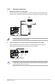
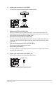
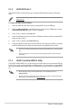
10. System panel connector (10-1 pin PANEL)
Thisconnectorsupportsseveralchassis-mountedfunctions.
• SystempowerLED(2-pinPWR_LED)
This2-pinconnectorisforthesystempowerLED.ConnectthechassispowerLED
cabletothisconnector.ThesystempowerLEDlightsupwhenyouturnonthesystem
power,andblinkswhenthesystemisinsleepmode.
• HarddiskdriveactivityLED(2-pinHDD_LED)
This2-pinconnectorisfortheHDDActivityLED.ConnecttheHDDActivityLEDcable
tothisconnector.TheHDDLEDlightsuporasheswhendataisreadfromorwritten
totheHDD.
• ATXpowerbutton/soft-offbutton(2-pinPWR_BTN)
This connector is for the system power button.
• Resetbutton(2-pinRESET)
This 2-pin connector is for the chassis-mounted reset button for system reboot without
turning off the system power.
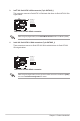
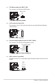
11. Display panel power button (2 pin PANEL_SW)
This connector is used for the display panel power switch.
H81T R2.0
H81T R2.0 System panel connector
PIN 1
PWR BTN
PWR_LED+
PWR_LED-
PWR
GND
HDD_LED+
HDD_LED-
Ground
HWRST#
(NC)
F_PANEL
+PWR LED
+HDD_LED RESET
H81T R2.0
H81T R2.0 Display panel power button
PIN 1
MON_SW#
GND
PANEL_SW