Motherboard H97-PRO GAMER
J9495 改訂版 第2刷 2016年8月 Copyright © 2014 ASUSTeK COMPUTER INC. All Rights Reserved. バックアップの目的で利用する場合を除き、本書に記載されているハードウェア・ソフトウェアを含む、全ての内 容は、ASUSTeK Computer Inc.
もくじ 安全上のご注意.................................................................................................................iv このマニュアルについて......................................................................................................v パッケージの内容..............................................................................................................vi H97-PRO GAMER 仕様一覧..............................................................................................vi Chapter1 製品の概要 1.1 マザーボードの概要..
安全上のご注意 電気の取り扱い ・ 本製品、周辺機器、ケーブルなどの取り付けや取り外しを行う際は、必ずコンピューターと周 辺機器の電源ケーブルをコンセントから抜いて行なってください。お客様の取り付け方法に 問題があった場合の故障や破損に関して弊社は一切の責任を負いません。 ・ 電源延長コードや特殊なアダプターを用いる場合は専門家に相談してください。これらは、 回路のショート等の原因になる場合があります。 ・ ご使用の電源装置に電圧選択スイッチが付いている場合は、システムの損傷を防ぐために 電源装置の電圧選択スイッチがご利用の地域の電圧と合致しているかをご確認ください。ご 利用になる地域の電圧が不明な場合は、各地域の電力会社にお問い合わせください。 ・ 電源装置が故障した場合はご自分で修理・分解をせず、各メーカーや販売店にご相談ください。 ・ 光デジタルS/PDIFは、光デジタルコンポーネントで、クラス1レーザー製品に分類されてい ます。 (本機能の搭載・非搭載は製品仕様によって異なります) 不可視レーザー光です。ビームを直接見たり触れたりしないでください。 操作上の注意 ・ 作業を行う前
このマニュアルについて このマニュアルには、マザーボードの取り付けや構築の際に必要な情報が記してあります。 マニュアルの概要 本章は以下のChapter から構成されています。 • Chapter 1: 製品の概要 マザーボードの機能や各部位についての説明、及びコンポーネントの取り付けに必要なハ ードウェアのセットアップ手順。 • Chapter 2: UEFI BIOS設定 UEFI BIOS Utilityでのシステム設定の変更方法とパラメータの詳細。 • Chapter 3: 付録 製品の規格や海外の法令について。 詳細情報 1. ASUSオフィシャルサイト(http://www.asus.com/) 多言語に対応した弊社ウェブページで、製品のアップデート情報やサポート情報をご確認 いただけます。 2.
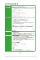
パッケージの内容 製品パッケージに以下のものが揃っていることを確認してください。 マザーボード H97-PRO GAMER ケーブル SATA 6Gb/sケーブル×4 アクセサリー I/Oシールド ×1 ディスク サポートDVD ドキュメント ユーザーマニュアル 万一、付属品が足りない場合や破損していた場合は、すぐにご購入元にお申し出ください。 H97-PRO GAMER 仕様一覧 対応CPU LGA1150ソケット: 4th / New 4th / 5th Generation Intel® Core™ i7 / Intel® Core™ i5 / Intel® Core™ i3 プロセッサー、 Intel® Pentium® / Celeron® プロセッサー 22nm CPU サポート Intel® Turbo Boost Technology 2.0 サポート* * Intel® Turbo Boost Technology 2.0のサポートはCPUにより異なります。 ** 最新のCPU対応状況は、オフィシャルサイト (www.asus.
H97-PRO GAMER 仕様一覧 マルチGPU対応 AMD CrossFireX™ Technology (4GPU構成) オーディオ機能 SupremeFX (7.1チャンネル HDオーディオコーデック) - ジャック検出、マルチストリーミング、フロントパネル・ジャックリタスキング(マ イクポート) - 再生SN比115dBの高品質サウンド 主な特徴: - SupremeFX ShieldingTM Technology - エルナー社製プレミアムオーディオコンデンサー - ヘッドホンアンプ搭載 - Sonic Radar II - 光デジタルS/PDIF出力ポート(バックパネル) ストレージ機能 Intel® H97 Express チップセット - Intel® Rapid Storage Technology 13 (RAID 0/1/5/10 サポート) - SATA Expressポート×1 (SATA 6Gb/s ポート×2) - M.
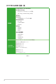
H97-PRO GAMER 仕様一覧 <インタラクティブ・ホームクラウド> ASUS Media Streamer - PCからスマートTVにストリーミング配信 - iOS 7.0以上 / Android™4.0以上に対応 Push Notice - PCの状態をスマートデバイスに通知 UEFI BIOS EZ Mode - O.C. Tuner 搭載機能 - CrashFree BIOS 3 - EZ Flash 2 Q-Design - Q-Shield - Q-DIMM - Q-Slot ASUS 独自機能 - USB 3.0 Boost - AI Suite 3 - Disk Unlocker - AI Charger PS/2コンボポート×1(キーボード/マウス両対応) 光デジタルS/PDIF出力ポート×1 DVI-D 出力ポート×1 バックパネル インターフェース HDMI 出力ポート×1 VGA 出力ポート×1 LAN ポート×1 (RJ-45タイプ) USB 2.0ポート×2 USB 3.
H97-PRO GAMER 仕様一覧 USB 3.0コネクター×1(19ピン) USB 2.0コネクター×3 (9ピン) システムパネルコネクター×1 デジタルオーディオコネクター×1 フロントパネルオーディオコネクタ−×1 SATA 6Gb/s コネクター×4 M.2スロット×1(Key M、Type 2260/2280、Socket3) SATA Expressポート×1 (SATA 6Gb/s ポート×2) 基板上 インターフェース 4ピン CPUファンコネクター×1(DC制御 / PWM制御 対応) 4ピン CPUオプションファンコネクター×1 4ピン ケースファンコネクター×3 (DC制御 対応) 温度センサーコネクター×1 シリアルポートコネクター ×1 TPM ヘッダー ×1 Clear CMOSジャンパ×1 24ピンATX電源コネクター×1 8ピンEPS 12V電源コネクター×1 BIOS機能 64 Mb Flash ROM、UEFI AMI BIOS、PnP、DMI 2.7、WfM 2.0、SM BIOS 2.8、 ACPI 5.
x
製品の概要 1.1 マザーボードの概要 1.1.1 始める前に 1 マザーボードのパーツの取り付けや設定変更の際は、次の事項に注意してください。 1.
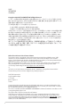
H97-PRO GAMER この面をケースの 背面に合わせます。 1.2.3 マザーボードのレイアウト 1 2 3 2 4 24.4cm(9.6in) CPU_FAN DIGI +VRM CPU_OPT H97-PRO GAMER CPU_LED PCIEX1_1 Intel I218V 30.5cm(12in) EATXPWR DRAM_LED VGA_LED 5 6 SATA6G_12 PCIEX16_1 PCI1 ASM 1083 SATA6G_34 Intel® H97 PCIEX1_2 7 SATAEXPRESS (SATA6G_56) BATTERY PCIEX16_2 BOOT_DEVICE_LED SUPREMEFX ALC 1150 2 1 M.
1.2.4 レイアウトの内容 コネクター/ジャンパ/スロット/スイッチ/LED ページ 1. ATX電源コネクター (24ピン EATXPWR、8ピン EATX12V) 1-17 2. CPU、オプション、ケース ファンコネクター (4ピン CPU_FAN、4ピン CPU_OPT、4ピン CHA_FAN1-3) 1-16 3. CPUソケット: LGA1150 1-3 4. DDR3 DIMMスロット 1-7 5. USB 3.0 コネクター (20-1ピン USB3_12) 1-19 6. M.2スロット (M.2) 1-22 7. Intel® H97 SATA 6Gb/s コネクター (7ピン SATA6G_1-6、SATA6G_56; SATAEXPRESS) 1-20 8. スタンバイ電源LED (SB_PWR) 1-23 9. システムパネルコネクター (20-8ピン PANEL) 10. USB 2.0 コネクター (10-1ピン USB910、USB1314、USB34) 1-21 1-19 11.
CPUを取り付ける際は、必ず電源ケーブルをコンセントから抜いて行なってください。 1.3.
4 5 C A B 1.3.
CPUクーラーの取り付け手順 1 2 A B B A 3 4 CPUクーラーの取り外し手順 1 2 A B B A 1-6 Chapter 1: 製品の概要
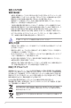
1.4 システムメモリー 1.4.1 概要 本製品には、DDR3 メモリーに対応したDIMMスロットが4基搭載されています。 DDR3メモリーはDDR2メモリーと同様の大きさですが、DDR2メモリースロットに誤って取り付け ることを防ぐため、ノッチの位置は異なります。DDR3メモリーは電力消費を抑えて性能を向上さ せます。 DIMM_B1 DIMM_B2 DIMM_A1 DIMM_A2 1.65Vを超過する電圧の必要なメモリーを取り付けるとCPUが損傷することがあります。1.65V 未満の電圧を必要とするメモリーを取り付けることをお勧めします。 H97-PRO GAMER H97-PRO GAMER 240-pin DDR3 DIMM sockets 1.4.
1.4.3 • デフォルト設定のメモリー動作周波数はメモリーのSPDにより異なります。デフォルト設定 では、特定のメモリーはオーバークロックしてもメーカーが公表する値より低い値で動作 する場合があります。メーカーが公表する値、またはそれ以上の周波数で動作させる場合 は、 「2.5 Ai Tweaker メニュー」を参照し手動設定してください。 • すべてのスロットにメモリーモジュールを取り付ける場合やオーバークロックを行なう場 合は、安定した動作のために適切な冷却システムをご使用ください。 • 最新のQVLはASUSオフィシャルサイトをご覧ください。 (www.asus.
H97-PRO GAMER マザーボードメモリーQVL (推奨ベンダーリスト) DDR3 2400MHz ベンダー パーツNo. サイズ SS/DS AMD AG34G2401G1S 4GB SS チップ ブランド チップ No. タイミング N/A N/A 11-12-12-31 1.65V メモリースロット サポート (オプション) 2 • 電圧 4 • DDR3 2250MHz ベンダー パーツNo. サイズ KINGSTON KHX2250C9D 3T1K2/4GX(XMP) 4GB (2x 2GB) SS/DS チップ ブランド チップ No. タイミング 電圧 DS N/A N/A 1.65V 9-9-9-24-33 メモリースロット サポート (オプション) 2 4 • • DDR3 2200MHz ベンダー パーツNo. サイズ SS/DS チップ ブランド チップ No. タイミング 電圧 GEIL GET38GB2200C 9ADC(XMP) 4GB DS N/A N/A 1.
DDR3 1600MHz ベンダー パーツNo. APACER CORSAIR CORSAIR CORSAIR G.SKILL 78.BAQEJ.9LK0C(XMP) TR3X6G1600C8D G(XMP) CML16GX3M2A1600C10 CMZ8GX3M1A1600C10(XMP) F3-12800CL9D-4GBRL(XMP) F3-12800CL10SG.SKILL 8GBXL(XMP) KINGSTON KHX1600C9D3K2/8GX(XMP) KINGSTON KHX1600C9D3P1K2/8G KINGSTON KHX1600C9D3K2/8GX MICRON MT16JTF1G64AZ-1G6E1 ADATA ADDU1600W4G11-B ADATA AX3U1600W4G9-DB(XMP) ADATA AX3U1600W8G9-DB サイズ SS/ チップ DS ブランド チップ No.
1.5.1 拡張カードを取り付ける 手順 1. 拡張カードを取り付ける前に、拡張カードに付属するマニュアルをよく読み、拡張カードの 使用に必要なハードウェアの設定を行なってください。 2. マザーボードをケースに取り付けている場合は、ケースのカバーを開けます。 3. 拡張カードを取り付けるスロットのブラケットカバーを取り外します。ネジは後で使用する ので、大切に保管してください。 4. 拡張カードの端子部分をスロットに合わせ、拡張カードがスロットに完全に固定されるま でしっかり挿し込みます。 5. 拡張カードのブラケット部をネジで固定します。 6. カバーを取り付け、ケースを閉じます。 1.5.2 拡張カードを設定する 拡張カードを取り付けた後、ソフトウェアの設定を行い拡張カードを使用できるようにします。 1. システムを起動し、必要に応じてUEFI BIOSの設定を行います。UEFI BIOS Utilityの詳細に ついては、Chapter 2 をご覧ください。 2.
PCI Express 2.0 x16 スロット(PCIEX16_2)はPCI Express 2.0 x1 スロット(PCIEX1_1/2)、M.2スロ ット(PCIe mode)と同じ帯域を使用しています。詳しくは「2.6.
1.6 1. ジャンパ Clear CMOS ジャンパ (3ピン CLRTC) このジャンパは、CMOSのリアルタイムクロック(RTC)RAMを消去するためのものです。 CMOS RTC RAMを消去することにより、システム時計、システムパスワード、および設定パ ラメータを工場出荷時の状態に戻すことができます。システムパスワードなどのシステム 情報を含むCMOS RAM データの維持は、マザーボード上のボタン型電池により行われて います。 H97-PRO GAMER 1 CLRTC 2 Normal (Default) 2 3 Clear RTC H97-PRO GAMER Clear RTC RAM CMOS RTC RAMを消去する手順 1. コンピューターの電源をオフにし電源ケーブルをコンセントから抜きます。 2. ジャンパキャップをピン 1-2(初期設定)からピン 2-3 に移動させショートさせます。5~10 秒ほど待ってから、再びピン 1-2にキャップを戻します。 3. 電源ケーブルを差し込み、コンピューターの電源をオンにします。 4.
1.7 コネクター 1.7.1 パックパネルコネクター 1. PS/2 コンポポート: PS/2接続のキーボードまたはマウスを接続します。 2. 光デジタルS/PDIF出力ポート: アンプスピーカーやヘッドホンなどのS/PDIF対応デバイス を接続します。 3. VGA出力ポート: VGAモニター等のVGA対応デバイスを接続します。 4.
5. USB 2.0ポート7/8: USB 2.0デバイスを接続することができます。 6. HDMI出力ポート: HDMIデバイスを接続します。著作権保護技術の1つである HDCP (High-bandwidth Digital Content Protection)にも対応していますので、HD DVD、Bluray、その他の著作権保護コンテンツの再生も可能です。 7. DVI-D出力ポート: DVI-Dと互換性のあるデバイスを接続します。DVI-D信号をRGB信号に 変換してCRTモニターに出力することはできません。また、DVI-DはDVI-I とは互換性があ りません。 8. USB 3.0ポート3/4/5/6: USB 3.0デバイスを接続することができます。 9. • Windows® 7 環境下では、Intel®チップセットのUSB 3.0ポートはドライバーをインストール した場合にのみUSB 3.0として動作します。 • USB 3.0 デバイスを最高のパフォーマンスでご使用いただくために、USB 3.0 対応デバイ スはUSB 3.
1.7.2 1. 内部コネクター シリアルポートコネクター (10-1ピン COM) シリアルポート(COMポート)用コネクターです。シリアルポートモジュールのケーブルを接続 し、モジュールをバックパネルの任意のスロットに設置します。 PIN 1 DCD TXD GND RTS RI RXD DTR DSR CTS COM H97-PRO GAMER H97-PRO GAMER Serial port (COM) connector シリアルポートモジュールは別途お買い求めください。 2.
3. ATX電源コネクター (24ピン EATXPWR、8ピン EATX12V) ATX電源プラグ用のコネクターです。電源プラグは正しい向きでのみ取り付けられるように 設計されています。正しい向きでしっかりと挿し込んでください。 A A B EATX12V EATXPWR PIN 1 +12V DC +12V DC +12V DC B +12V DC GND GND GND GND H97-PRO GAMER +3 Volts +12 Volts +12 Volts +5V Standby Power OK GND +5 Volts GND +5 Volts GND +3 Volts +3 Volts GND +5 Volts +5 Volts +5 Volts -5 Volts GND GND GND PSON# GND -12 Volts +3 Volts PIN 1 H97-PRO GAMER ATX power connectors 4. • システムの快適なご利用のために、容量 350W以上のATX 12V バージョン2.
5. フロントパネルオーディオコネクター(10-1ピン AAFP) H97-PRO GAMER NC AGND NC NC SENSE2_RETUR AGND NC SENSE1_RETUR PCケースのフロントパネルオーディオI/Oモジュール用コネクターで、HDオーディオ及び AC’97オーディオをサポートしています。オーディオ I/Oモジュールケーブルをこのコネクタ ーに接続します。 AAFP HD-audio-compliant pin definition MIC2 MICPWR Line out_R NC Line out_L PORT1 L PORT1 R PORT2 R SENSE_SEND PORT2 L PIN 1 Legacy AC’97 compliant definition H97-PRO GAMER Front panel audio connector 6.
7. USB 3.0コネクター (20-1ピン USB3_12) USB 3.0ポート用コネクターです。USB 3.0の転送速度は理論値でUSB 2.0の約10倍となり、 プラグアンドプレイに対応しているので接続も非常に簡単です。ご利用のPCケースやデバ イスが9ピン+10ピンのピンヘッダーに対応したUSB 3.0 デバイスの場合は、このコネクタ ーに接続して利用することが可能です。 USB3_12 H97-PRO GAMER PIN 1 USB3+5V IntA_P2_SSRXIntA_P2_SSRX+ GND IntA_P2_SSTXIntA_P2_SSTX+ GND IntA_P2_DIntA_P2_D+ USB3+5V IntA_P1_SSRXIntA_P1_SSRX+ GND IntA_P1_SSTXIntA_P1_SSTX+ GND IntA_P1_DIntA_P1_D+ GND H97-PRO GAMER USB3.0 Front panel connector 8. • USB 3.
9.
10.
11. M.2スロット (M.2) M.2規格のSSDを取り付けることができます。本製品のM.2スロットは、SATAインターフェー ス、PCIeインターフェース両規格のSSDに対応しています。 M.2(SOCKET3) H97-PRO GAMER H97-PRO GAMER M.2(SOCKET3) • ・ • M.2スロットは、Type 2260/2280サイズのKeyM のSocket3に対応します。 M.2スロットは、SATA modeの場合はSATA 6Gb/s 第4ポート(SATA6G_4) と、PCIe mode の場合はPCI Express 2.0 x1 スロット(PCIEX1_1/2) と同じ帯域を使用しています。詳しくは 「2.6.3 PCHストレージ設定」 と 「2.6.7 オンボードデバイス設定」をご覧ください。 PCIeインターフェースのM.
1.8 1.
1.9 ソフトウェア 1.9.1 OSをインストールする 本製品は、Windows® 7 / Windows® 8 / Windows® 8.1 オペレーティングシステムをサポートして います。ハードウェアの機能を最大限に活用するために、OSは定期的にアップデートを実行する ことをおすすめします。 1.9.2 • 本マニュアルで使用されているイラストや画面は実際とは異なる場合があります。 • 操作方法や設定方法はご使用のオペレーティングシステムにより異なる場合があります。 詳しい操作方法などは、ご利用のオペレーティングシステムマニュアルをご覧ください。 サポートDVD情報 マザーボードに付属のサポートDVDには、マザーボードを利用するために必要なドライバー、ア プリケーション、ユーティリティが収録されています。 サポートDVDの内容は、予告なしに変更する場合があります。最新のドライバーやユーティリテ ィなどは、ASUSオフィシャルサイトをご覧ください。 (http://www.asus.
2 UEFI BIOS設定 2.1 UEFI BIOS更新 ASUSオフィシャルサイトでは最新のUEFI BIOSを公開しています。UEFI BIOSの更新により、システ ムの安定性、互換性、パフォーマンスの向上が期待できます。ただし、UEFI BIOSの更新には常にリ スクが伴います。使用上、現在の状態で特に問題がない場合はUEFI BIOSの更新を行わないでく ださい。不適切な更新はシステムが起動しない、または不安定になるといった問題の原因となり ます。UEFI BIOSの更新が必要な場合は、本書に記載の指示に従い、慎重に行なってください。 最新のBIOSファイルはASUSオフィシャルサイトからダウンロードすることができます。 (http://www.asus.com) 次のユーティリティで本マザーボードのUEFI BIOSの更新と管理が可能です。 1. EZ Update: Windows® 環境でUEFI BIOS更新を行います。 2. ASUS EZ Flash 2: USBメモリーを使用してUEFI BIOS更新を行います。 3.
2.1.2 ASUS EZ Flash 2 ASUS EZ Flash 2 Utility は、起動フロッピーディスクまたはOSベースのユーティリティを使うこと なく、UEFI BIOSを短時間で更新することができます。 このユーティリティをご利用になる前に、最新のBIOSをASUSのオフィシャルサイトからダウンロ ードしてください。 (http://www.asus.com) EZ Flash 2 を使用してUEFI BIOSを更新する 2-2 1. 最新のBIOSファイルを保存したUSBメモリーをシステムにセットします。 2. UEFI BIOS Utility のAdvanced Mode を起動し、Tool メニューの「ASUS EZ Flash 2 Utility」 を選択します。 3. キーボードまたはマウスを使用して、Driver Infoフィールドの最新のBIOSファイルを保存し たUSBメモリードライブを選択します。操作するフィールドはキーボードので切り替 えることができます。 4.
2.1.3 ASUS CrashFree BIOS 3 ASUS CrashFree BIOS 3 はUEFI BIOSの自動復旧ツールで、更新時に障害を起こした場合や破損 したUEFI BIOSを復旧します。破損したUEFI BIOSはサポートDVD、またはBIOSファイルを保存した USBメモリーを使用して復旧することができます。 • 本機能を使用する前に、 リムーバブルデバイスに保存されたBIOSファイルのファイル名を 「H97PROG.CAP」に変更してください。 • サポートDVDに収録のBIOSファイルは最新のものではない場合があります。最新バージョ ンのBIOSファイルは弊社サイトで公開しております。USBメモリーにダウンロードしてご使 用ください。 (http://www.asus.com) UEFI BIOSを復旧する 手順 1. システムの電源をオンにします。 2.
DOS環境でシステムを起動する 1. 最新のBIOSファイルとBIOS Updater を保存したUSBメモリーをUSBポートに接続します。 2. コンピューターを起動し、POST中に を押します。 3. 続いてBoot Device Select Menu が表示されたらサポートDVDを光学ドライブに挿入し、 カーソルキーで光学ドライブを選択し<Enter>を押します。 Please select boot device: E1: ASUS DVD-E818A6T (4069MB) USB DISK 2.0 (3824MB) UEFI: (FAT) USB DISK 2.0 (3824MB) Enter Setup and to move selection ENTER to select boot device ESC to boot using defaults 4. 画面に次のようなメッセージが表示されたら、5秒以内にを押しFreeDOSを起動し ます。 ISOLINUX 3.
2. BIOS Updaterが起動し、次のような画面が表示されます。 ASUSTeK BIOS Updater for DOS V1.30 [2014/01/01] Current ROM BOARD: H97-PRO GAMER VER: 0209 (H :00 B :00) DATE: 06/04/2014 PATH: ドライブ パネル Update ROM BOARD: Unknown VER: Unknown DATE: Unknown C:\ C: D: FORMAN~1 H97PROG.CAP
8390626 2014-06-04 21:14:34 ファイル パネル Note [Enter] Select or Load [Up/Down/Home/End] Move [Tab] Switch [Esc] Exit [V] Drive Info 3.2.
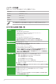
2.2.1 EZ Mode デフォルト設定では、UEFI BIOS Utilityを起動すると、EZ Mode 画面が表示されます。EZ Mode で は、基本的なシステム情報の一覧が表示され、表示言語やシステムパフォーマンスモード、ブート デバイスの優先順位などが設定できます。Advanced Mode を開くには、 「Exit/Advanced Mode」 をボタンをクリックし、 「Advanced Mode」を選択するかを押します。 UEFI BIOS Utility起動時に表示する画面は変更することができます。詳細はセクション「2.
Advanced Mode Advanced Modeでは、オーバークロックや各種電圧の調整から、オンボード機能の有効/無効な ど詳細な設定を行うことができます。Advanced Modeの各項目の詳細については、以降のページ をご覧ください。 Advanced ModeからEZ Modeへ切り替えるにはを押すか、画面右下の「EZ Mode(F7)」ボ タンを押すことで簡単に切り替えることができます。 構成フィールド クイックメニュー ハードウェアモニター メニューバー サブメニュー 2-8 詳細情報 メニュー ドロップダウンリスト スクロールバー Last Modified EZ Mode Chapter 2: UEFI BIOS 設定
メニューバー 画面上部のメニューバーには次の項目があり、主な設定内容は以下のとおりです。 Main 登録したお気に入り項目 基本システム設定 Ai Tweaker オーバークロック関連 My Favorites Advanced 拡張システム設定 Monitor システム温度/電力状態の表示、およびファンの設定 Boot システム起動関連 Tool 独自機能 終了メニュー、及びデフォルト設定のロード Exit メニュー メニューバーの各項目を選択することにより、各項目に応じた設定メニューが表示されます。例え ば、メニューバーで「Main」を選択すると、 「Main」の設定メニューが画面に表示されます。 サブメニュー サブメニューが含まれる項目の前には、 「>」マークが表示されます。サブメニューを表示するに は、マウスで項目を選択するか、カーソルキーで項目を選択し、を押します。 ドロップダウンリスト マウスで項目を選択するか、カーソルキーで項目を選択しを押すと、設定可能なオプショ ンがドロップダウンリストに表示されます。 スクロールバー 設定項目が画
2.3 My Favorites 頻繁に使用する項目をお気に入りとして登録することで、画面の切り替えなどの面倒な操作をせ ずに一画面で各種設定を変更することができます。 お気に入り項目を追加する 手順 をクリックし、Setup 1. Advanced Modeでキーボードのを押すか Tree Mapを開きます。 2. Setup Tree Mapでお気に入りに登録したい項目を選択します。 追加した項目 メインメニュー パネル サブメニューパネル 3. まず、メインメニューパネルでカテゴリーを選択し、次にサブメニューパネルでお気に入り を に追加したい項目を選択します。お気に入りに追加したい項目でを押すか クリックして項目を追加します。 次の項目はお気に入りに追加することはできません: 2-10 ・ ユーザー管理項目(システム言語や起動デバイス優先順位など) ・ ユーザー設定項目(システム日付や時間など) 4. 「Exit (ESC)」をクリックするか、を押してメインメニューに戻ります。 5.
2.4 メインメニュー 2.4.1 System Language [English] Advanced Modeのメインメニューでは、マザーボード、CPU、メモリーの基本的な情報を表示す る他に、表示言語やセキュリティの設定を行うことができます。 UEFI BIOS Utility の表示言語を選択することができます。 設定オプション: [ English] [Русский][한국어] 2.4.2 [Español] System Date [Day xx/xx/xxxx] システムの日付を設定します。 2.4.3 System Time [xx:xx:xx] システムの時間を設定します。 2.4.4 Security システムセキュリティ設定の変更が可能です。 • • パスワードを忘れた場合、CMOSクリアを実行しパスワードを削除します。Clear CMOS ジャンパの位置はセクション「1.
Administrator Password 管理者パスワードを設定した場合は、システムにアクセスする際に管理者パスワードの入力を要 求するように設定することをお勧めします。 管理者パスワードの設定手順 1. 「Administrator Password」を選択します。 2. 「Create New Password」ボックスにパスワードを入力し、を押します。 3. パスワードの確認のため、 「Confirm New Password」ボックスに先ほど入力したパスワー ドと同じパスワードを入力し、[OK]ボタンをクリックします。 管理者パスワードの変更手順 1. 「Administrator Password」を選択します。 2. 「Enter Current Password」ボックスに現在のパスワードを入力し、を押します。 3. 「Create New Password」ボックスに新しいパスワードを入力し、を押します。 4.
2.
Target CPU Turbo-Mode Frequency : xxxxMHz 設定保存後のTurbo boost時最大CPU動作周波数の目安が表示されます。 Target DRAM Frequency : xxxxMHz 設定保存後の最大メモリー動作周波数の目安が表示されます。 Target Cache Frequency : xxxxMHz 設定保存後のCPUキャッシュ動作周波数の目安が表示されます。 Target DMI/PCIE Frequency : xxxxMHz 設定保存後のベースクロック (基本動作周波数)の目安が表示されます。 Target iGPU Frequency : xxxxMHz 設定保存後の統合グラフィックスの動作周波数の目安が表示されます。 2.5.
2.5.2 CPU Ratio Unlock [Disabled] 本項目を有効にすることで、Intel K-Series CPUでオーバークロック向けの内部倍率ロック機能の 制限を解除することができます。 設定オプション: [Enabled] [Disabled] 本製品では、取り付けられたCPU、マザーボードに搭載のチップセット、UEFIおよびファームウェ アに基づいて内部倍率ロック解除機能をサポートすることができます 2.5.
2.5.8 Max. CPU Graphics Ratio [Auto] CPU統合型グラフィックス(Intel HD Graphics) の最大動作倍率を設定します。 [Auto] CPUが内蔵するGPUの最大動作クロックを、システムの負荷状態に応じて自動 的に最適化します。 [Manual] CPUが内蔵するGPUの最大動作クロックを、手動で設定します。数値の調節は <+> <->で行います。設定範囲は 取り付けたCPUにより異なります。 2.5.9 GPU Boost [Keep Current Settings] 統合型グラフィックスの動作周波数とコア電圧を自動的に調整しオーバークロックします。 [Keep Current Settings] 現在の設定を維持します。 [Enabled] 統合型グラフィックスの動作周波数とコア電圧を自動で調整します。 2.5.
DRAM WRITE Recovery Time [Auto] 設定オプション: [Auto] [1 DRAM Clock] – [16 DRAM Clock] DRAM READ to PRE Time [Auto] 設定オプション: [Auto] [1 DRAM Clock] – [15 DRAM Clock] DRAM FOUR ACT WIN Time [Auto] 設定オプション: [Auto] [1 DRAM Clock] – [255 DRAM Clock] DRAM WRITE to READ Delay [Auto] 設定オプション: [Auto] [1 DRAM Clock] – [15 DRAM Clock] DRAM CKE Minimum pulse width [Auto] 設定オプション: [Auto] [1 DRAM Clock] – [15 DRAM Clock] DRAM CAS# Write Latency [Auto] 設定オプション: [Auto] [1 DRAM Clock] – [31 DRAM Clock] RTL IOL control DRAM RTL In
DRAM IO-L (CHA_R0D1) [Auto] 設定オプション: [Auto] [1] - [15] DRAM IO-L (CHA_R1D0 [Auto] 設定オプション: [Auto] [1] - [15] DRAM IO-L (CHA_R1D1 [Auto] 設定オプション: [Auto] [1] - [15] DRAM IO-L (CHB_R0D0 [Auto] 設定オプション: [Auto] [1] - [15] DRAM IO-L (CHB_R0D1 [Auto] 設定オプション: [Auto] [1] - [15] DRAM IO-L (CHB_R1D0 [Auto] 設定オプション: [Auto] [1] - [15] DRAM IO-L (CHB_R1D1 [Auto] 設定オプション: [Auto] [1] - [15] Third Timings tRDRD [Auto] 設定オプション: [Auto] [1 DRAM Clock] – [7 DRAM Clock] tRDRD_dr [Auto] 設定オプション: [Auto] [1 DRAM Clock] – [15 DRAM
tRDWR [Auto] 設定オプション: [Auto] [1 DRAM Clock] – [31 DRAM Clock] tRDWR_dr [Auto] 設定オプション: [Auto] [1 DRAM Clock] – [31 DRAM Clock] tRDWR_dd [Auto] 設定オプション: [Auto] [1 DRAM Clock] – [31 DRAM Clock] Misc.
2.5.
2.5.
CPU Internal Power Configuration CPU Integrated VR Efficiency Management [Auto] CPUが低電力状態にあるときの省電力性能を向上させる機能を設定します。こ の項目を[High Performance]に設定すると、統合電圧レギュレーターは常に CPUが高いパフォーマンスを発揮できるよう動作します。 設定オプション: [Auto] [High Performance] [Balanced] Power Decay Mode [Auto] アイドル時に統合VRMを省電力モードに切り替え、省電力パフォーマンスを向 上させる機能の有効/無効を設定します。 設定オプション: [Auto] [Disabled] [Enabled] Idle Power-in Response [Auto] 統合VRMのアイドル状態に移行する際のスルーレートを設定します。 設定オプション: [Auto] [Regular] [Fast] Idle Power-out Response [Auto] 統合VRMがアイドル状態から復帰する際のスルーレートを設定しま
2.5.14 Extreme Over-voltage [Disabled] CPUに搭載されている過電圧保護回路の保護機能解除の有効/無効を設定します。この項目を [Enabled]に設定することで、極限までオーバークロックを行なうことができますが、CPUが破損す る可能性は非常に高くなります。 設定オプション: [Disabled] [Enabled] 2.5.15 CPU Core Voltage [Auto] CPUコアに供給する電圧の調整方法を設定します。 設定オプション: [Auto] [Manual Mode] [Offset Mode] 次の項目は「CPU Core Voltage」を[Manual Mode] にすると表示されます。 CPU Core Voltage Override [Auto] CPUコアに供給する電圧の調整方法を設定します。 設定範囲は 0.001V〜1.920Vで、0.
2.5.17 CPU Graphics Voltage [Auto] 統合型グラフィックスコアに供給する電圧の制御方法を設定します。 設定オプション: [Auto] [Manual Mode] [Offset Mode] [Adaptive Mode] CPU Graphics Voltage Override [Auto] この項目は「CPU Graphics Voltage」を [Manual Mode] にすると表示されます。統合型グラフィック スコアに供給する電圧を設定します。 設定範囲は0.001V〜1.920Vで、0.
2.5.20 CPU Digital I/O Voltage Offset Mode Sign [+] [+] CPU Digital I/O Voltage Offsetで指定した値の電圧を上げます。 [–] CPU Digital I/O Voltage Offsetで指定した値の電圧を下げます。 CPU Digital I/O Voltage Offset [Auto] CPUのデジタルインターフェース回路に供給する電圧をオフセット調整します。 設定範囲は 0.001V〜0.999Vで、0.001V刻みで調節します。 2.5.
2.5.27 DRAM DATA REF Voltage on CHA [Auto] チャンネルAのメモリーデータ信号の基準となる電圧を設定します。設定範囲は 0.395x 〜 0.630x で、0.005x刻みで調節します。 2.5.28 DRAM DATA REF Voltage on CHB [Auto] チャンネルBのメモリーデータ信号の基準となる電圧を設定します。設定範囲は 0.395x 〜 0.630x で、0.005x刻みで調節します。 2.5.29 CPU Spread Spectrum [Auto] 動作周波数を変調させることで信号伝送時の電磁波を低減させ、通常動作時の動作を安定させ るスペクトラム拡散機能の有効/無効を設定します。 * オーバークロック時には、この項目を[Disabled]に設定することで、システムの動作が安定する 場合があります。 [Auto] [Disabled] [Enabled] 2.
2.6.
CPU Power Management Configuration CPUの動作倍率やEnhanced Intel SpeedStep®の設定をすることができます。 Enhanced Intel SpeedStep Technology [Enabled] CPUの負荷に応じて動作周波数や電圧を段階的に変化させることで消費電力と発熱を抑え る、拡張版 Intel SpeedStep テクノロジー(EIST)の有効/無効を設定します。 [Disabled] CPUは定格速度で動作します。 [Enabled] OSが自動的にCPUの電圧とコア周波数を調節します。これにより電 力消費と発熱量を抑えることができます。 Turbo Mode [Enabled] CPUにかかる負荷や発熱の状況に応じて動作クロックを変化させる、Intel®Turbo Boost Technology の有効/無効を設定します。 設定オプション: [Enabled] [Disabled] CPU C-States [Auto] CPUの省電力機能Cステートの設定をします。 設定オプション: [Auto] [Enabled] [Disab
2.6.
2.6.3 PCHストレージ設定 UEFI BIOS Utilityの起動中は、UEFI BIOSは自動的にシステムに取り付けられたSATAストレージ デバイスを検出します。SATAストレージデバイスが取り付けられていない場合はポート名の横に 「Empty」 と表示されます。 M.2 SATA mode [Disabled] M.2スロットのSATA動作モードの有効/無効を設定します。この項目はSATAインターフェースの M.2 デバイスを取り付けた場合に表示されます。 [Enabled] M.2スロットはSATA modeで動作します。SATA6Gb/s 第4ポート(SATA6G_4)は 無効です。 [Disabled] M.
2.6.
Memory Configuration Memory Scrambler [Enabled] 動作周波数の高いメモリーにおける安定性を向上させることができる、メモリースクランブ ラー機能の有効/無効を設定します。 設定オプション: [Enabled] [Disabled] Memory Remap [Enabled] 64bit オペレーティングシステムにおいて4GB以上のアドレス空間を再割り当て(リマッピン グ)する機能の有効/無効を設定します。 設定オプション: [Enabled] [Disabled] 2.6.
2.6.6 プラットフォーム設定 PCH (Platform Controller Hub) に関する設定をすることができます。 PCI-E Native Power Management [Disabled] この項目を有効に設定することで、PCI Expressの省電力機能を強化し、OS環境下でASPMを実行 することが可能になります。 設定オプション: [Disabled] [Enabled] 次の項目は「PCI-E Native Power Management」を [Enabled] に設定すると表示されます。 Native ASPM [Disabled] [Enabled] ACPI 3.
Front Panel Type [HD Audio] フロントパネル用音声入出力端子の動作モードを選択します。 [HD Audio] HDモードで動作します。 [AC97] AC’97モードで動作します。 SPDIF Out Type [SPDIF] S/PDIF端子からの出力信号タイプを設定します。 [SPDIF] S/PDIFモードで出力します。 [HDMI] HDMIモードで出力します。 SupremeFX Lighting LED [Enabled] オンボードのSupremeFX LEDの有効/無効を設定します。 設定オプション: [Enabled] [Disabled] M.2 PCIe mode [Disabled] M.2スロットのPCIe動作モードの有効/無効を設定します。この項目はPCIeインターフェースのM.2 デバイスを取り付けた場合に表示されます。 [Enabled] M.2スロットはPCIe modeで動作します。PCI Express 2.0 x16 スロット (PCIEX16_2) はx2モード で動作し、PCI Express 2.
2.6.
2.
2.7.1 Qfan Tuning マザーボードに取り付けられたファンの最低回転数を計測し、各ファンの最小デューティサイクル を自動で設定します。 2.7.2 CPU/ MB/VRM/ PCH CORE/ SENSOR Temperature [xxxºC/ xxxºF] オンボードハードウェアモニターはシステムの温度を自動検出し摂氏/華氏で表示します。温度の 検出を停止する場合は[Ignore]に設定します。 2.7.3 CPU / CPU Optional / Chassis Fan Speed [xxxx RPM] オンボードハードウェアモニターは各ファンのスピードを自動検出し、RPMの単位で表示します。 マザーボードにファンが接続されていない場合は、[N/A] と表示されます。なお、[Ignore] にする と、表示されなくなります。 2.7.4 CPU Input (VCCIN) / CPU Core / 3.
2.7.
2.7.
Allow Fan Stop [Disabled] 熱源温度が下限温度を下回った場合にファンを停止する機能の有効/無効を設定します。 設定オプション: [Disabled] [Enabled] 2.7.
2.8 ブートメニュー システム起動に関する設定を行うことができます。 画面をスクロールすることですべての項目を表示することができます。 2.8.
SATA Support [All Devices] [All Devices] SATAポートに接続されたすべてデバイスはPOST時に利用可能です。POST 完了までの時間は遅くなります。 [Hard Drive Only] SATAポートに接続されたHDD/SSDのみPOST時に検出します。 [Boot Drive Only] SATAポートに接続されたブートドライブのみPOST時に検出します。 USB Support [Partial Initialization] [Disabled] すべてのUSBデバイスはOSが実行されるまで無効状態になります。最も 早くPOSTを完了することが可能です。 [Full Initialization] すべてのUSBデバイスはPOST時に利用可能です。POST完了までの時間 は遅くなります。 [Partial Initialization] POST時間を短縮するためにキーボードとマウスを接続したUSBポート のみをPOSTで検出します。 PS/2 Keyboard and Mouse Support [Auto] Fast Boot
2.8.3 Bootup NumLock State [On] システム起動時、キーボードのNumLock 機能の有効/無効を設定します。 設定オプション: [Disabled] [Enabled] 2.8.4 Wait for ‘F1’ If Error [Enabled] POSTプロセス中にエラーが発生した際、キーを押すまでシステムを待機させる機能の有 効/無効を設定します。 設定オプション: [Disabled] [Enabled] 2.8.5 Option ROM Messages [Force BIOS] [Force BIOS] サードパーティのROMメッセージをブートシーケンス時に強制的に表示させ ます。 [Keep Current] アドオンデバイスの設定に従い、サードパーティROMメッセージを表示させます。 2.8.
Boot from Network Devices [Legacy OPROM first] 起動に使用するネットワークデバイスの優先タイプを選択します。起動時間を短縮する場合は [Ignore] を選択します。 設定オプション: [Legacy OPROM first] [UEFI driver first] [Ignore] Boot from Storage Devices [Legacy OPROM first] 起動に使用するストレージデバイスの優先タイプを選択します。起動時間を短縮する場合は [Ignore] を選択します。 設定オプション: [ Both, Legacy OPROM first] [Both, UEFI first] [Legacy OPROM first] [UEFI driver first] [Ignore] Boot from PCI-E/PCI Expansion Devices [Legacy OPROM first] 起動に使用するPCI Express/PCI 拡張デバイスの優先タイプを選択します。 設定オプション: [Legacy OPROM first]
Delete PK プラットフォームキー (PK) を削除します。PKを削除した場合、Secure Bootは利 用できません。 設定オプション: [Yes] [No] Load Default PK システムにPKをロードします。[Yes]を選択すると、システムのデフォルトのPK がロードされます。 特定のカスタマイズされたUEFI実行ファイルの実行を禁止するため、USBスト レージデバイスからPKをロードするには[No]を選択します。 ロードするファイルは時間ベース認証変数を使用するUEFI可変構造でフォーマットされている 必要があります。 KEK Management KEK(キー交換キーデータベース、またはキー登録キーデータベース)は、署名データベース (db) と失効した署名データベース (dbx) の更新に使用されます。 キー交換キーデータベース (KEK) はMicrosoft® キー登録キーデータベース (KEK) を示します。 Delete the KEK キー交換キーデータベース (KEK) を削除します。 設定オプション: [Yes] [No] Load Default KEK シス
ロードするファイルは時間ベース認証変数を使用するUEFI可変構造でフォーマットされている 必要があります。 DBX Management 失効した署名データベース (dbx) は、信頼されなくなったために読み込みが許可されない アイテムの、失効したイメージが登録されています。 Delete the dbx 失効した署名データベース (dbx) を削除します。 Load Default dbx システムにdbxをロードします。[Yes]を選択すると、システムのデフォルトのdbx がロードされます。特定のカスタマイズされたdbxをUSBストレージデバイスか らロードするには[No]を選択します。 Append Default dbx システムにdbxを追加します。[Yes]を選択すると、システムのデフォルトのdbx が追加されます。特定のカスタマイズされたdbxをUSBストレージデバイスか ら追加するには[No]を選択します。 ロードするファイルは時間ベース認証変数を使用するUEFI可変構造でフォーマットされている 必要があります。 2.8.
2.9 ツールメニュー 2.9.1 ASUS EZ Flash 2 Utility ASUS独自機能の設定をします。マウスで項目を選択するか、キーボードのカーソルキーで項目を 選択し、を押してサブメニューを表示させることができます。 UEFI BIOS更新ツール「ASUS EZ Flash 2 Utility」を起動します。このユーティリティはカーソル キーとを使用して操作します。 詳細はセクション「2.1.2 ASUS EZ Flash 2」をご参照ください。 Setup Animator [Enabled] UEFI BIOS Utilityの画面切り替えアニメーション効果の有効/無効を設定します。 設定オプション: [Disabled] [Enabled] 2.9.
2.9.3 ASUS SPD Information DIMM Slot # [Slot 1] メモリースロットに設置されたメモリーモジュールのSPD (Serial Presence Detect) 情報を読み出 して表示します。 設定オプション: [DIMM_A1] [DIMM_A2] [DIMM_B1] [DIMM_B2] 2.10 終了メニュー 設定の保存や取り消しのほか、デフォルト設定の読み込みを行います。 Load Optimized Defaults すべての設定を初期設定値に戻します。を押すことで同じ動作を行なうことができます。 Save Changes & Reset 設定した変更を保存し、セットアップを終了します。再起動後、設定した値が適用されます。 を押すことで同じ動作を行なうことができます。 Discard Changes & Exit 設定した変更を保存せず、セットアップを終了します。再起動後、設定は変更前の状態に戻ります。 Launch EFI Shell from USB drives EFI Shell アプリケーション (shellx64.
Chapter3 付録 付録 ご注意 Federal Communications Commission Statement 3 This device complies with Part 15 of the FCC Rules. Operation is subject to the following two conditions: • • This device may not cause harmful interference. This device must accept any interference received including interference that may cause undesired operation. This equipment has been tested and found to comply with the limits for a Class B digital device, pursuant to Part 15 of the FCC Rules.
Canadian Department of Communications Statement This digital apparatus does not exceed the Class B limits for radio noise emissions from digital apparatus set out in the Radio Interference Regulations of the Canadian Department of Communications. This class B digital apparatus complies with Canadian ICES-003.
ASUSコンタクトインフォメーション ASUSTeK COMPUTER INC. 住所: 電話(代表) : ファックス(代表) : 電子メール(代表) : Webサイト: テクニカルサポート 電話: ファックス: オンラインサポート: 15 Li-Te Road, Peitou, Taipei, Taiwan 11259 +886-2-2894-3447 +886-2-2890-7798 info@asus.com.tw http://www.asus.com +86-21-38429911 +86-21-58668722, ext.9101# http://www.asus.
3-4 Chapter 3:付録 (510)739-3777/(510)608-4555 800 Corporate Way, Fremont, CA 94539. Asus Computer International Date : Signature : Representative Person’s Name : Jun. 20, 2014 Steve Chang / President This device complies with part 15 of the FCC Rules. Operation is subject to the following two conditions: (1) This device may not cause harmful interference, and (2) this device must accept any interference received, including interference that may cause undesired operation.