Motherboard H97M-E
E9092 First Edition April 2014 Copyright © 2014 ASUSTeK COMPUTER INC. All Rights Reserved. No part of this manual, including the products and software described in it, may be reproduced, transmitted, transcribed, stored in a retrieval system, or translated into any language in any form or by any means, except documentation kept by the purchaser for backup purposes, without the express written permission of ASUSTeK COMPUTER INC. (“ASUS”).
Contents Contents Safety information....................................................................................................... iv About this guide.......................................................................................................... iv Package contents........................................................................................................ vi H97M-E specifications summary...............................................................................
Safety information Electrical safety • To prevent electrical shock hazard, disconnect the power cable from the electrical outlet before relocating the system. • When adding or removing devices to or from the system, ensure that the power cables for the devices are unplugged before the signal cables are connected. If possible, disconnect all power cables from the existing system before you add a device.
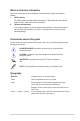
Where to find more information Refer to the following sources for additional information and for product and software updates. 1. ASUS websites The ASUS website provides updated information on ASUS hardware and software products. Refer to the ASUS contact information. 2. Optional documentation Your product package may include optional documentation, such as warranty flyers, that may have been added by your dealer. These documents are not part of the standard package.
Package contents Check your motherboard package for the following items. Motherboard ASUS H97M-E motherboard Cables 2 x Serial ATA 6.0 Gb/s cables Accessories 1 x I/O Shield Application DVD Support DVD Documentation User Guide If any of the above items is damaged or missing, contact your retailer.
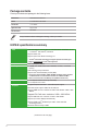
H97M-E specifications summary Storage Intel® H97 Express Chipset with RAID 0, 1, 5, 10 and Intel® Rapid Storage Technology 13 support - 4 x SATA 6.0 Gb/s ports (gray) - 1 x M.2 Socket 3 - Supports Intel® Smart Response Technology, Intel® Rapid Start Technology, and Intel® Smart Connect Technology* * The M.2 Socket 3 supports M Key and type 2260/2280 storage devices. * These functions will work depending on the CPU installed. LAN Realtek® 8111GR Gigabit LAN controller Audio Realtek® ALC887 7.
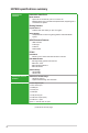
H97M-E specifications summary ASUS Special Features Interactive HomeCloud Media Streamer - Pipe music or movies from your PC to a smart TV - Media Streamer app for portable smartphone/tablet, supporting iOS 7 and Android 4.0 system Gaming Scenario Crystal Sound 2 - Fawless audio that makes you part of the game Steam Support - Compatible with the most fun gaming platform under Windows® system ASUS Exclusive Features - USB 3.
H97M-E specifications summary Internal connectors 1 x 19-pin USB 3.0/2.0 connector supports additional 2 USB ports 3 x USB 2.0/1.1 connectors support additional 6 USB ports 4 x SATA 6.0 Gb/s connectors (gray) 1 x M.
x
Product introduction 1.1 Before you proceed 1 Take note of the following precautions before you install motherboard components or change any motherboard settings. 1.2 • Unplug the power cord from the wall socket before touching any component. • Before handling components, use a grounded wrist strap or touch a safely grounded object or a metal object, such as the power supply case, to avoid damaging them due to static electricity.
Place this side towards the rear of the chassis H97M-E 1.2.3 Motherboard layout 1 2 3 1 4 19.8cm(7.8in) KBMS CPU_FAN CHA_FAN2 DVI_VGA DIGI +VRM 24.4cm(9.6in) USB3_56 EATXPWR USB3_34 DDR3 DIMM_B2 (64bit, 240-pin module) LGA1150 ASM 1442K DDR3 DIMM_B1 (64bit, 240-pin module) HDMI DDR3 DIMM_A2 (64bit, 240-pin module) DDR3 DIMM_A1 (64bit, 240-pin module) EATX12V 2 M.
1.2.4 Layout contents Connectors/Jumpers/Slots/LED 1. CPU and chassis fan connectors (4-pin CPU_FAN, 4-pin CHA_FAN1/2) 2. ATX power connectors (24-pin EATXPWR, 8-pin EATX12V) 3. LGA1150 CPU socket 4. DDR3 DIMM slots 5. USB 3.0 connector (20-1 pin USB3_12) 6. M.2 Socket 3 7. Speaker connector (4-pin SPEAKER) 8. Intel® H97 Serial ATA 6.0 Gb/s connectors (7-pin SATA6G_1-4) 9. Clear RTC RAM (3-pin CLRTC) 10. Chassis intrusion connector (4-1 pin CHASSIS) 11. System panel connector (10-1 pin F_PANEL) 12.
Unplug all power cables before installing the CPU. 1.3.1 • Ensure that you install the correct CPU designed for the LGA1150 socket only. DO NOT install a CPU designed for LGA1155 and LGA1156 sockets on the LGA1150 socket. • Upon purchase of the motherboard, ensure that the PnP cap is on the socket and the socket contacts are not bent. Contact your retailer immediately if the PnP cap is missing, or if you see any damage to the PnP cap/socket contacts/motherboard components.
4 5 C A B 1.3.2 CPU heatsink and fan assembly installation Apply the Thermal Interface Material to the CPU heatsink and CPU before you install the heatsink and fan if necessary.
3 4 To uninstall the CPU heatsink and fan assembly 2 1 A B B A 1.4 System memory 1.4.1 Overview H97M-E DIMM_B1 DIMM_B2 DIMM_A1 DIMM_A2 This motherboard comes with four Double Data Rate 3 (DDR3) Dual Inline Memory Module (DIMM) sockets.
1.4.2 Memory configurations You may install 2GB, 4GB, and 8GB unbuffered non-ECC DDR3 DIMMs into the DIMM sockets. • You may install varying memory sizes in Channel A and Channel B. The system maps the total size of the lower-sized channel for the dual-channel configuration. Any excess memory from the higher-sized channel is then mapped for single-channel operation. • According to Intel CPU spec, DIMM voltage below 1.65V is recommended to protect the CPU.
1.4.
1.5 Expansion slots In the future, you may need to install expansion cards. The following sub‑sections describe the slots and the expansion cards that they support. Unplug the power cord before adding or removing expansion cards. Failure to do so may cause you physical injury and damage motherboard components. 1.5.1 Installing an expansion card To install an expansion card: 1.
IRQ assignments for this motherboard A B C D E F G H PCIEx16_1 shared – – – – – – – PCIEx1_1 PCIEx1_2 PCIEx1_3 LAN – – – shared shared – – – – shared – – – – shared – – – – – – – – – – – – – – – – – – – – shared USB2.0 controller 1 – – – USB2.0 controller 2 USB 3.0 controller HD audio SATA controller 1 SATA controller 2 – – – – – – – – – – – – – – – – – shared – – – – shared – – – – shared shared – – – shared – – – – – – – – 1.
• If the steps above do not help, remove the onboard battery and move the jumper again to clear the CMOS RTC RAM data. After clearing the CMOS, reinstall the battery. • You do not need to clear the RTC when the system hangs due to overclocking. For system failure due to overclocking, use the CPU Parameter Recall (C.P.R.) feature. Shut down and reboot the system, then the BIOS automatically resets parameter settings to default values. 1.7 Connectors 1.7.
Refer to the audio configuration table below for the function of the audio ports in 2.1, 4.1, 5.1, or 7.1-channel configuration. Audio 2.1, 4.1, 5.1, or 7.1-channel configuration Port Headset 2.1-channel Light Blue (Rear panel) Line In Lime (Rear panel) Line Out Pink (Rear panel) Mic In Rear Speaker Out Front Speaker Out Mic In Pink (Front panel) – – 4.1-channel 5.1-channel Rear Speaker Out Front Speaker Out Bass/Center – 7.
1.7.2 1. Internal connectors Serial port connector (10-1 pin COM) This connector is for a serial (COM) port. Connect the serial port module cable to this connector, then install the module to a slot opening at the back of the system chassis. PIN 1 DCD TXD GND RTS RI RXD DTR DSR CTS COM H97M-E H97M-E Serial port (COM) connector The COM module is purchased separately. 2.
3. Intel® H97 Serial ATA 6.0Gb/s connectors (7-pin SATA6G_1~4) These connectors connect to Serial ATA 6.0 Gb/s hard disk drives via Serial ATA 6.0 Gb/s signal cables. If you installed Serial ATA hard disk drives, you can create a RAID 0, 1, 5, and 10 configuration with the Intel® Rapid Storage Technology through the onboard Intel® H97 chipset.
5. Front panel audio connector (10-1 pin AAFP) NC AGND NC NC SENSE2_RETUR AGND NC SENSE1_RETUR This connector is for a chassis-mounted front panel HD audio I/O module. Connect one end of the front panel audio I/O module cable to this connector. AAFP PORT1 L PORT1 R PORT2 R SENSE_SEND PORT2 L H97M-E MIC2 MICPWR Line out_R NC Line out_L PIN 1 HD-audio-compliant pin definition Legacy AC’97 compliant definition H97M-E Front panel audio connector 6.
7. ATX power connectors (24-pin EATXPWR; 8-pin EATX12V) These connectors are for ATX power supply plugs. The power supply plugs are designed to fit these connectors in only one orientation. Find the proper orientation and push down firmly until the connectors completely fit.
9. USB 2.0 connectors (10-1 pin USB910, USB1112, USB1314) These connectors are for USB 2.0 ports. Connect the USB module cable to any of these connectors, then install the module to a slot opening at the back of the system chassis. These USB connectors comply with USB 2.0 specification that supports up to 480 Mbps connection speed.
11. System panel connector (10-1 pin PANEL) This connector supports several chassis-mounted functions. F_PANEL PWR_LED+ PWR_LEDPWR GND +PWR LED- PWR_BTN HDD_LED+ HDD_LEDGround HWRST# (NC) PIN 1 H97M-E +HDD_LED- RESET H97M-E System panel connector • System power LED (2-pin +PWR_LED-) This 2-pin connector is for the system power LED. Connect the chassis power LED cable to this connector. The system power LED lights up when you turn on the system power, and blinks when the system is in sleep mode.
13. Chassis intrusion connector (4-1 pin CHASSIS) This connector is for a chassis-mounted intrusion detection sensor or switch. Connect one end of the chassis intrusion sensor or switch cable to this connector. The chassis intrusion sensor or switch sends a high-level signal to this connector when a chassis component is removed or replaced. The signal is then generated as a chassis intrusion event. By default, the pin labeled “Chassis Signal” and “Ground” are shorted with a jumper cap.
1.9 Software support 1.9.1 Installing an operating system This motherboard supports Windows® 7 (32/64bit), Windows® 8 (32/64bit) and Windows® 8.1 (32/64bit) Operating Systems (OS). Always install the latest OS version and corresponding updates to maximize the features of your hardware. Motherboard settings and hardware options vary. Refer to your OS documentation for detailed information. 1.9.
BIOS information 2.1 Managing and updating your BIOS 2 Save a copy of the original motherboard BIOS file to a USB flash disk in case you need to restore the BIOS in the future. Copy the original motherboard BIOS using the ASUS Update utility. 2.1.1 EZ Update EZ Update is a utility that allows you to automatically update your motherboard’s softwares, drivers and the BIOS version easily.
2.1.2 ASUS EZ Flash 2 The ASUS EZ Flash 2 feature allows you to update the BIOS without using an OS‑based utility. Before you start using this utility, download the latest BIOS file from the ASUS website at www.asus.com. To update the BIOS using EZ Flash 2: 1. Insert the USB flash disk that contains the latest BIOS file to the USB port. 2. Enter the Advanced Mode of the BIOS setup program. Go to the Tool menu to select ASUS EZ Flash 2 Utility and press to enable it. 3.
Recovering the BIOS To recover the BIOS: 1. Turn on the system. 2. Insert the support DVD to the optical drive or the USB flash drive that contains the BIOS file to the USB port. 3. The utility automatically checks the devices for the BIOS file. When found, the utility reads the BIOS file and enters ASUS EZ Flash 2 utility automatically. 4. The system requires you to enter BIOS Setup to recover BIOS settings.
Please select boot device: and to move selection ENTER to select boot device ESC to boot using defaults P2: ST3808110AS (76319MB) aigo miniking (250MB) UEFI: (FAT) ASUS DRW-2014L1T(4458MB) P1: ASUS DRW-2014L1T(4458MB) UEFI: (FAT) aigo miniking (250MB) Enter Setup 4. When the booting message appears, press within five (5) seconds to enter FreeDOS prompt. ISOLINUX 3.20 2006-08-26 Copyright (C) 1994-2005 H. Peter Anvin A Bootable DVD/CD is detected. Press ENTER to boot from the DVD/CD.
ASUSTeK BIOS Updater for DOS V1.30 [2014/01/01] Current ROM BOARD: H97M-E VER: 0210 (H :00 B :00) DATE: 03/12/2014 PATH: Update ROM BOARD: Unknown VER: Unknown DATE: Unknown C:\ C: D: FORMAN~1 H97ME.CAP
8390626 2014-02-10 21:14:34 Drives panel Files panel Note [Enter] Select or Load [Up/Down/Home/End] Move [Tab] Switch [Esc] Exit [V] Drive Info 3. Press to switch from Drives panel to Files panel then press keys to select the BIOS file and press . 4.2.2 BIOS setup program Use the BIOS Setup program to update the BIOS or configure its parameters. The BIOS screens include navigation keys and brief online help to guide you in using the BIOS Setup program. Entering BIOS Setup at startup To enter BIOS Setup at startup: • Press or during the Power-On Self Test (POST). If you do not press or , POST continues with its routines.
E Z Mode By default, the EZ Mode screen appears when you enter the BIOS setup program. The EZ Mode provides you an overview of the basic system information, and allows you to select the display language, system performance mode and boot device priority. To access the Advanced Mode, press F7. The default screen for entering the BIOS setup program can be changed. Refer to the Setup Mode item in section 2.8 Boot menu for details.
Configuration fields Quick settings bar Hardware information Menu bar Back button General help Submenu item Menu items Drop-down list Last modified Enters EZ settings mode Menu bar The menu bar on top of the screen has the following main items: My Favorites Main For saving the frequently-used system settings and configuration For changing the basic system configuration Ai Tweaker For changing the overclocking settings Advanced Boot For changing the advanced system settings For displaying the sy
Menu items The highlighted item on the menu bar displays the specific items for that menu. For example, selecting Main shows the Main menu items. The other items (Ai Tweaker, Advanced, Monitor, Boot, Tool, and Exit) on the menu bar have their respective menu items. Back button This button appears when entering a submenu. Press or use the USB mouse to click this button to return to the previous menu screen.
2.3 My Favorites MyFavorites is your personal space where you can easily save and access your favorite BIOS items. Adding items to My Favorites To add frequently-used BIOS items to My Favorites: 1. Press on your keyboard. 2. Use the arrow keys to select an item that you want to add. When using a mouse, select the item and double-click on the left button to add it to MyFavorite list.
2.4 Main menu The Main menu screen appears when you enter the Advanced Mode of the BIOS Setup program. The Main menu provides you an overview of the basic system information, and allows you to set the system date, time, language, and security settings. 2.5 • If you have forgotten your BIOS password, erase the CMOS Real Time Clock (RTC) RAM to clear the BIOS password. See section 1.6 Jumpers for information on how to erase the RTC RAM.
Scroll down to display the following items: 2-12 Chapter 2: Getting started
2.6 Advanced menu The Advanced menu items allow you to change the settings for the CPU and other system devices. Be cautious when changing the settings of the Advanced menu items. Incorrect field values can cause the system to malfunction.
2.7 Monitor menu The Monitor menu displays the system temperature/power status, and allows you to change the fan settings.
Scroll down to display the following items: 2.8 Boot menu The Boot menu items allow you to change the system boot options.
2.9 Tools menu The Tools menu items allow you to configure options for special functions. Select an item then press to display the submenu. 2.10 Exit menu The Exit menu items allow you to load the optimal default values for the BIOS items, and save or discard your changes to the BIOS items. You can access the EZ Mode from the Exit menu.
Appendices Notices Federal Communications Commission Statement This device complies with Part 15 of the FCC Rules. Operation is subject to the following two conditions: • This device may not cause harmful interference. This device must accept any interference received including interference that may cause undesired operation. This equipment has been tested and found to comply with the limits for a Class B digital device, pursuant to Part 15 of the FCC Rules.
Canadian Department of Communications Statement This digital apparatus does not exceed the Class B limits for radio noise emissions from digital apparatus set out in the Radio Interference Regulations of the Canadian Department of Communications. This class B digital apparatus complies with Canadian ICES-003. VCCI: Japan Compliance Statement VCCI Class B Statement This is a Class B product based on the standard of the VCCI Council.
ASUS contact information ASUSTeK COMPUTER INC. Address 15 Li-Te Road, Peitou, Taipei, Taiwan 11259 Telephone +886-2-2894-3447 Fax +886-2-2890-7798 E-mail info@asus.com.tw Web site www.asus.com.com/ Technical Support Telephone Fax Online support +86-21-38429911 +86-21-5866-8722, ext. 9101# http://www.asus.com/tw/support/ ASUS COMPUTER INTERNATIONAL (America) Address 800 Corporate Way, Fremont, CA 94539, USA Telephone +1-510-739-3777 Fax +1-510-608-4555 Web site http://www.
A-4 Appendices (510)739-3777/(510)608-4555 800 Corporate Way, Fremont, CA 94539. Asus Computer International Date : Signature : Representative Person’s Name : Apr. 14, 2014 Steve Chang / President This device complies with part 15 of the FCC Rules. Operation is subject to the following two conditions: (1) This device may not cause harmful interference, and (2) this device must accept any interference received, including interference that may cause undesired operation.