Motherboard H97M-PLUS
E9011 First Edition April 2014 Copyright © 2014 ASUSTeK COMPUTER INC. All Rights Reserved. No part of this manual, including the products and software described in it, may be reproduced, transmitted, transcribed, stored in a retrieval system, or translated into any language in any form or by any means, except documentation kept by the purchaser for backup purposes, without the express written permission of ASUSTeK COMPUTER INC. (“ASUS”).
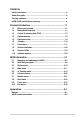
Contents Safety information....................................................................................... iv About this guide.......................................................................................... iv Package contents........................................................................................ vi H97M-PLUS specifications summary........................................................ vi Product introduction..............................................................
Safety information Electrical safety • To prevent electrical shock hazard, disconnect the power cable from the electrical outlet before relocating the system. • When adding or removing devices to or from the system, ensure that the power cables for the devices are unplugged before the signal cables are connected. If possible, disconnect all power cables from the existing system before you add a device.
Where to find more information Refer to the following sources for additional information and for product and software updates. 1. ASUS websites The ASUS website provides updated information on ASUS hardware and software products. Refer to the ASUS contact information. 2. Optional documentation Your product package may include optional documentation, such as warranty flyers, that may have been added by your dealer. These documents are not part of the standard package.
Package contents Check your motherboard package for the following items. Motherboard ASUS H97M-PLUS motherboard Cables 2 x Serial ATA 6.0 Gb/s cables Accessories 1 x I/O Shield Application DVD Support DVD Documentation User Guide If any of the above items is damaged or missing, contact your retailer.
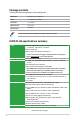
H97M-PLUS specifications summary Storage Intel® H97 Express Chipset with RAID 0, 1, 5, 10 and Intel® Rapid Storage Technology 13 support - 1 x M.2 Socket 3 with M Key, type 2260/2280 storage devices support (both SATA & PCIE mode)* - 6 x SATA 6.0 Gb/s ports (gray) - Supports Intel® Smart Response Technology, Intel® Rapid Start Technology, Intel® Smart Connect Technology** * M.2 Socket 3 shares bandwidth with SATA_5/6, and supports M Key and type 2260/2280 storage devices.
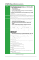
H97M-PLUS specifications summary ASUS exclusive features ASUS EPU - EPU Interactive HomeCloud Media Streamer - Pipe music or movies from your PC to a smart TV - Media Streamer app for portable smartphone/tablet, supporting iOS 7 and Android 4.0 system Gaming Scenario Crystal Sound 2 - Flawless audio that makes you part of the game Steam Support - Compatible with the most fun gaming platform under Windows® system ASUS Exclusive Features - USB 3.
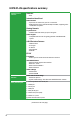
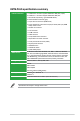
H97M-PLUS specifications summary Internal connectors 1 x USB 3.0/2.0 connector supports additional 2 USB ports (19-pin) 3 x USB 2.0/1.1 connectors support additional 6 USB ports 1 x M.2 Socket 3 (for M Key, type 2260/2280 device) 6 x SATA 6.
x
Product introduction 1.1 Before you proceed 1 Take note of the following precautions before you install motherboard components or change any motherboard settings. 1.2 • Unplug the power cord from the wall socket before touching any component. • Before handling components, use a grounded wrist strap or touch a safely grounded object or a metal object, such as the power supply case, to avoid damaging them due to static electricity.
Place this side towards the rear of the chassis H97M-PLUS 1.2.3 Motherboard layout 1 2 3 4 5 1 6 22.4cm(8.8in) CHA_FAN2 GPU KBMS GPU_LED CPU_FAN BATTERY DIGI +VRM EATX12V DVI_VGA 7 H97M-PLUS SATA6G_2 SATA6G_1 24.4cm(9.6in) EATXPWR 9 SATA6G_34 CHA_FAN1 DRAM_LED USB3_12 AUDIO M.
1.3.4 Layout contents Connectors/Jumpers/Buttons/Slots/LED 1. CPU and chassis fan connectors (4-pin CPU_FAN, 4-pin CHA_FAN1/2) 2. ATX power connectors (24-pin EATXPWR, 8-pin EATX12V) 3. GPU Boost LED 4. GPU Boost switch 5. LGA1150 CPU socket 6. DDR3 DIMM slots 7. USB 3.0 connector (20-1 pin USB3_12) 8. MemOK! switch 9. DRAM LED 10. Intel® H97 Serial ATA 6.0 Gb/s connectors (7-pin SATA6G_1-6) 11. M.2 socket 3 12. Standby power LED (SB_PWR) 13. Clear RTC RAM (3-pin CLRTC) 14.
Unplug all power cables before installing the CPU. 1.3.1 • Upon purchase of the motherboard, ensure that the PnP cap is on the socket and the socket contacts are not bent. Contact your retailer immediately if the PnP cap is missing, or if you see any damage to the PnP cap/socket contacts/motherboard components. ASUS will shoulder the cost of repair only if the damage is shipment/ transit-related. • Ensure that you install the correct CPU designed for LGA1150 only.
4 5 C A B 1.3.2 CPU heatsink and fan assembly installation Apply the Thermal Interface Material to the CPU heatsink and CPU before you install the heatsink and fan if necessary.
3 4 To uninstall the CPU heatsink and fan assembly 2 1 A B B A 1.4 System memory 1.4.1 Overview H97M-PLUS DIMM_B1 DIMM_B2 DIMM_A1 DIMM_A2 This motherboard comes with four Double Data Rate 3 (DDR3) Dual Inline Memory Module (DIMM) sockets.
1.4.2 Memory configurations You may install 2GB, 4GB, and 8GB unbuffered non-ECC DDR3 DIMMs into the DIMM sockets. • You may install varying memory sizes in Channel A and Channel B. The system maps the total size of the lower-sized channel for the dual-channel configuration. Any excess memory from the higher-sized channel is then mapped for single-channel operation. • According to Intel CPU spec, DIMM voltage below 1.65V is recommended to protect the CPU.
1.4.
1.5 Expansion slots In the future, you may need to install expansion cards. The following sub‑sections describe the slots and the expansion cards that they support. Unplug the power cord before adding or removing expansion cards. Failure to do so may cause you physical injury and damage motherboard components. 1.5.1 Installing an expansion card To install an expansion card: 1.
IRQ assignments for this motherboard A B C D E F G H PCIEx16_1 shared – – – – – – – PCIEx16_2 PCI_1 PCI_2 Intel LAN controller shared – shared – – – – – – – – – – – – – – – – – – – – – – – shared EHCI0 EHCI1 HD audio SATA controller 0 SATA controller 1 XHCI I.G.F.X – – shared – – – – shared – – – – – shared – – – – shared – – – – – – – – – – – – – – shared shared – – – – – – – – – – – shared – – – – shared – – – – – – – – – 1.
• If the steps above do not help, remove the onboard battery and move the jumper again to clear the CMOS RTC RAM data. After clearing the CMOS, reinstall the battery. • You do not need to clear the RTC when the system hangs due to overclocking. For system failure due to overclocking, use the CPU Parameter Recall (C.P.R.) feature. Shut down and reboot the system, then the BIOS automatically resets parameter settings to default values. 1.7 Connectors 1.7.
6. Line In port (light blue). This port connects the tape, CD, DVD player, or other audio sources. 7. Line Out port (lime). This port connects a headphone or a speaker. In 4.1-channel, 5.1-channel, and 7.1-channel configurations, the function of this port becomes Front Speaker Out. 8. Microphone port (pink). This port connects a microphone. 9. Side Speaker Out port (gray). This port connects the side speaker in an 7.1-channel audio configuration.
1.7.2 1. Internal connectors Serial port connector (10-1 pin COM) This connector is for a serial (COM) port. Connect the serial port module cable to this connector, then install the module to a slot opening at the back of the system chassis. PIN 1 DCD TXD GND RTS RI RXD DTR DSR CTS COM H97M-PLUS H97M-PLUS Serial port (COM) connector The COM module is purchased separately. 2.
3. Intel® H97 Serial ATA 6.0Gb/s connectors (7-pin SATA6G_1~6) These connectors connect to Serial ATA 6.0 Gb/s hard disk drives via Serial ATA 6.0 Gb/s signal cables. If you installed Serial ATA hard disk drives, you can create a RAID 0, 1, 5, and 10 configuration with the Intel® Rapid Storage Technology through the onboard Intel® H97 chipset.
4. Front panel audio connector (10-1 pin AAFP) NC AGND NC NC SENSE2_RETUR AGND NC SENSE1_RETUR This connector is for a chassis-mounted front panel HD audio I/O module. Connect one end of the front panel audio I/O module cable to this connector. AAFP MIC2 MICPWR Line out_R NC Line out_L H97M-PLUS PORT1 L PORT1 R PORT2 R SENSE_SEND PORT2 L PIN 1 HD-audio-compliant pin definition Legacy AC’97 compliant definition H97M-PLUS Front panel audio connector 5.
6. ATX power connectors (24-pin EATXPWR; 8-pin EATX12V) These connectors are for ATX power supply plugs. The power supply plugs are designed to fit these connectors in only one orientation. Find the proper orientation and push down firmly until the connectors completely fit.
8. USB 2.0 connectors (10-1 pin USB910, USB1112, USB1314) These connectors are for USB 2.0 ports. Connect the USB module cable to any of these connectors, then install the module to a slot opening at the back of the system chassis. These USB connectors comply with USB 2.0 specification that supports up to 480 Mbps connection speed.
10. LPT connector (26-1 pin LPT) The LPT (Line Printing Terminal) connector supports devices such as a printer. LPT standardizes as IEEE 1284, which is the parallel port interface on IBM PC-compatible computers. SLCT PE BUSY ACK# PD7 PD6 PD5 PD4 PD3 PD2 PD1 PD0 STB# LPT PIN 1 GND GND GND GND GND GND GND GND SLIN# INIT# ERR# AFD H97M-PLUS H97M-PLUS Parallel Port Connector 11. SATA M.2 connector This connector is for a SATA M.2-compliant solid-state drive (SSD). The M.
12. System panel connector (20-8 pin PANEL) This connector supports several chassis-mounted functions. SPEAKER +5V Ground Ground Speaker PWR_LED- PWR_LED+ PWR_LED PANEL HDD_LED Reset Ground PWR Ground HDD_LED+ HDD_LED- PIN 1 H97M-PLUS PWR_SW RESET H97M-PLUS System panel connector • System power LED (2-pin PWR_LED) This 2-pin connector is for the system power LED. Connect the chassis power LED cable to this connector.
1.8 Onboard switches Onboard switches allow you to fine-tune performance when working on a bare or open-case system. This is ideal for overclockers and gamers who continually change settings to enhance system performance. MemOK! switch Installing DIMMs that are incompatible with the motherboard may cause system boot failure, and the DRAM_LED near the MemOK! switch lights continuously.
2. GPU Boost switch This switch allows you to enable or disable the GPU Boost function.
1.9 1. Onboard LEDs Standby Power LED The motherboard comes with a standby power LED that lights up to indicate that the system is ON, in sleep mode, or in soft-off mode. This is a reminder that you should shut down the system and unplug the power cable before removing or plugging in any motherboard component. The illustration below shows the location of the onboard LED. H97M-PLUS SB_PWR H97M-PLUS Onboard LED 2. DRAM LED DRAM LED checks the DRAM in sequence during motherboard booting process.
1.10 Software support 1.10.1 Installing an operating system This motherboard supports Windows® 7 (32/64bit), Windows® 8 (32/64bit) and Windows® 8.1 (32/64bit) Operating Systems (OS). Always install the latest OS version and corresponding updates to maximize the features of your hardware. Motherboard settings and hardware options vary. Refer to your OS documentation for detailed information. 1.10.
1-24 Chapter 1: Product introduction
BIOS information 2.1 Managing and updating your BIOS 2 Save a copy of the original motherboard BIOS file to a USB flash disk in case you need to restore the BIOS in the future. Copy the original motherboard BIOS using the ASUS Update utility. 2.1.1 EZ Update EZ Update is a utility that allows you to automatically update your motherboard’s softwares, drivers and the BIOS version easily.
2.1.2 ASUS EZ Flash 2 The ASUS EZ Flash 2 feature allows you to update the BIOS without using an OS‑based utility. Before you start using this utility, download the latest BIOS file from the ASUS website at www.asus.com. To update the BIOS using EZ Flash 2: 1. Insert the USB flash disk that contains the latest BIOS file to the USB port. 2. Enter the Advanced Mode of the BIOS setup program. Go to the Tool menu to select ASUS EZ Flash 2 Utility and press to enable it. 3.
Recovering the BIOS To recover the BIOS: 1. Turn on the system. 2. Insert the support DVD to the optical drive or the USB flash drive that contains the BIOS file to the USB port. 3. The utility automatically checks the devices for the BIOS file. When found, the utility reads the BIOS file and enters ASUS EZ Flash 2 utility automatically. 4. The system requires you to enter BIOS Setup to recover BIOS settings.
Please select boot device: and to move selection ENTER to select boot device ESC to boot using defaults P2: ST3808110AS (76319MB) aigo miniking (250MB) UEFI: (FAT) ASUS DRW-2014L1T(4458MB) P1: ASUS DRW-2014L1T(4458MB) UEFI: (FAT) aigo miniking (250MB) Enter Setup 4. When the booting message appears, press within five (5) seconds to enter FreeDOS prompt. ISOLINUX 3.20 2006-08-26 Copyright (C) 1994-2005 H. Peter Anvin A Bootable DVD/CD is detected. Press ENTER to boot from the DVD/CD.
ASUSTeK BIOS Updater for DOS V1.30 [2014/01/01] Current ROM BOARD: H97M-PLUS VER: 0210 (H :00 B :00) DATE: 03/10/2014 PATH: Update ROM BOARD: Unknown VER: Unknown DATE: Unknown C:\ C: D: FORMAN~1 H97MP.CAP
8390626 2014-03-10 21:14:34 Drives panel Files panel Note [Enter] Select or Load [Up/Down/Home/End] Move [Tab] Switch [Esc] Exit [V] Drive Info 3. Press to switch from Drives panel to Files panel then press keys to select the BIOS file and press .2.2 BIOS setup program Use the BIOS Setup program to update the BIOS or configure its parameters. The BIOS screens include navigation keys and brief online help to guide you in using the BIOS Setup program. Entering BIOS Setup at startup To enter BIOS Setup at startup: • To enter BIOS Setup at startup, press or during the Power-On Self Test (POST). If you do not press or , POST continues with its routines.
Displays the system information, CPU voltage and CPU/ motherboard temperature Sets the system date and time Selects the display language of the BIOS setup program Launches the overclocking (OC) and RAID configuration wizard Sets the system performance mode Selects the boot device priority Selects the boot device priority Displays the CPU/ chassis fan speed Displays the X.M.P.
Quick settings bar Configuration fields Hardware information Menu bar General help Menu items Submenu item Drop-down list Last modified settings Enters EZ mode Scroll bar Quick settings bar The quick settings bar on top of the screen has the following main items: For setting the system date and time For setting the system language For saving the frequently-used system settings and configuration For taking notes For displaying the navigation shortcuts For changing the fan speed settings For configu
Menu items The highlighted item on the menu bar displays the specific items for that menu. For example, selecting Main shows the Main menu items. The other items (Ai Tweaker, Advanced, Monitor, Boot, Tool, and Exit) on the menu bar have their respective menu items. Submenu items A greater than sign (>) before each item on any menu screen means that the item has a submenu. To display the submenu, select the item and press .
This button above the menu bar contains the navigation keys for the BIOS setup program. Use the navigation keys to select items in the menu and change the settings. Last Modified button This button shows the items that you last modified and save in BIOS Setup. Hardware Monitor At the right side of the menu screen is a brief description of system hardware monitor information. 2.3 My Favorites MyFavorites is your personal space where you can easily save and access your favorite BIOS items.
2.4 Main menu The Main menu screen appears when you enter the Advanced Mode of the BIOS Setup program. The Main menu provides you an overview of the basic system information, and allows you to set the system date, time, language, and security settings. 2.4.1 System Language [English] Allows you to choose the BIOS language version from the options. Configuration options: [Español] [Русский] [한국어] [English] 2.4.2 Access Level [Administrator] Displays the current user’s access level. 2.4.
Administrator Password If you have set an administrator password, we recommend that you enter the administrator password for accessing the system. Otherwise, you might be able to see or change only selected fields in the BIOS setup program. To set an administrator password: 1. Select the Administrator Password item and press . 2. From the Create New Password box, key in a password, then press . 3. Confirm the password when prompted. To change an administrator password: 1.
2.5 Ai Tweaker menu The Ai Tweaker menu items allow you to configure overclocking-related items. Be cautious when changing the settings of the Ai Tweaker menu items. Incorrect field values can cause the system to malfunction. The configuration options for this section vary depending on the CPU and DIMM model you installed on the motherboard.
Target CPU Turbo-Mode Frequency: xxxxMHz Displays the target CPU Turbo-Mode frequency. Target DRAM Frequency: xxxxMHz Displays the target DRAM frequency. Target Cache Frequency: xxxxMHz Displays the target Cache frequency. Target DMI/PEG Frequency: xxxxMHz Displays the target DMI/PEG frequency. Target CPU Graphics Frequency: xxxxMHz Displays the target iGPU frequency. 2.5.1 CPU Core Ratio [Auto] Allows you to set the CPU core ratio automatically or manually.
2.5.3 Max. CPU Cache Ratio [Auto] Allows you to set the uncore ratio of the processor to its possible maximum value. Use <+>/<> to adjust the value. The values depend on the CPU installed. 2.5.4 CPU Ratio Tuner [Auto] This item allows you to enable or disable the CPU ratio tuner. Enabling this item may enhance the overclocking capability of non-K series CPUs. Configuration options: [Auto] [Enabled] [Disable] 2.5.
2.5.11 DIGI+ VRM CPU Load-Line Calibration [Auto] Load-line is defined by Intel VRM specification and affects the CPU power voltage. The CPU working voltage will decrease proportionally depending on the CPU loading. Higher levels of the load-line calibration can get a higher voltage and a better overclocking performance but increases the CPU and VRM thermal. Configuration options: [Auto] [Regular] [Medium] [High] [Ultra High] [Extreme] The boosted performance may vary depending on the CPU specification.
2.5.12 Internal CPU Power Management The subitems in this menu allow you to set the CPU ratio and features. Enhanced Intel® SpeedStep Technology [Enabled] Allows you to enable or disable the Enhanced Intel® SpeedStep Technology (EIST). [Disabled] Disables this function. [Enabled] The operating system dynamically adjusts the processor voltage and core frequency which may result in decreased average consumption and decreased average heat production.
CPU Internal Power Configuration CPU Integrated VR Efficiency Management [Auto] Allows you to manage the CPU integrated VR efficiency. Configuration options: [Auto] [High Performance] [Balanced] Power Decay Mode [Auto] Enable to improve power saving on the Fully Integrated Voltage Regulator as the processor enters low current mode. Configuration options: [Auto] [Disabled] [Enabled] Idle Power-in Response [Auto] Allows you to set the idle power-in response.
2.5.14 CPU Core Voltage [Auto] This item allows you to set the CPU Core voltage. Increase the core voltage when increasing the ring frequency. Configuration options: [Auto] [Manual Mode] [Offset Mode]. CPU Core Voltage Override [Auto] This item appears only when you set the CPU Core Voltage to [Manual Mode] and allows you to set the CPU Core voltage override. The values range from 0.001V to 1.920V with a 0.001V interval.
Offset Mode Sign [+] This item appears only when you set the CPU Graphics Voltage to [Offset Mode] or [Adaptive Mode] and allows you to set the offset mode sign. Configuration options: [+] [-] CPU Graphics Voltage Offset [Auto] This item appears only when you set the CPU Graphics Voltage to [Offset Mode] or [Adaptive Mode] and allows you to set the CPU graphics voltage offset. The values range from 0.001V to 0.999V with a 0.001V interval.
SVID Voltage Override [Auto] This item allows you to set the SVID Voltage override. By default, this item takes the standard value of the installed CPU. You can use the <+> or <-> keys to adjust the value. The values range from 0.001V to 2.440 V with a 0.001 V interval. 2.5.21 CPU Input Voltage (VCCIN) [Auto] This item allows you to set an input voltage for the CPU by the external voltage regulator. By default, this item takes the standard value of the installed CPU.
2.6 Advanced menu The Advanced menu items allow you to change the settings for the CPU and other system devices. Be cautious when changing the settings of the Advanced menu items. Incorrect field values can cause the system to malfunction. 2.6.1 CPU Configuration The items in this menu show the CPU-related information that the BIOS automatically detects. The items shown in submenu may be different due to the CPU you installed.
Active Processor Cores [All] Allows you to choose the number of CPU cores to activate in each processor package. Configuration options: [All] [1] [2] [3]. Limit CPUID Maximum [Disabled] [Enabled] Allows legacy operating systems to boot even without support for CPUs with extended CPUID functions. [Disabled] Disables this function. Execute Disable Bit [Enabled] [Enabled] Enables the No-Execution Page Protection Technology. [Disabled] Forces the XD feature flag to always return to zero (0).
CPU C states [Auto] [Auto] Automatic configuration. [Enabled] Enables the CPU C states. [Disabled] Disables the CPU C states.. The following items appear only when you set the CPU C states to [Enabled]. Enhanced C1 state [Enabled] [Enabled] Enables enhanced C1 state. [Disabled] Disables enhanced C1 state. CPU C3 Report [Enabled] Allows you to disable or enable the CPU C3 report to OS.
Entry After [x] Allows you to set the wake-up time. The values range from 0 (immediately) to 120. Active Page Threshold Support [Enabled] The system automatically set itself to sleep when the partition size is not enough for Rapid Start Technology to work. Configuration options: [Enabled] [Disabled] Active Memory Threshold [0] Key in the value for the additional partition size for Rapid Start Technology to work. Ensure that the caching partition size is larger than the total memory size.
[RAID] Set to [RAID Mode] when you want to create a RAID configuration from the SATA hard disk drives. Aggressive LPM Support [Disabled] This item appears only when you set SATA Mode Selection to [AHCI] and allows you to enable or disable PCH entering link power state aggressively. Configuration options: [Disabled] [Enabled] S.M.A.R.T. Status Check [On] S.M.A.R.T. (Self-Monitoring, Analysis and Reporting Technology) is a monitor system.
DMI Configuration Allows you to control various DMI functions. DMI Gen 2 [Enabled] Allows you to enable or disable DMI Gen 2. Configuration options: [Enabled] [Disabled] NB PCI-E Configuration Allows you to configure the NB PCI Express settings. PCIEx16_1 Link Speed [Auto] Allows you to configure the PCIEx16 speed for slot 1. Configuration options: [Auto] [Gen1] [Gen2] [Gen3] Memory Configuration Allows you to configure the memory configuration parameters.
USB Single Port Control USB3_1~6 [Enabled] Allows you to enable or disable an individual USB port. Refer to the section 1.2.3 Motherboard layout in this user manual for the locations of the USB ports. Configuration options: [Enabled] [Disabled]. USB 7~14 [Enabled] Allows you to enable or disable an individual USB port. Refer to the section 1.2.3 Motherboard layout in this user manual for the locations of the USB ports. Configuration options: [Enabled] [Disabled]. 2.6.
Front Panel Type [HD Audio] Allows you to set the front panel audio connector (AAFP) mode to legacy AC’97 or high-definition audio depending on the audio standard that the front panel audio module supports. [HD Audio] Sets the front panel audio connector (AAFP) mode to high definition audio. [AC97] Sets the front panel audio connector (AAFP) mode to legacy AC’97 SPDIF Out Type [SPDIF] [SPDIF] Sets to an SPDIF audio output. [HDMI] Sets to an HDMI audio output.
Change Settings [Auto] Allows you to select an optimal setting for Super I/O devices. Configuration options: [Auto] [IO=378h; IRQ=5;] [IO=378h; IRQ=5,6,7,9,10,11,12;] [IO=278h; IRQ=5,6,7,9,10,11,12;] [IO=3BCh; IRQ=5,6,7,9,10,11,12;] Device Mode [STD Printer Mode] Allows you to change the printer port mode. Configuration options: [STD Printer Mode] [SPP Mode] [EPP-1.9 and SPP Mode] [EPP-1.7 and SPP Mode] [ECP Mode] [ECP and EPP 1.9 Mode] [ECP and EPP 1.7 Mode] 2.6.
Power On By RTC [Disabled] [Disabled] Disables RTC to generate a wake event. [Enabled] When set to [Enabled], the items RTC Alarm Date (Days) and Hour/ Minute/Second will become user-configurable with set values. 2.6.9 Network Stack Configuration Network Stack [Disabled] This item allows user to disable or enable the UEFI network stack. Configuration options: [Disabled] [Enabled] The following two items appear only when you set the previous item to [Enabled].
Scroll down to display the following items: 2.7.1 QFan Tuning Click this item to automatically detect the lowest speed and configure the minimum duty cycle for each fan. 2.7.2 CPU / MB Temperature [xxxºC/xxxºF] The onboard hardware monitor automatically detects and displays the CPU / motherboard temperature. 2.7.
2.7.5 CPU Q-Fan Control [Enabled] [Disabled] Disables the CPU Q-Fan control feature. [Enabled] Enables the CPU Q-Fan control feature. CPU Fan Speed Low Limit [200 RPM] This item appears only when you enable the CPU Q-Fan Control feature and allows you to disable or set the CPU fan warning speed.
2.7.6 Chassis Fan 1/2 Q-Fan Control [DC Mode] [Disabled] Disables the Chassis Q-Fan control feature. [PWM Mode] Enables DC mode Q-Fan control for a 4-pin chassis fan. [DC Mode] Enables the Chassis Q-Fan control feature for a 3-pin chassis fan. Chassis Fan 1/2 Q-Fan Source [CPU] The assigned fan will be controlled according to the selected temperature source.
Chassis Fan 1/2 Min. Duty Cycle(%) [60] Use the <+> and <-> keys to adjust the minimum chassis fan duty cycle. The values range from 60% to 100%. When the chassis temperature is under 40ºC, the chassis fan will operate at the minimum duty cycle. 2.7.7 Allow Fan Stop [Disabled] This item allows the fan to run at 0% duty cycle when the temperature drops below the lower temperature. Configuration options: [Disabled] [Enabled] 2.7.
2.8.1 Fast Boot [Enabled] [Enabled] Select to accelerate the boot speed. [Disabled] Select to go back to normal boot. The following five items appear when you set Fast Boot to [Enabled]. SATA Support [All Devices] [All Devices] All devices connected to SATA ports will be available during POST. This process will extend the POST time. [Hard Drive Only] Only hard drives connected to SATA ports will be detected during POST. Any hardware change will disable fast boot.
2.8.2 Boot Logo Display [Auto] [Auto] Adjusts the logo size automatically based on Windows® display requirements. [Full Screen] Maximize the boot logo size. [Disabled] Hide the logo during POST. POST Delay Time [3 sec] This item appears only when you set Boot Logo Display to [Enabled]. This item allows you to select the desired additional POST waiting time to easily enter the BIOS setup. You can only execute the POST delay time during Normal Boot. The values range from 0 to 10 seconds.
2.8.9 CSM (Compatibility Support Module) Allows you to configure the CSM (Compatibility Support Module) items to fully support the various VGA, bootable devices and add-on devices for better compatibility. Launch CSM [Enabled] [Auto] The system automatically detects the bootable devices and the add-on devices. [Enabled] For better compatibility, enable the CSM to fully support the non-UEFI driver add-on devices or the Windows® UEFI mode.
Install Default Secure Boot keys Allows you to immediately load the default Security Boot keys, Platform key (PK), Key-exchange Key (KEK), Signature database (db), and Revoked Signatures (dbx). The Platform Key (PK) state will change from Unloaded mode to Loaded mode. The settings are applied after reboot or at the next reboot. Key-exchange Key (KEK) refers to Microsoft® Secure Boot Key database (KEK). Clear Secure Boot keys This item appears only when you load the default Secure Boot keys.
DB Management The db (Authorized Signature database) lists the signers or images of UEFI applications, operating system loaders, and UEFI drivers that you can load on the single computer. Delete the db Allows you to delete the db file from your system. Configuration options: [Yes] [No] Load Default db Select Yes to load the system default db (signature database) or select No to load a downloaded db from a USB storage device.
2.9 Tools menu The Tools menu items allow you to configure options for special functions. Select an item then press to display the submenu. 2.9.1 ASUS EZ Flash 2 Utility Allows you to run ASUS EZ Flash 2. Press [Enter] to launch the ASUS EZ Flash 2 screen. For more details, see section 2.1.2 ASUS EZ Flash 2. 2.9.2 Setup Animator [Enabled] Enables or disables Setup Animator. Configuration options: [Disabled] [Enabled] 2.9.
2.10 Exit menu The Exit menu items allow you to load the optimal default values for the BIOS items, and save or discard your changes to the BIOS items. Load Optimized Defaults This option allows you to load the default values for each of the parameters on the Setup menus. When you select this option or if you press , a confirmation window appears. Select Yes to load the default values.
Appendices Notices Federal Communications Commission Statement This device complies with Part 15 of the FCC Rules. Operation is subject to the following two conditions: • This device may not cause harmful interference. This device must accept any interference received including interference that may cause undesired operation. This equipment has been tested and found to comply with the limits for a Class B digital device, pursuant to Part 15 of the FCC Rules.
Canadian Department of Communications Statement This digital apparatus does not exceed the Class B limits for radio noise emissions from digital apparatus set out in the Radio Interference Regulations of the Canadian Department of Communications. This class B digital apparatus complies with Canadian ICES-003. VCCI: Japan Compliance Statement VCCI Class B Statement This is a Class B product based on the standard of the VCCI Council.
ASUS contact information ASUSTeK COMPUTER INC. Address 15 Li-Te Road, Peitou, Taipei, Taiwan 11259 Telephone +886-2-2894-3447 Fax +886-2-2890-7798 E-mail info@asus.com.tw Web site www.asus.com.com/ Technical Support Telephone Fax Online support +86-21-38429911 +86-21-5866-8722, ext. 9101# http://www.asus.com/tw/support/ ASUS COMPUTER INTERNATIONAL (America) Address 800 Corporate Way, Fremont, CA 94539, USA Telephone +1-510-739-3777 Fax +1-510-608-4555 Web site http://www.
A-4 Appendices (510)739-3777/(510)608-4555 800 Corporate Way, Fremont, CA 94539. Asus Computer International Date : Signature : Representative Person’s Name : Apr. 14, 2014 Steve Chang / President This device complies with part 15 of the FCC Rules. Operation is subject to the following two conditions: (1) This device may not cause harmful interference, and (2) this device must accept any interference received, including interference that may cause undesired operation.