Motherboard X99-PRO
E9707 First Edition September 2014 Copyright© 2014 ASUSTeK COMPUTER INC. All Rights Reserved. No part of this manual, including the products and software described in it, may be reproduced, transmitted, transcribed, stored in a retrieval system, or translated into any language in any form or by any means, except documentation kept by the purchaser for backup purposes, without the express written permission of ASUSTeK COMPUTER INC. (“ASUS”).
Contents Safety information........................................................................................................ v About this guide.......................................................................................................... vi X99-PRO specifications summary........................................................................... viii Package contents......................................................................................................
Chapter 3: 3.1 3.2 BIOS setup Knowing BIOS............................................................................................. 3-1 BIOS setup program................................................................................... 3-2 3.2.1 EZ Mode...................................................................................... 3-3 3.2.2 Advanced Mode........................................................................... 3-4 3.2.3 QFan Control................................
Safety information Electrical safety • To prevent electrical shock hazard, disconnect the power cable from the electrical outlet before relocating the system. • When adding or removing devices to or from the system, ensure that the power cables for the devices are unplugged before the signal cables are connected. If possible, disconnect all power cables from the existing system before you add a device.
About this guide This user guide contains the information you need when installing and configuring the motherboard. How this guide is organized This guide contains the following parts: 1. Chapter 1: Product introduction This chapter describes the features of the motherboard and the new technology it supports. It includes description of the switches, jumpers, and connectors on the motherboard. 2.
Conventions used in this guide To ensure that you perform certain tasks properly, take note of the following symbols used throughout this manual. DANGER/WARNING: Information to prevent injury to yourself when trying to complete a task. CAUTION: Information to prevent damage to the components when trying to complete a task IMPORTANT: Instructions that you MUST follow to complete a task. NOTE: Tips and additional information to help you complete a task.
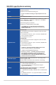
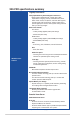
X99-PRO specifications summary LGA2011-v3 socket for the New Intel® Core™ i7 processors Supports 22nm CPU CPU Supports Intel® Turbo Boost Technology 2.0* * The Intel® Turbo Boost Technology 2.0 support depends on the CPU types. Chipset Intel® X99 Express Chipset 8 x DIMM DDR4 max at 64 GB 3300 (O.C.)* / 3200 (O.C.)* / 3000 (O.C.)* / 2800 (O.C.)* / 2666 (O.C.)* / 2400 (O.C.
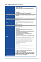
X99-PRO specifications summary - Supports Intel® Smart Response Technology, Intel® Rapid Recovery Technology*** * Type 2230 storage device is only available on ASUS HYPER M.2x 4 card Storage ** 1 at onboard, 1 at bundled add-on card (ASUS HYPER M.2x4 card) *** Due to chipset behavior, the SATA6G_78 and SATA6G_910 ports (black) do not support Intel® Rapid Storage Technology including RAID configuration. ****These functions work depending on the CPU installed. Wi-Fi - Speedy Wi-Fi 802.
X99-PRO specifications summary Flagship Performance 5-Way Optimization by Dual Intelligent Processors 5 - Whole system optimization with a single click! 5-Way Optimization tuning key perfectly consolidates TPU, EPU, DIGI+ Power Control, Fan Xpert 3, and Turbo APP together, providing better CPU performance, efficient power saving, precise digital power control, whole system cooling and even tailor your own app usages.
X99-PRO specifications summary Media Streamer - Pipe music or movies from your PC to a smart TV, your entertainment goes wherever you go! - Media Streamer app for portable smartphone/tablet, supporting iOS 7 and Android™ 4.0 systems NFC Express 2 support (optional) - NFC Receiver and 2-port USB 3.
X99-PRO specifications summary - ASUS Stainless Steel rear I/O - 3x more durable corrosionresistant coating USB 3.0 Boost USB Charger+ ASUS Special Features Ai Charger+ Disk Unlocker Ai Suite 3 MemOK! EZ XMP Quiet Thermal Design ASUS Quiet Thermal Solution - ASUS Fan Xpert 3 - ASUS Fanless Design: Heatsink solution with the aesthetic streamline I/O cover Precision Tweaker 2 ASUS Exclusive Overclocking Features - vCore: Adjustable CPU Core voltage at 0.
X99-PRO specifications summary 1 x 4-pin CPU OPT Fan connector 4 x 4-pin Chassis Fan connectors for both 3-pin (DC Mode) and 4-pin (PWM Mode) coolers control 1 x Front panel audio connector(AAFP) 1 x S/PDIF Out header 1 x 5-pin Thunderbolt header for ASUS ThunderboltEX series support 1 x TPM connector 1 x Serial port (COM) header 1 x 24-pin EATX Power connector 1 x 8-pin EATX 12V Power connector Internal I/O Connectors 1 x System Panel (Q-Connector) 1 x 5-pin Extension fan (EXT_FAN) connector 1 x 3-pin Cha
Package contents Check your motherboard package for the following items 6 x Serial ATA 6 Gb/s cables ASUS X99-PRO motherboard 1 x ASUS SLI™ bridge connector 1 x ASUS Q-Shield HYPER M.2 x 4 Support DVD 1 x ASUS 2T2R dual-band Wi-Fi moving antennas (Wi-Fi 802.11a/b/g/n/ac compliant) nual User Ma 1 x 2-in-1 ASUS Q-Connector kit Technical documentations xiv • If any of the above items is damaged or missing, contact your retailer. • The illustrated items above are for reference only.
Installation tools and components Intel® LGA2011-v3 CPU Intel® LGA2011-v3 compatible CPU Fan PC chassis SATA hard disk drive Philips (cross) screwdriver DIMM 1 bag of screws Power supply unit SATA optical disc drive (optional) Graphics card The tools and components in the table above are not included in the motherboard package.
xvi
Chapter 1: Product Introduction Product introduction 1.1 Special features 1.1.1 Product highlights 1 LGA2011-v3 socket for Intel® Core™ i7 processors This motherboard supports the New Intel® Core™ i7 processors in the LGA2011-v3 package. It provides great system performance, quad-channel DDR4 memory slots and PCI Express 2.0/3.0 expansion slots. Intel® X99 Express Chipset Intel® X99 Express Chipset is a single chipset that supports the LGA2011-v3 socket for Intel® Core™ i7 processors.
Complete USB 3.0 integration This motherboard offers you the strategic USB 3.0 accessibility for both the front and rear panels, allowing you to experience the convenience of the latest plug and play connectivity solution at speed up to ten times faster than USB 2.0. 1.1.
1.2 Motherboard overview 1.2.1 Before you proceed Take note of the following precautions before you install motherboard components or change any motherboard settings. Unplug the power cord from the wall socket before touching any component. • Before handling components, use a grounded wrist strap or touch a safely grounded object or a metal object, such as the power supply case, to avoid damaging them due to static electricity. • Hold components by the edges to avoid touching the ICs on them.
1.2.2 Motherboard layout Chapter 1 Refer to 1.2.9 Internal connectors and 2.3.1 Rear I/O connection for more information about rear panel connectors and internal connectors.
Layout contents Page 1-7 1-33 1-6 1-34 1-17 1-29 1-31 1-19 1-30 1-18 1-37 1-38 1-35 1-36 1-32 1-20 1-21 1-36 1-25 1-16 1-16 1-38 1-39 1-30 1-22 1-37 Chapter 1 Connectors/Jumpers/Buttons and switches/Slots 1. DDR4 DIMM slots 2. CPU, CPU optional, extension, and chassis fan connectors (4-pin CPU_FAN, 4-pin CPU_OPT, 5-pin EXT_FAN, 4-pin CHA_FAN1-4 ) 3. LGA2011-v3 CPU socket 4. ATX power connectors (24-pin EATXPWR; 8-pin EATX12V) 5. MemOK! button 6.
1.2.3 Central Processing Unit (CPU) The motherboard comes with a surface mount LGA2011-v3 socket designed for Intel® Core™ i7 processors. • Ensure that all power cables are unplugged before installing the CPU. • Upon purchase of the motherboard, ensure that the PnP cap is on the socket and the socket contacts are not bent. Contact your retailer immediately if the PnP cap is missing, or if you see any damage to the PnP cap/socket contacts/motherboard components.
1.2.4 System memory The motherboard comes with eight DDR 4 (Double Data Rate 4) Quad Inline Memory Modules (DIMM) slots. A DDR4 module is notched differently from a DDR, DDR2, or DDR3 module. DO NOT install a DDR, DDR2, or DDR3 memory module to the DDR4 slot.
Memory configurations You may install 2 GB, 4 GB and 8 GB unbuffered and non‑ECC DDR4 DIMMs into the DIMM sockets. • You may install varying memory sizes in Channel A, Channel B, Channel C, and Channel D. The system maps the total size of the lower-sized channel for the dualchannel configuration. Any excess memory from the higher-sized channel is then mapped for single-channel operation. • According to Intel® CPU spec, DIMM voltage below 1.65 V is recommended to protect the CPU.
X99-PRO Motherboard Qualified Vendors Lists (QVL) DDR4 3000 (O.C.) MHz capability Vendors Part No. Size SS/ DS Chip Brand Chip NO. Timing Voltage DIMM socket support (Optional) 2 4 G.SKILL F4-3000C16Q-32GRR 32GB (8GBx4) DS Hynix H5AN4G8NMFR 16-16-16-36 1.35V • • G.SKILL F4-3000C15Q-16GRR 16GB (4GBx4) SS Hynix H5AN4G8NMFR 15-15-15-35 1.35V • • G.SKILL F4-3000C15Q2-32GRR 32GB (4GBx8) SS Hynix H5AN4G8NMFR 15-15-15-35 1.
DDR4 2400 (O.C.) MHz capability Vendors Part No. Size SS/ DS Chip Brand Chip NO. Timing Voltage DIMM socket support (Optional) 2 4 A_DATA AX4U2400W8G16-DRZ 8GB SS SK hynix H5AN4G 8NMFR 16-16-16-39 1.2V • • CORSAIR CMD16GX4M4A2400C14 16GB (4GBx4) SS - - 14-16-16-31 1.2V • • CORSAIR CMD32GX4M4A2400C14 32GB (8GBx4) DS - - 14-16-16-31 1.2V • • CORSAIR CMD64GX4M8A2400C14 64GB (8GBx8) DS - - 14-16-16-31 1.
DDR4 2133 (O.C.) MHz capability Part No. Size SS/ DS Chip Brand Chip NO. Timing Voltage 2 4 6 8 Micron MTA8ATF51264AZ-2G1A1 4GB SS Micron D9RGQ 15-1515-37 1.2V • • • • Micron MTA16ATF1G64AZ-2G1A1 8GB DS Micron D9RGQ 15-1515-37 1.2V • • • • Crucial CT4G4DFS8213.8FA1 4GB SS Micron D9RGQ 15-1515-37 1.2V • • • • Crucial CT8G4DFD8213.16FA1 8GB DS Micron D9RGQ 15-1515-37 1.
• Side(s): SS - Single-sided DS - Double-sided DIMM support: Supports one (1) module inserted into any slot as Single-channel memory configuration. We suggest that you install the module into D1 slot. Supports two (2) modules inserted into one pair of the dark gray slots as one pair of dual-channel memory configuration. We suggest that you install the modules into slots B1 and D1 for better compatibility.
1.2.5 Expansion slots Unplug the power cord before adding or removing expansion cards. Failure to do so may cause you physical injury and damage motherboard components. Slot Description 40-LANE 28-LANE 1 PCIe 3.0/2.0 x16_1 slot PCIe 3.0/2.0 x16_1 slot 2 PCIe 2.0 x1_1 slot PCIe 2.0 x1_1 slot 3 PCIe 2.0 x16_2 slot PCIe 2.0 x16_2 slot 4 PCIe 3.0/2.0 x16_3 slot PCIe 3.0/2.0 x16_3 slot 5 PCIe 2.0 x1_2 slot PCIe 2.0 x1_2 slot 6 PCIe 3.0/2.0 x16_4 slot PCIe 3.0/2.
40-LANE CPU PCI Express 3.0 operating mode VGA configuration PCIe 3.0/2.0 x16_1 PCIe 3.0/2.0 x16_3 PCIe 3.0/2.0 x16_4 x16 (single VGA recommended) N/A N/A Dual VGA/PCIe cards x16 x16 N/A Triple VGA/ PCIe cards x16 x16 x8* Single VGA/ PCIe card * When the M.2 x4 slot is occupied, the PCIe x16_4 slot will be disabled. 28-LANE CPU PCI Express 3.0 operating mode VGA configuration PCIe 3.0/2.0 x16_1 PCIe 3.0/2.0 x16_3 PCIe 3.0/2.
IRQ assignments for this motherboard PCIe x16_1 A B C D E F G H shared – – – – – – – PCIe x1_1 – – shared – – – – – PCIe x16_2 – – – shared* – – – – PCIe x16_3 shared – – – – – – – PCIe x1_2 – – – shared – – – – PCIe x16_4 shared – – – – – – – SMBUS Controller – – shared – – – – – Wi-Fi/Bluetooth 4.
1.2.6 Onboard buttons and switches Onboard buttons and switches allow you to fine-tune performance when working on a bare or open-case system. This is ideal for overclockers and gamers who continually change settings to enhance system performance. 1. Power-on button The motherboard comes with a power-on button that allows you to power up or wake up the system.
3. MemOK! button • Refer to section 1.2.8 Onboard LEDs for the exact location of the DIAG_DRAM LED. • The DIAG_DRAM LED also lights up when the DIMM is not properly installed. Turn off the system and reinstall the DIMM before using the MemOK! function. • The MemOK! button does not function under Windows® OS environment. • During the tuning process, the system loads and tests failsafe memory settings. It takes about 30 seconds for the system to test one set of failsafe settings.
4. TPU switch With its two-level adjustment functions, the TPU allows you to automatically adjusts the CPU ratio and clock speed for an optimal system performance. • Enable this switch when the system is powered off. • When the TPU switch is set to Enabled (TPU_I: CPU Ratio Boost), the system automatically adjusts the CPU ratio for an enhanced performance.
5. EPU switch Enable this switch to automatically detect the current PC loadings and intelligently moderate the power consumption. Enable this switch when the system is powered off. The EPU LED (O2LED3) near the EPU switch lights up when you enable the EPU switch. Refer to section 1.2.8 Onboard LEDs for the exact location of the EPU LED. • If you enable this switch under Windows® OS environment, the EPU function will be activated after the next system bootup.
6. EZ XMP switch Enable this switch to overclock the installed DIMMs, allowing you to enhance the DIMM’s speed and performance. The EZ XMP LED (XLED1) lights up when you enable the EZ XMP switch. For the location of the EZ XMP LED, refer to section 1.2.8 Onboard LEDs.
1.2.7 Jumpers 1. Clear RTC RAM jumper (3-pin CLRTC) This jumper allows you to clear the Real Time Clock (RTC) RAM in CMOS. You can clear the CMOS memory of date, time, and system setup parameters by erasing the CMOS RTC RAM data. The onboard button cell battery powers the RAM data in CMOS, which include system setup information such as system passwords. To erase the RTC RAM: 1. Turn OFF the computer and unplug the power cord. 2. Move the jumper cap from pins 1-2 (default) to pins 2-3.
2. CPU Over Voltage jumper (3-pin CPU_OV) The CPU Over Voltage jumper allows you to set a higher CPU voltage for a flexible overclocking system, depending on the type of the installed CPU. To gain more CPU voltage setting, insert the jumper to pins 2-3. To go back to its default CPU voltage setting, insert the jumper to pins 1-2.
1.2.8 1. Onboard LEDs POST State LEDs The POST State LEDs provide the status of these key components during POST (Power-On-Self Test): CPU, memory modules, VGA card, and hard disk drives. If an error is found, the critical component’s LED stays lit up until the problem is solved. 2. TPU LED (TPU_LED) Chapter 1 The TPU LED lights up when the TPU switch is enabled.
3. EPU LED (O2LED3) The EPU LED lights up when the EPU switch is enabled. 4. EZ XMP LED (XLED) This LED lights up when you enable the EZ XMP switch.
5. Q-Code LEDs The Q-Code LED design provides you with a 2-digit error code that displays the system status. Refer to the Q-Code table on the next page for details.
Code 00 02 03 04 06 10 11 – 14 15 – 18 19 – 1C 2B – 2F 30 31 32 – 36 37 – 3A 3B – 3E 4F 50 – 53 Chapter 1 F3 F4 F5 – F7 F8 F9 FA FB – FF 60 61 62 63 – 67 68 69 6A 6B – 6F 70 71 72 73 – 77 78 79 7A – 7F 90 91 92 93 Description Not used microcode CACHE_ENABLED PCH initialization CPU_EARLY_INIT PEI Core is started Pre-memory CPU initialization is started Pre-memory System Agent initialization is started Pre-memory PCH initialization is started Memory initialization Reserved for ASL (see ASL Status Codes sec
Description PCI Bus Enumeration PCI Bus Request Resources PCI Bus Assign Resources Console Output devices connect Console input devices connect Super IO Initialization USB initialization is started USB Reset USB Detect USB Enable Reserved for future AMI codes IDE initialization is started IDE Reset IDE Detect IDE Enable SCSI initialization is started SCSI Reset SCSI Detect SCSI Enable Setup Verifying Password Start of Setup Reserved for ASL (see ASL Status Codes section below) Setup Input Wait Reserved for
Code D6 D7 D8 D9 DA DB DC Description No Console Output Devices are found No Console Input Devices are found Invalid password Error loading Boot Option (LoadImage returned error) Boot Option is failed (StartImage returned error) Flash update is failed Reset protocol is not available ACPI/ASL Checkpoints (under OS) Code 03 04 05 30 40 AC AA Description System is entering S3 sleep state System is entering S4 sleep state System is entering S5 sleep state System is waking up from the S3 sleep state System is
1.2.9 Internal connectors 1. Intel® X99 Serial ATA 6 Gb/s connectors (7-pin SATA6G_12, SATA6G_34, SATA6G_5, SATA6G_6/SATAEXPRESS, SATA6G_78, SATA6G_910) These connectors connect to Serial ATA 6 Gb/s hard disk drives via Serial ATA 6 Gb/s signal cables. • These connectors are set to [AHCI Mode] by default. If you intend to create a Serial ATA RAID set using these connectors, set the SATA Mode item in the BIOS to [RAID Mode]. Refer to section 3.6.3 PCH Storage Configuration for details.
2. Digital audio connector (4-1 pin SPDIF_OUT) This connector is for an additional Sony/Philips Digital Interface (S/PDIF) port. Connect the S/PDIF Out module cable to this connector, then install the module to a slot opening at the back of the system chassis. The S/PDIF module is purchased separately. 3. M.2 socket 3 This socket allows you to install an M.2 (NGFF) SSD module. Chapter 1 This socket supports M Key and type 2242/2260/2280/22110 storage devices.
4. USB 3.0 connectors (20-1 pin USB3_12, USB3_34) These connectors allow you to connect a USB 3.0 module for additional USB 3.0 front or rear panel ports. With an installed USB 3.0 module, you can enjoy all the benefits of USB 3.0 including faster data transfer speeds of up to 5 Gb/s, faster charging time for USB-chargeable devices, optimized power efficiency, and backward compatibility with USB 2.0. The USB 3.0 module is purchased separately. Ensure to install the related driver to fully use the USB 3.
5. USB 2.0 connectors (10-1 pin USB1112; US1314) These connectors are for USB 2.0 ports. Connect the USB module cable to any of these connectors, then install the module to a slot opening at the back of the system chassis. These USB connectors comply with USB 2.0 specification that supports up to 48 Mb/s connection speed. DO NOT connect a 1394 cable to the USB connectors.
6. CPU, CPU optional, extension, and chassis fan connectors (4-pin CPU_FAN; 4-pin CPU_OPT; 5-pin EXT_FAN, 4-pin CHA_FAN1-4) • DO NOT forget to connect the fan cables to the fan connectors. Insufficient air flow inside the system may damage the motherboard components. These are not jumpers! Do not place jumper caps on the fan connectors! • Ensure that the CPU fan cable is securely installed to the CPU fan connector. • The CPU_FAN connector supports the CPU fan of maximum 1A (12 W) fan power.
7. ATX power connectors (24-pin EATXPWR; 8-pin EATX12V) These connectors are for ATX power supply plugs. The power supply plugs are designed to fit these connectors in only one orientation. Find the proper orientation and push down firmly until the connectors completely fit. • For a fully configured system, we recommend that you use a power supply unit (PSU) that complies with ATX 12 V Specification 2.0 (or later version) and provides a minimum power of 350 W.
8. System panel connector (20-8 pin PANEL) This connector supports several chassis-mounted functions. • System power LED (2-pin PLED) This 2-pin connector is for the system power LED. Connect the chassis power LED cable to this connector. The system power LED lights up when you turn on the system power, and blinks when the system is in sleep mode. • Hard disk drive activity LED (2-pin HDD_LED) This 2-pin connector is for the HDD Activity LED. Connect the HDD Activity LED cable to this connector.
9. TPM connector (20-1 pin TPM) This connector supports a Trusted Platform Module (TPM) system, which securely store keys, digital certificates, passwords and data. A TPM system also helps enhance network security, protect digital identities, and ensures platform integrity. The TPM module is purchased separately. 10. DirectKey connector (2-pin DRCT) This connector is for the chassis-mounted button that supports the DirectKey function.
11. Thunderbolt header (5-pin TB_HEADER) This connector is for the add-on Thunderbolt I/O card that supports Intel’s Thunderbolt Technology, allowing you to connect up to six Thunderbolt-enabled devices and a DisplayPort-enabled display in a daisy-chain configuration. The add-on Thunderbolt I/O card and Thunderbolt cables are purchased separately. 12.
13. Chassis intrusion connector (4-1 pin CHASSIS) This connector is for a chassis-mounted intrusion detection sensor or switch. Connect one end of the chassis intrusion sensor or switch cable to this connector. The chassis intrusion sensor or switch sends a high-level signal to this connector when a chassis component is removed or replaced. The signal is then generated as a chassis intrusion event. By default, the pin labeled “Chassis Signal” and “Ground” are shorted with a jumper cap.
15. Front panel audio connector (10-1 pin AAFP) This connector is for a chassis-mounted front panel audio I/O module that supports either HD Audio or legacy AC`97 audio standard. Connect one end of the front panel audio I/O module cable to this connector. We recommend that you connect a high-definition front panel audio module to this connector to avail of the motherboard’s high-definition audio capability.
Chapter 1 1-40 Chapter 1: Product introduction
Chapter 2: Basic installation Basic installation 2.1 Building your PC system 2.1.1 Motherboard installation 2 The diagrams in this section are for reference only. The motherboard layout may vary with models, but the installation steps are the same for all models. Install the ASUS Q-Shield to the chassis rear I/O panel. 2. Place the motherboard into the chassis, ensuring that its rear I/O ports are aligned to the chassis’ rear I/O panel. Chapter 2 1.
3. Place nine screws into the holes indicated by circles to secure the motherboard to the chassis. Chapter 2 DO NOT overtighten the screws! Doing so can damage the motherboard.
2.1.2 CPU installation Please note the order in opening/ closing the double latch. Follow the instructions printed on the metal sealing hatch or the illustrations shown below in this manual. The plastic cap will pop up automatically once the CPU is in place and the hatch properly sealed down.
A A B C B 2.1.3 CPU heatsink and fan assembly installation Apply the Thermal Interface Material to the CPU heatsink and CPU before you install the heatsink and fan, if necessary.
Chapter 2 To install the CPU heatsink and fan assembly ASUS X99-PRO 2-5
2.1.
2.1.
2.1.
2.1.7 Front I/O Connector HDD LED+ HDD LED- HDD LED To install ASUS Q-Connector HDD LED PWR Ground Reset Ground R SW POWE RESET SW To install USB 2.0 connector To install front panel audio connector AAFP USB 2.0 Chapter 2 To install USB 3.0 connector USB 3.
2.1.
To install HYPER M.2 x4 card For a higher performance, do not install the HYPER M.2 X4 is when using a 28-LANE CPU. Chapter 2 The HYPER M.2 X 4 card and SSD card are purchased separately.
2.1.9 Wi-Fi antenna installation Installing the ASUS 2T2R dual band W-Fi antenna REAR SPK LINE IN FRONT MIC IN USB3.0 POWER eSATA 6G S/PDIF USB3.0 USB BIOS Flashback CTR BASS KY Connect the bundled ASUS 2T2R dual band Wi-Fi antenna connector to the Wi-Fi ports at the back of the chassis. IO Shield • Ensure that the ASUS 2T2R dual band Wi-Fi antenna is securely installed to the Wi-Fi ports. • Ensure to install the Bluetooth driver before installing the Wi-Fi GO! software.
2.2 BIOS update utility USB BIOS Flashback USB BIOS Flashback allows you to easily update the BIOS without entering the existing BIOS or operating system. Simply insert a USB storage device to the USB port (the USB port hole marked in green on the I/O shield) then press the USB BIOS Flashback button for three seconds to automatically update the BIOS. To use USB BIOS Flashback: 1. Place the bundled support DVD to the optical drive and install the USB BIOS Flashback Wizard.
2.3 Motherboard rear and audio connections 2.3.1 Rear I/O connection Rear panel connectors Chapter 2 1. Keyboard/Mouse combo port 7. USB 3.0 ports E34 (Supports USB 3.0 Boost) 2. Intel® LAN port 8. USB 3.0 ports E2_5 (Supports USB 3.0 Boost) 3. USB BIOS Flashback 9. Optical S/PDIF Out port 4. USB 2.0 ports 78 (bottom port supports USB BIOS Flashback) 10. Wi-Fi 802.11 a/b/g/n/ac, Bluetooth V4.0* 5. USB 2.0 ports 910 11. Audio I/O ports** 6. USB 3.0 ports E56 (Support USB 3.
• The plugged USB 3.0 device may run on xHCI mode or EHCI mode, depending on the operating system’s setting. • USB 3.0 devices can only be used as data storage only. • We strongly recommend that you connect USB 3.0 devices to USB 3.0 ports for faster and better performance for your USB 3.0 devices. • Due to the design of the Intel® X99 series chipset, all USB devices connected to the USB 2.0 and USB 3.0 ports are controlled by the xHCI controller.
*** Audio 2, 4, 6, or 8-channel configuration Port Light Blue Lime Pink Orange Black 2.3.
Connect to 2.1 channel Speakers Connect to 4.1 channel Speakers Chapter 2 Connect to 5.1 channel Speakers If you are using Windows® 8.1 platform, use only the gray audio port for Side Speaker Out in a 6-channel configuration.
Connect to 7.1 channel Speakers When the DTS UltraPC II function is enabled, ensure to connect the rear speaker to the light blue port. 2.4 Starting up for the first time 1. After making all the connections, replace the system case cover. 2. Ensure that all switches are off. 3. Connect the power cord to the power connector at the back of the system chassis. 4. Connect the power cord to a power outlet that is equipped with a surge protector. 5.
BIOS Beep Description One short beep VGA detected Quick boot set to disabled No keyboard detected One continuous beep followed by two short beeps then a pause (repeated) No memory detected One continuous beep followed by three short beeps No VGA detected One continuous beep followed by four short beeps Hardware component failure 7. At power on, hold down the key to enter the BIOS Setup. Follow the instructions in Chapter 3. 2.
Chapter 2 2-20 Chapter 2: Basic installation
Chapter 3: BIOS setup BIOS setup 3.1 Knowing BIOS 3 The new ASUS UEFI BIOS is a Unified Extensible Interface that complies with UEFI architecture, offering a user-friendly interface that goes beyond the traditional keyboardonly BIOS controls to enable a more flexible and convenient mouse input. You can easily navigate the new UEFI BIOS with the same smoothness as your operating system. The term “BIOS” in this user manual refers to “UEFI BIOS” unless otherwise specified.
3.2 BIOS setup program Use the BIOS Setup to update the BIOS or configure its parameters. The BIOS screen include navigation keys and brief onscreen help to guide you in using the BIOS Setup program. Entering BIOS at startup To enter BIOS Setup at startup, press during the Power-On Self Test (POST). If you do not press , POST continues with its routines. Entering BIOS Setup after POST To enter BIOS Setup after POST: • Press ++ simultaneously.
3.2.1 EZ Mode By default, the EZ Mode screen appears when you enter the BIOS setup program. The EZ Mode provides you an overview of the basic system information, and allows you to select the display language, system performance mode and boot device priority. To access the Advanced Mode, click Exit/Advanced Mode, then select Advanced Mode or press hot key for the advanced BIOS settings. The default screen for entering the BIOS setup program can be changed between EZ Mode or Advanced Mode.
3.2.2 Advanced Mode The Advanced Mode provides advanced options for experienced end-users to configure the BIOS settings. The figure below shows an example of the Advanced Mode. Refer to the following sections for the detailed configurations. To switch from EZ Mode to Advanced Mode, click Advanced Mode or press F7 hotkey.
Menu bar The menu bar on top of the screen has the following main items: My Favorites For saving the frequently-used system settings and configuration. For changing the basic system configuration Main Ai Tweaker For changing the overclocking settings Advanced For changing the advanced system settings Monitor For displaying the system temperature, power status, and changing the fan settings.
Quick Note (F9) This button above the menu bar allows you to key in notes of the activities that you have done in BIOS. • The Quick Note function does not support the following keyboard functions: delete, cut, copy and paste. • You can only use the alphanumeric characters to enter your notes. Hot keys This button above the menu bar contains the navigation keys for the BIOS setup program. Use the navigation keys to select items in the menu and change the settings.
3.2.3 QFan Control The QFan Control allows you to set a fan profile or manually configure the operating speed of your CPU and chassis fans.
Configuring fans manually Select Manual from the list of profiles to manually configure your fans’ operating speed. Speed points Click or tap to manually configure your fans To configure your fans: 1. Select the fan that you want to configure and to view its current status. 2. Click and drag the speed points to adjust the fans’ operating speed. 3. Click Apply to save the changes then click Exit (ESC).
3.2.4 EZ Tuning Wizard EZ Tuning Wizard allows you to overclock your CPU and DRAM, computer usage, and CPU fan to their best settings. You can also easily set RAID in your system using this feature. System OC setup RAID setup Tuning your system settings To tune your settings: Press on your keyboard or click EZ Tuning Wizard screen, then click Next. from the BIOS screen to open 2. Select a PC scenario Daily Computing or Gaming/Media Editing, then click Next. 3.
Creating RAID To create RAID: 1. Press on your keyboard or click EZ Tuning Wizard screen. 2. Click RAID then click Next. 3. from the BIOS screen to open • Ensure that your HDDs have no existing RAID volumes. • Ensure to connect your HDDs to Intel® SATA connectors. Select the type of storage for your RAID Easy Backup or Super Speed, then click Next. a. For Easy Backup, click Next then select from Easy Backup (RAID1) or Easy Backup (RAID10).
3.3 My Favorites Chapter 3 MyFavorites is your personal space where you can easily save and access your favorite BIOS items.
Adding items to My Favorites To add BIOS items: 1. Press on your keyboard or click Setup Tree Map screen. from the BIOS screen to open 2. On the Setup Tree Map screen, select the BIOS items that you want to save in MyFavorites screen. Main menu panel Selected shortcut items Submenu panel 3. Select an item from main menu panel, then click the submenu that you want to save as favorite from the submenu panel and tap or click or press on your keyboard.
3.4 Main menu The Main menu screen appears when you enter the Advanced Mode of the BIOS Setup program. The Main menu provides you an overview of the basic system information, and allows you to set the system date, time, language, and security settings. Security • If you have forgotten your BIOS password, erase the CMOS Real Time Clock (RTC) RAM to clear the BIOS password. See section 1.2.6 Onboard buttons and switches for information on how to erase the RTC RAM via the Clear CMOS button.
Administrator Password If you have set an administrator password, we recommend that you enter the administrator password for accessing the system. Otherwise, you might be able to see or change only selected fields in the BIOS setup program. To set an administrator password: 1. Select the Administrator Password item and press . 2. From the Create New Password box, key in a password, then press . 3. Confirm the password when prompted. To change an administrator password: 1.
3.5 Ai Tweaker menu The Ai Tweaker menu items allow you to configure overclocking-related items. Be cautious when changing the settings of the Ai Tweaker menu items. Incorrect field values can cause the system to malfunction. The configuration options for this section vary depending on the CPU and DIMM model you installed on the motherboard. Scroll down to display other BIOS items. Ai Overclock Tuner [Auto] [Auto] Loads the optimal settings for the system.
The following item appears only when you set the CPU Strap to [100MHz], [125MHz], [167MHz], or [250MHz]. Source Clock Tuner [Auto] This item allows you to select the source clock based on the assigned CPU strap for a better overclocking capability. Configuration options: [8Ohm dbl] [7Ohm dbl] [6Ohm dbl] [5Ohm dbl] [4Ohm dbl] [3Ohm dbl] [2Ohm dbl] PLL Selection [Auto] This item is set to LC PLL by default for better stability. Select SB PLL when the BCLK (base clock) frequency is far away from 100 MHz.
2-Core Ratio Limit [Auto] Select [Auto] to apply the CPU default Turbo Ratio setting or manually assign a 2-Core Limit value that must be higher than or equal to the 3-Core Ratio Limit. If you assign a value for 2-Core Ratio Limit, do not set the 1-Core Ratio Limit to [Auto]. 3-Core Ratio Limit [Auto] Select [Auto] to apply the CPU default Turbo Ratio setting or manually assign a 3-Core Limit value that must be higher than or equal to the 4-Core Ratio Limit.
Internal PLL Overvoltage [Auto] This item allows you to enable the internal PLL Overvoltage for K-SKU CPUs to get the extreme overclocking capability. Configuration options: [Auto] [Enabled] [Disabled] BCLK Frequency: DRAM Frequency Ratio [Auto] This item allows you to set the base clock frequency of the DRAM frequency ratio. [Auto] The DRAM ratio is set to its optimized settings. [100:100] The DRAM ratio is set to 100:100. [100:133] The DRAM ratio is set to 100:133.
Primary Timings DRAM CAS# Latency [Auto] Configuration options: [Auto] [1] – [31] DRAM RAS# to CAS# Delay [Auto] Configuration options: [Auto] [1] – [31] DRAM RAS# PRE Time [Auto] Configuration options: [Auto] [1] – [31] DRAM RAS# ACT Time [Auto] Configuration options: [Auto] [1] – [63] DRAM Command Rate [Auto] Configuration options: [Auto] [Timing T1] – [Timing T3] Secondary Timings DRAM RAS# to RAS# Delay [Auto] Configuration options: [Auto] [1] – [7] DRAM RAS# to RAS# Delay L [Auto] Configuration options
Third Timings tRRDR [Auto] Configuration options: [Auto] [1] - [7] tRRDD [Auto] Configuration options: [Auto] [1] - [7] tWWDR [Auto] Configuration options: [Auto] [1] - [7] tWWDD [Auto] Configuration options: [Auto] [1] - [7] tRWDR [Auto] Configuration options: [Auto] [1] - [7] tWRDR [Auto] Configuration options: [Auto] [1] - [7] tWRDD [Auto] Configuration options: [Auto] [1] - [7] tRWSR [Auto] Configuration options: [Auto] [1] - [7] tCCD [Auto] Configuration options: [Auto] [1] - [7] tUWRDR [Auto] Configur
DRAM RTL (CHA D0 R1) [Auto] Configuration options: [Auto] [1] - [127] DRAM RTL (CHA D1 R0) [Auto] Configuration options: [Auto] [1] - [127] DRAM RTL (CHA D1 R1) [Auto] Configuration options: [Auto] [1] - [127] DRAM RTL (CHB D0 R0) [Auto] Configuration options: [Auto] [1] - [127] DRAM RTL (CHB D0 R1) [Auto] Configuration options: [Auto] [1] - [127] DRAM RTL (CHB D1 R0) [Auto] Configuration options: [Auto] [1] - [127] DRAM RTL (CHB D1 R1) [Auto] Configuration options: [Auto] [1] - [127] DRAM RTL (CHC D0 R0) [
DRAM IO-L (CHB D1 R1) [Auto] Configuration options: [Auto] [1] - [255] DRAM IO-L (CHC D0 R0) [Auto] Configuration options: [Auto] [1] - [255] DRAM IO-L (CHC D0 R1) [Auto] Configuration options: [Auto] [1] - [255] DRAM IO-L (CHC D1 R0) [Auto] Configuration options: [Auto] [1] - [255] DRAM IO-L (CHC D1 R1) [Auto] Configuration options: [Auto] [1] - [255] DRAM IO-L (CHD D0 R0) [Auto] Configuration options: [Auto] [1] - [255] DRAM IO-L (CHD D0 R1) [Auto] Configuration options: [Auto] [1] - [255] DRAM IO-L (CHD
Receiver DQ Pre-emphasis [Auto] Configuration options: [Auto] [0.90] - [1.60] Receiver DQ De-emphasis [Auto] Configuration options: [Auto] [0.90] - [1.60] Transmitter DQ Pre-emphasis [Auto] Configuration options: [Auto] [0.90] - [1.60] Receiver DQS Pre-emphasis [Auto] Configuration options: [Auto] [0.90] - [1.60] Receiver DQS De-emphasis [Auto] Configuration options: [Auto] [0.90] - [1.60] Transmitter DQS Pre-emphasis [Auto] Configuration options: [Auto] [0.90] - [1.
MISC DRAM Eventual Voltage (CHA/CHB/CHC/CHD) [Auto] Use <+> or <-> to adjust the eventual voltages of the DIMM slots. The values range from 0.8 V to 1.9 V with a 0.10 V increment. DRAM CLK Period [Auto] This item allows you to set a DRAM clock period. Configuration options: [Auto] [1] – [19] Memory optimize Control [Auto] This item allows you to optimize the memory control.
DO NOT remove the thermal module. The thermal conditions should be monitored. CPU VRM Switching Frequency [Auto] This item affects the VRM transient response speed and the component thermal production. Select [Manual] to configure a higher frequency for a quicker transient response speed. Configuration options: [Auto] [Manual] DO NOT remove the thermal module. The thermal conditions should be monitored. The following item appears only when you set the CPU VRM Switching Frequency to [Manual].
DO NOT remove the thermal module. The thermal conditions should be monitored. CPU Current Capability [Auto] This item provides a total power range for CPU overclocking. A higher value setting provides higher power consumption delivery and extends the overclocking frequency range simultaneously.
Turbo Mode [Enabled] This item allows you to enable your core processor’s speed to run faster than the base operating frequency when it is below operating power, current and temperature specification limit. Configuration options: [Disabled] [Enabled] The following items appear only when you set the Turbo Mode to [Enabled]. Turbo Mode Parameters Long Duration Package Power Limit [Auto] Allows you to limit the Turbo Ratio’s time duration that exceeds the TDP (Thermal Design Power) for maximum performance.
Fully Manual Mode [Disabled] Enable this item to configure the CPU-related voltages. This ASUS exclusive mode provides the optimum voltage adjusting capability for the CPU core, cache, and system agent voltages. You can adjust these voltages separately without the restrictions from the CPU Configuration options: [Disabled] [Enabled] The following items appear only when you set Fully Manual Mode item to [Enabled].
The following items appear only when you set the CPU Core Voltage to [Adaptive Mode]. Additional Turbo Mode CPU Core Voltage [Auto] This item allows you to set the amount of voltage fed to the CPU cores when running in turbo mode. Increase the voltage when configuring a high CPU core frequency. The voltage you set is affected by the offset value. Use the <+> or <-> keys to adjust the value. The values range from 0.001 V to 1.920 V with a 0.001 V interval.
CPU SVID Support [Auto] Set this item to [Enabled] when overclocking. Disabling this item prevents the CPU from communicating with the external voltage regulator. Configuration options: [Auto] [Disabled] [Enabled] The following items appear only when you set the CPU Core Voltage to [Enabled]. SVID Voltage Override[Auto] This item allows you to set a VCCIN for the CPU during initial part of POST. Use the <+> or <-> key to adjust the value. The values range from 0.001 V to 2.440 V at 0.001 V increment.
VTTDR Voltage (CHA/CHB) [Auto] This item allows you to set the termination voltage for the DRAM on the left. Use the <+> or <-> key to adjust the value. The values range from 0.2000 V to 1.0000 V at 0.00625 V increment. VTTDR Voltage (CHC/CHD) [Auto] This item allows you to set the termination voltage for the DRAM on the right. Use the <+> or <-> key to adjust the value. The values range from 0.2000 V to 1.0000 V at 0.00625 V increment.
3.6 Advanced menu The Advanced menu items allow you to change the settings for the CPU and other system devices. Be cautious when changing the settings of the Advanced menu items. Incorrect field values can cause the system to malfunction.
3.6.1 CPU Configuration The items in this menu show the CPU-related information that the BIOS automatically detects. The items in this menu may vary based on the CPU installed. Hyper-Threading [ALL] [Enabled] This item allows you to enable/disable the Hyper-Threading for logical processor threads. Configuration options: [Enabled] [Disabled] Intel Adaptive Thermal Monitor [Enabled] This item allows you to protect the CPU by decreasing its frequency as it reaches the thermal throttle point.
Intel Virtualization Technology [Disabled] When set to [Enabled], a VMM can utilize the additional hardware capabilities provided by Vanderpool Technology. Configuration options: [Disabled] [Enabled] Hardware Prefetcher [Enabled] This item allows the CPU to prefetch commands and data in the L2 cache, reduces the DRAM loading time and improves the system performance.
The following items appear only when you set the CPU states to [Enabled]. Enhanced C1 state [Enabled] This item allows your CPU to reduce power consumption when the system is in idle mode. Configuration options: [Enabled] [Disabled] CPU C3 Report [Enabled] This item allows you to disable or enable the CPU C3 report to the operating system. Configuration options: [Enabled] [Disabled] CPU C6 Report [Enabled] This item allows you to disable or enable the CPU C6 report to the operating system.
3.6.3 PCH Storage Configuration While entering Setup, the BIOS automatically detects the presence of SATA devices. The SATA Port items show Not Present if no SATA device is installed to the corresponding SATA port. Scroll down to display the other BIOS items. SATAEXPRESS_1 SRIS Support [Auto] When set to [Auto], this item allows the system to automatically adjust the SRIS (Separate Reference Clock Independent Spread Spectrum Clocking Architecture) support for connected SATA Express devices.
SATA Controller 1 Mode Selection [AHCI] This item allows you to set the SATA configuration. [Disabled] Disables the SATA function. [IDE] Set to [IDE] when you want to use the Serial ATA hard disk drives as Parallel ATA physical storage devices. [AHCI] Set to [AHCI] when you want the SATA hard disk drives to use the AHCI (Advanced Host Controller Interface).
3.6.4 System Agent Configuration DMI Configuration The item in this menu allows your DMI (direct media interface) to run at PCI-E 2.0 speed. DMI Gen 2 Configuration options: [Disabled] [Enabled] NB PCI-E Configuration The items in this menu allow you to select the operating speeds of the PCIe slots. PCIEX16_1 Link Speed [Auto] This item allows you to select the operating speed of the PCIEX16_1 slot.
Intel VT for Directed I/O (VT-d) The items in this menu allow you to configure the Intel® Virtualization Technology for Directed I/O (VT-d). Intel VT for Directed I/O (VT-d) [Disabled] This item allows you to enable/disable the Intel Virtualization Technology for Directed I/O (VT-d) by reporting the I/O device assigment to VMM through DMAR ACPI Tables. Configuration options: [Enabled] [Disabled] 3.6.5 USB Configuration The items in this menu allow you to change the USB-related features.
xHCI Legacy USB Support [Enabled] [Enabled] Your system supports the USB 3.0 devices in legacy operating systems. [Disabled] Your USB 3.0 devices can be used for BIOS setup only and cannot be recognized in the boot devices list. [Auto] Your system automatically detects the presence of USB3.0 devices at startup. If any USB 3.0 devices are detected, the xHCI legacy USB support is enabled. EHCI Legacy USB Support [Enabled] [Enabled] Your system supports the USB 2.
3.6.6 Platform Misc Configuration The items in this menu allow you to configure the platform-related features. SA - PCI Express SA SMI ASPM [Disabled] This item allows you to enable/disable the ASPM (L1) support for the downstream devices. Configuration options: [Auto] [Disabled] [L1 only] PEG ASPM Support [Disabled] This item allows you to enable/disable the ASPM support for the downstream devices.
3.6.7 Onboard Devices Configuration Scroll down to view the other BIOS items. HD Audio Controller [Enabled] This item allows you to use the Azalia High Definition Audio Controller Configuration options: [Disabled] [Enabled] The following items appear only when you set the HD Audio Controller to [Enabled].
Audio LED Switch [Auto] [Auto] The audio LEDs only light up when the system is fully powered and operating. [Disabled] The audio LEDs does not light up. [Enabled] The audio LEDs always light up at the S0 (Working), S3 (Sleep), S5 (Soft off) states. The LEDs do not light up at the S5 state when the ErP Ready item is enabled. PCI-EX16_2 Slot (Black) Bandwidth [Auto] [Auto] Runs at AUTO with USB3_E56 port and PCIEx1_1 slot enabled.
Serial Port Configuration The items in this menu allows you to set the parameters of the serial port. This items in this menu works only if a serial port connector is installed on the motherboard. Serial Port [On] This item allows you to enable/disable the serial port. Configuration options: [On] [Off] Change Settings [Auto] This item allows you to select an optimal setting for Super IO device.
Power On By Ring [Disabled] This item allows you to enable/disable the Power On by Ring feature of your motherboard. Configuration options: [Disabled] [Enabled] Power On By RTC [Disabled] This item allows you to enable/disable the RTC (Real-Time Clock) to generate a wake event and configure the RTC alarm date. When enabled, you can set the days, hours, minutes, or seconds to schedule an RTC alarm date. Configuration options: [Disabled] [Enabled] 3.6.
3.7 Monitor menu The Monitor menu displays the system temperature/power status, and allows you to change the fan settings. Scroll down to display the other BIOS items. CPU Temperature / MB Temperature / VRM Temperature / PCH Core Temperature / T-SENSOR1 Temperature / EXT_Sensor1 Temperature / EXT_ Sensor2 Temperature / EXT_Sensor3 Temperature [xxx°C/xxx°F] The onboard hardware monitor automatically detects and displays the CPU, motherboard, VRM, PCH Core, T-SENSOR1, and EXT_SENSOR1-3 temperatures.
CPU Q-Fan Control [Auto] This item allows you to set the CPU Q-Fan operating mode. [Auto] Detects the type of CPU fan installed and automatically switches the control modes. [PWM Mode] Enables the CPU Q-Fan control feature in PWM mode for 4-pin CPU fan. [DC Mode] Enables the CPU Q-Fan control feature in DC mode for 3-pin CPU fan. [Disabled] Disables the Q-Fan control. The following items appear only when you set the CPU Q-Fan Control to [Auto], [PWM Mode], and [DC Mode].
Chassis Fan 1/4 Q-Fan Control [DC Mode] These items allow you to set the chassis fans’ Q-Fan control feature into DC Mode, PWM Mode, or disable these Q-Fan controls from your motherboard. Configuration options: [Disabled] [DC Mode] [PWM Mode] The following items appear only when you set the Chassis Fan 1/4 Q-Fan Control to [PWM Mode] or [DC Mode]. Chassis Fan 1/4 Q-Fan Source [CPU] This item controls the assigned fan according to the selected temperature source.
Chassis Fan 1/4 Min. Duty Cycle(%) [60] Use the <+> or <-> keys to adjust the minimum chassis fan duty cycle. The values may differ via Qfan tuning. Allow Fan Stop [Disabled] This item allows the chassis fans to run at 0% duty cycle when the temperature of the source drops below the lower temperature.
EXT Fan 1/3 Middle Temperature [45] Use the <+> or <-> keys to set the value for EXT Fan Middle Temperature. EXT Fan 1/3 Middle Duty Cycle(%) [60] Use the <+> or <-> keys to adjust the extension fan middle duty cycle. The values may differ via Qfan tuning. EXT Fan 1/3 Lower Temperature [40] Use the <+> or <-> keys to adjust the extension fans’ lower temperature. The values may differ via Qfan tuning. EXT Fan 1/3 Min.
3.8 Boot menu The Boot menu items allow you to change the system boot options. Boot Configuration Fast Boot [Enabled] [Disabled] This item allows your system to go back to its normal boot speed. [Enabled] This item allows your system to accelerate the boot speed. The following items appear only when you set the Fast Boot to [Enabled]. SATA Support [All Devices] [All Devices] All devices connected to SATA ports are available during POST. This process extends the POST time.
PS/2 Keyboard and Mouse Support [Auto] [Auto] For a faster POST time, PS/2 devices are available when the system boots up or rebooted when the PS/2 devices have not been reconnected or changed [Full Initialization] For full system control, PS/2 devices are always available during POST. This process extends POST time. Disabled For the fastest POST time, all PS/2 devices are available after your system enters the OS.
DirectKey (DRCT) [Enabled] [Disabled] Disables the DirectKey button. The system will only power on or off when you press the DirectKey button. [Enabled] Allows the system to power on and go to the BIOS Setup directly when you press the Reset button. Connect the 2-pin connector of the chassis reset buton cable to the onboard DRCT header. Bootup NumLock State [On] This item allows you to on/off power-on state of the NumLock.
The following items appear only when you set the Launch CSM to [Enabled]. Boot Device Control [UEFI and Legacy OpROM] This item allows you to select the type of devices that you want to boot. Configuration options: [UEFI and Legacy OpROM] [Legacy OpROM only] [UEFI only] Boot from Network Devices [Legacy OpROM first] This item allows you to select the type of network devices that you want to launch.
PK Management The Platform Key (PK) locks and secures the firmware from any permissible changes. The system verifies the PK before your system enters the OS. Delete PK This item allows you to delete the PK from your system. Once the PK is deleted, all the system’s Secure Boot keys will not be active. Configuration options: [Yes] [No] Load PK from File This item allows you to load the downloaded PK from a USB storage device.
The db file must be formatted as a UEFI variable structure with time-based authenticated variable. DBX Management The dbx (Revoked Signature database) lists the forbidden images of db items that are no longer trusted and cannot be loaded. Delete the dbx This item allows you to delete the dbx file from your system. Load dbx from File This item allows you to load the downloaded dbx from a USB storage device.
3.9 Tool menu The Tool menu items allow you to configure options for special functions. Select an item then press to display the submenu. GPU Post This item shows the installed graphics cards in your motherboard. It also shows the recommended number of graphics card to install to your motherboard for best performance. 3.9.1 ASUS EZ Flash 2 Utility This item allows you to run ASUS EZ Flash 2. When you press , a confirmation message appears.
3.9.2 ASUS O.C. Profile This item allows you to store or load multiple BIOS settings. Load from Profile This item allows you to load the previous BIOS settings saved in the BIOS Flash. Key in the profile number that saved your BIOS settings, press , and then select Yes. • DO NOT shut down or reset the system while updating the BIOS to prevent the system boot failure! • We recommend that you update the BIOS file only coming from the same memory/ CPU configuration and BIOS version.
3.9.3 ASUS DRAM SPD Information Chapter 3 This item allows you to view the DRAM SPD information.
3.10 Exit menu The Exit menu items allow you to load the optimal default values for the BIOS items, and save or discard your changes to the BIOS items. You can access the EZ Mode from the Exit menu. Load Optimized Defaults This option allows you to load the default values for each of the parameters on the Setup menus. When you select this option or if you press , a confirmation window appears. Select OK to load the default values.
3.11 Updating BIOS The ASUS website publishes the latest BIOS versions to provide enhancements on system stability, compatibility,and performance. However, BIOS updating is potentially risky. If there is no problem using the current version of BIOS, DO NOT manually update the BIOS. Inappropriate BIOS updating may result to system’s failure to boot. Carefully follow the instructions in this chapter to update your BIOS when necessary. Visit http://www.asus.
3. Press to switch to the Drive field. 4. Press the Up/Down arrow keys to find the USB flash disk that contains the latest BIOS, and then press . 5. Press to switch to the Folder Info field. 6. Press the Up/Down arrow keys to find the BIOS file, and then press to perform the BIOS update process. Reboot the system when the update process is done. • This function can support devices such as a USB flash disk with FAT 32/16 format and single partition only.
3.11.3 ASUS CrashFree BIOS 3 The ASUS CrashFree BIOS 3 utility is an auto recovery tool that allows you to restore the BIOS file when it fails or gets corrupted during the updating process. You can restore a corrupted BIOS file using the motherboard support DVD or a USB flash drive that contains the BIOS file. The BIOS file in the motherboard support DVD may be older than the BIOS file published on the ASUS official website. If you want to use the newer BIOS file, download the file at http://support.
Booting the system in DOS environment To boot the system in DOS: 1. Insert the USB flash drive with the latest BIOS file and BIOS Updater to the USB port. 2. Boot your computer then press to launch the select boot device screen. 3. When the select boot device screen appears, insert the Support DVD into the optical drive then select the optical drive as the boot device. Please select boot device: E1: ASUS DVD-E818A6T (4069MB) USB DISK 2.0 (3824MB) UEFI: (FAT) USB DISK 2.
2. On the BIOS Updater screen, press to switch from Files panel to Drives panel then select D:. ASUSTeK BIOS Updater for DOS V1.30 [2014/01/01] Current ROM BOARD: X99-PRO VER: 0211 (H :00 B :00) DATE: 07/31/2014 PATH: Update ROM BOARD: Unknown VER: Unknown DATE: Unknown C:\ C: D: FORMAN~1 X99P.CAP 8390626 2014-07-31 21:14:34 Drives panel Files panel Note 3. 4.
Chapter 3 3-66 Chapter 3: BIOS setup
Appendices Appendices Notices Federal Communications Commission Statement This device complies with Part 15 of the FCC Rules. Operation is subject to the following two conditions: • This device may not cause harmful interference. • This device must accept any interference received including interference that may cause undesired operation. This equipment has been tested and found to comply with the limits for a Class B digital device, pursuant to Part 15 of the FCC Rules.
IC: Canadian Compliance Statement Complies with the Canadian ICES-003 Class B specifications. This device complies with RSS 210 of Industry Canada. This Class B device meets all the requirements of the Canadian interference-causing equipment regulations. This device complies with Industry Canada license exempt RSS standard(s).
REACH Complying with the REACH (Registration, Evaluation, Authorisation, and Restriction of Chemicals) regulatory framework, we published the chemical substances in our products at ASUS REACH website at http://csr.asus.com/english/REACH.htm. DO NOT throw the motherboard in municipal waste. This product has been designed to enable proper reuse of parts and recycling.
ASUS contact information ASUSTeK COMPUTER INC. Address 15 Li-Te Road, Peitou, Taipei, Taiwan 11259 Telephone +886-2-2894-3447 Fax +886-2-2890-7798 E-mail info@asus.com.tw Web site www.asus.com.com/ Technical Support Telephone Fax Online support +86-21-38429911 +86-21-5866-8722, ext. 9101# http://www.asus.com/tw/support/ ASUS COMPUTER INTERNATIONAL (America) Address 800 Corporate Way, Fremont, CA 94539, USA Telephone +1-510-739-3777 Fax +1-510-608-4555 Web site http://www.
ASUS X99-PRO A-5 (510)739-3777/(510)608-4555 800 Corporate Way, Fremont, CA 94539. Asus Computer International Appendices Date : Signature : Representative Person’s Name : Sep. 2, 2014 Steve Chang / President This device complies with part 15 of the FCC Rules. Operation is subject to the following two conditions: (1) This device may not cause harmful interference, and (2) this device must accept any interference received, including interference that may cause undesired operation.
Appendices A-6 Appendices