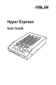
Hyper Express User Guide
E9496 First Edition October 2014 Copyright © 2014 ASUSTeK COMPUTER INC. All Rights Reserved. No part of this manual, including the products and software described in it, may be reproduced, transmitted, transcribed, stored in a retrieval system, or translated into any language in any form or by any means, except documentation kept by the purchaser for backup purposes, without the express written permission of ASUSTeK COMPUTER INC. (“ASUS”).
Contents 1. Package contents............................................................................ 4 2. Hyper Express specifications summary........................................ 5 3. Hyper Express hardware feature.................................................... 6 4. Recommended configurations....................................................... 7 5. 4.1 Qualified Vendors List for mSATA SSD.............................. 7 4.2 Qualified Vendors List for M.2 SATA SSD.................
1. Package contents Check your package for the following items: 1 x Hyper Express 1 x Support CD 1 x SATA Express cable 1 x 2-pin front panel led convert cable 1 x M.2 & mSATA screw package If any of the above items is damaged or missing, contact your retailer.
2. Hyper Express specifications summary Hyper Express allows you to install two M.2 or mSATA storage devices providing flexibility while enjoying the ultra-fast transfer speed of up to 10 Gb/s. Chipset ASMedia® 1062R RAID Controller Interface SATA Express interface (PCI Express 2.0 x2 bandwidth) External Connectors 1 x SATA Express connector 1 x 2-pin front panel led header(Q-LED header) 1 x mode switch button Lane 1 sockets*: 1 x M.
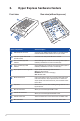
3. Hyper Express hardware feature Front view Rear view (without top cover) et2 k oc S et1 ck So Parts / components 6 e lan e lan Short description SATA Express connector Connects to the SATA Express header on the motherboard. Provides maximum data transfer rate of up to 10 Gb/s 2-pin front panel LED header (Q-LED header) Connects to the front panel LED of the chassis. Lane 2 sockets (S2) LED indicator Green LED lights up to indicate that a storage device (M.
4. Recommended configurations It is highly recommended that you install two M.2 card or two mSATA cards for the Normal mode (AHCI) or for the Super Speed mode (RAID 0) to ensure optimum performance and reliability. Always use the same size, type, and model of M.2 or mSATA SSD. Mixed configuration (one M.2 and one mSATA SSD) in Normal mode is possible but the performance and reliability is not guaranteed. For this kind of configuration, always install one M.2 SSD or one mSATA SSD on each lane.
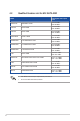
4.2 Qualified Vendors List for M.2 SATA SSD Super Speed mode speed ATTO Model 8 KINGSTON SM2280S3-120GB Read:752 MB/s Write:802 MB/s CRUCIAL M550-256GB Read:749 MB/s Write:799 MB/s CRUCIAL M550-128GB Read:749 MB/s Write:740 MB/s KINGSHARE KN300-128GB Read:749 MB/s Write:337 MB/s TRANSCEND TS512GMTS800-512GB Read:747 MB/s Write:610 MB/s TRANSCEND TS128GMTS600-128GB Read:749 MB/s Write:306 MB/s TRANSCEND TS64GMTS400-64GB Read:745 MB/s Write:159 MB/s TIGO M242-128GB Read:742.
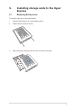
5. Installing storage cards to the Hyper Express 5.1 Removing the top cover To remove the top cover of the Hyper Express: 1. Place the Hyper Express on a flat and stable surface. 2. Remove the two screws at the rear. 3. Slide the top cover toward the rear then lift it it to remove. Set aside.
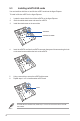
5.3 Installing mSATA SSD cards You can install two half-size or two full-size mSATA cards into the Hyper Express. To install a full-size mSATA to the Hyper Express: 1. Locate the screw hole for the full-size mSATA on the Hyper Express. 2. Get the bundled stand screw and screw for mSATA. 3. Install the stand screw on the screw hole. stand screw screw hole for mSATA 4.
5.4 Installing M.2 SATA SSD cards You can install two type 2242/2260/2280/22110 M.2 cards with Socket 3 M Key design into the Hyper Express. The M.2 connector supports SATA SSD only. To install a type 2260 M.2 card: 1. Locate the screw holes on the Hyper Express for the type of M.2 card to use. 2. Get the bundled stand screw and screw for your M.2 card. 3. Install the stand screw on the screw hole that corresponds to the type of M.2 card to use. stand screw screw slot for M.2 card 4.
To install type 2242/2260/22110 M.2 card, follow steps 1 to 6 in installing a type 2260 M.2 card. Install the stand screw on the screw slot corresponding to the type of M.2 card you to intend to use. 5.5 Replacing the top cover To replace the top cover of the Hyper Express card: 12 1. Align and place the top cover to the Hyper express. 2. Slide the top cover towards the front ensuring that the screw holes matches the screw holes on the rear of the Hyper Express. 3.
6. Installing Hyper Express to the chassis Before installing Hyper Express, ensure that you have an available 3.5-inch drive bay in your chassis. To install the Hyper Express to the chassis: 1. Align and insert the Hyper Express into an available 3.5-inch drive bay in your chassis. Match the screw holes of the Hyper Express to the screw holes on the chassis. 2. Secure the Hyper Express with two screws. 3. Prepare the bundled SATA Express cable and the Q-LED header cable.
4. Connect the SATA Express cable to the SATA Express connector on the motherboard. 5. Connect the Q-LED header cable to the connectors on the motherboard’s system panel connector. If a Q-connector is already installed, uninstall it first before installing the Q-LED header cable. 6. Connect chassis LED cable to Q-LED header cable as shown. Q-LED cable (with 2-pin led connector) SATA Express cable 7. Connect the other end of the SATA Express cable to the SATA Express connector on the Hyper Express.
9. Connect a SATA power cable from the power supply to the bundled SATA Express cable. SATA Express cable SATA power cable from power supply 7. Switching mode using the Mode change button To manually switch from Normal mode to Super Speed mode, press and hold the Mode switch button on the front panel of the Hyper Express for 5 seconds. To switch from Super Speed mode to Normal mode, press the Mode switch button twice. When the Super Speed mode change LED is OFF, Hyper Express is in Normal mode.
9. Using the Hyper Express Utility The user interface of the Hyper Express Utility is consists mainly of three main tabs. Hyper Express Mode, SSD information, and Benchmark. Always back up your data on the installed storage device before switching mode. The utility automatically initializes the installed storage device every time you switch modes. 9.
9.1.1 Switching from Normal mode to Super Speed mode To switch from Normal mode (default) to Super Speed mode: 1. From the Hyper Express Mode screen, click the Super Speed icon 2. From the Initialize Disk window of the Windows Disk Management application, put a check mark on Disk 0 from the Select disks pane, tick GPT (GUID Partition Table) from the Use the following partition style for the selected disks:, then click OK to initialize the disk. 3. When done, click OK. 4. .
9.1.2 Switching from Super Speed mode to Normal mode To switch from the Super Speed mode to the Normal mode: 1. From the Hyper Express Mode screen, click the Normal icon . 2. From the Initialize Disk window of the Windows Disk Management application, put a check mark on Disk 0 from the Select disks pane, tick GPT (GUID Partition Table) from the Use the following partition style for the selected disks:, then click OK to initialize the disk. 3. When done, click OK. 4.
9.2 SSD information Displays information about the storage device installed on your Hyper Express.
9.3 Benchmark The Benchmark feature displays the read and write speed of the installed storage device when activated.
Notices Federal Communications Commission Statement This device complies with Part 15 of the FCC Rules. Operation is subject to the following two conditions: • This device may not cause harmful interference. • This device must accept any interference received including interference that may cause undesired operation. This equipment has been tested and found to comply with the limits for a Class B digital device, pursuant to Part 15 of the FCC Rules.
Canadian Department of Communications Statement This digital apparatus does not exceed the Class B limits for radio noise emissions from digital apparatus set out in the Radio Interference Regulations of the Canadian Department of Communications. This class B digital apparatus complies with Canadian ICES-003. VCCI: Japan Compliance Statement Class B ITE This is a Class B product based on the standard of the VCCI Council.
ASUS contact information ASUSTeK COMPUTER INC. Address 15 Li-Te Road, Peitou, Taipei, Taiwan 11259 Telephone +886-2-2894-3447 Fax +886-2-2890-7798 E-mail info@asus.com.tw Web site http://www.asus.com Technical Support Telephone Fax Online support +86-21-3842-9911 +86-21-5866-8722, ext. 9101# http://support.asus.com/techserv/techserv.
(510)739-3777/(510)608-4555 800 Corporate Way, Fremont, CA 94539. Asus Computer International Date : Signature : Representative Person’s Name : Jul. 24, 2014 Steve Chang / President This device complies with part 15 of the FCC Rules. Operation is subject to the following two conditions: (1) This device may not cause harmful interference, and (2) this device must accept any interference received, including interference that may cause undesired operation.