® TUSL2 Intel® 815E ATX Motherboard USER’S MANUAL
USER'S NOTICE No part of this manual, including the products and software described in it, may be reproduced, transmitted, transcribed, stored in a retrieval system, or translated into any language in any form or by any means, except documentation kept by the purchaser for backup purposes, without the express written permission of ASUSTeK COMPUTER INC. (“ASUS”).
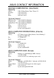
ASUS CONTACT INFORMATION ASUSTeK COMPUTER INC. (Asia-Pacific) Marketing Address: Telephone: Fax: Email: 150 Li-Te Road, Peitou, Taipei, Taiwan 112 +886-2-2894-3447 +886-2-2894-3449 info@asus.com.tw Technical Support MB/Others (Tel): +886-2-2890-7121 (English) Notebook (Tel): +886-2-2890-7122 (English) Desktop/Server (Tel):+886-2-2890-7123 (English) Fax: +886-2-2895-9254 Email: tsd@asus.com.tw WWW: www.asus.com.tw FTP: ftp.asus.com.
CONTENTS 1. INTRODUCTION ............................................................................. 7 1.1 How This Manual Is Organized .................................................. 7 1.2 Item Checklist ............................................................................. 7 2. FEATURES ........................................................................................ 8 2.1 The ASUS TUSL2 ...................................................................... 8 2.
CONTENTS 4.5 Power Menu .............................................................................. 71 4.5.1 Power Up Control .......................................................... 73 4.5.2 Hardware Monitor ......................................................... 75 4.6 Boot Menu ................................................................................ 76 4.7 Exit Menu ................................................................................. 78 5. SOFTWARE SETUP ......................
FCC & DOC COMPLIANCE Federal Communications Commission Statement This device complies with FCC Rules Part 15. Operation is subject to the following two conditions: • • This device may not cause harmful interference, and This device must accept any interference received, including interference that may cause undesired operation. This equipment has been tested and found to comply with the limits for a Class B digital device, pursuant to Part 15 of the FCC Rules.
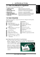
1. INTRODUCTION 1. INTRODUCTION Manual / Checklist 1.1 How This Manual Is Organized This manual is divided into the following sections: 1. 2. 3. 4. 5. 6. 7. INTRODUCTION FEATURES HARDWARE SETUP BIOS SETUP SOFTWARE SETUP SOFTWARE REFERENCE APPENDIX Manual information and checklist Production information and specifications Intructions on setting up the motherboard.
2. FEATURES 2.1 The ASUS TUSL2 The ASUS TUSL2 motherboard is carefully designed for the demanding PC user who wants advanced features processed by the fastest processors. 2.1.1 Specifications • 2.
2. FEATURES • • • • • • • • • • • • ASUS JumperFree™ Mode: JumperFree Mode supplies precise overclocking of CPU external (FSB) frequency in 1 MHz increments through the BIOS. JumperFree also permits Vcore voltage adjustments through BIOS setup. Alternatively, easy-to-use DIP switches instead of jumpers are supplied onboard for manual adjustment of the processor’s external frequency.
2. FEATURES 2.1.2 Specifications–Optional Components 2. FEATURES Performance The following onboard components are optional at the time of purchase: • Onboard Audio: C-Media Audio Chip CMI8738 supporting the latest PCI 6 channel and HRTF 3D Audio sound circuitry. A software package helps setup the multi-channel PC sound system. • Promise ® chip: Available on the TUSL2, the Promise IDE controller chip supports the ATA-100 protocol and Ultra DMA/100 data transfer speeds.
2. FEATURES 2.1.4 Intelligence • • • • • • • Fan Status Monitoring and Alarm: To prevent system overheat and system damage, the CPU, power supply, and system fans can be monitored for RPM and failure. All the fans are set for its normal RPM range and alarm thresholds. Temperature Monitoring and Alert: To prevent system overheat and system damage, this motherboard supports processor thermal sensing and auto-protection.
2. FEATURES 2.2 TUSL2 Motherboard Components See opposite page for locations. Location Processor Support Socket 370 Pentium III/Celeron/Tualatin (FC-PGA/2) CPUs . 2 Feature Setting DIP Switches ................................................... 6 2. FEATURES MB Components Chipsets Intel 815E Graphics Memory Controller Hub (GMCH) .......... 3 Intel I/O Controller Hub 2 (ICH2) ......................................... 14 Promise IDE ATA100 / RAID 1/0 Controller (optional) ..........
2. FEATURES 2.2.1 Component Locations 1 2 3 4 5 6 7 8 2.
3. HARDWARE SETUP 3.
3. HARDWARE SETUP 3.2 Layout Contents Motherboard Settings 1) JEN 2) JP3 3) JP4 4) USBPWR01 USBPWR23 5) OC3 6) KBPWR 7) DSW 8) VIO 9) BCS p.18 p.19 p.19 p.20 JumperFree™ Mode (Enable/Disable) ATA100 / RAID 0/1 (Enable) Onboard IDE (Enable/Disable) USB Device Wake Up (Enable/Disable) p.21 p.21 p.22 p.24 p.24 USB/CNR Selection (Enable USB23 / Enable CNR) Keyboard Power Up (Enable / Disable) CPU External Frequency Setting Voltage I/O Setting (3.3V/3.40V/3.60V) Bass Center Setting (Type 1 / Type 2) p.25 p.
3. HARDWARE SETUP 18) 19) 20) 21) 3. H/W SETUP Layout Contents 16 ACHA WOL_CON WOR_CON LCDTV p.40 p.41 p.41 p.42 Chassis Intrusion Connector (2 pins) Wake-On-LAN Connector (3 pins) Wake-On-Ring Connector (2 pins) LCD-TV Headers (18-1 pins/18 pins) 22) USB23 23) SMARTCON 24) ATXPWR p.42 USB Headers (5-1 pins, Two 10-1 pins) p.42 ASUS SmartCard Connector (10-1 pin) p.43 ATX Power Supply Connector (20 pins) 25) JTPWR p.43 Power Supply Thermal Sensor Connector (2 pins) 26) PWRLED (PANEL) p.
3. HARDWARE SETUP 3.3 Hardware Setup Procedure Before using your computer, you must complete the following steps: • Check Motherboard Settings • Install Memory Modules • Install the Central Processing Unit (CPU) • Install Expansion Cards • Connect Ribbon Cables, Panel Wires, and Power Supply 3.4 Motherboard Settings 3. H/W SETUP Motherboard Settings WARNING! Computer motherboards and expansion cards contain very delicate Integrated Circuit (IC) chips.
3. HARDWARE SETUP Motherboard Feature Settings The motherboard’s onboard functions are either adjusted through jumpers or DIP switches. When using DIP switches, the white block represents the switch’s position. The example below shows all the switches in the OFF position. ON 1 2 3 4 5 DSW ON OFF COM1 ® TUSL2 TUSL2 DIP Switches 1. Frequency Selection 2. Frequency Selection 3. Frequency Selection 4. Frequency Selection 5. Frequency Selection. 3.
3. HARDWARE SETUP 2) ATA100 / RAID 0/1 (JP3) These jumpers enable either the ATA100 IDE Controller, or the IDE RAID controller function. The default setting is ATA100. Setting JP3 Enable ATA100 [2-3] (default) Enable RAID 0/1 [1-2] COM1 JP3 1 2 2 3 ® RAID0/1 TUSL2 ATA100 3. H/W SETUP Motherboard Settings (Default) TUSL2 ATA100/RAIDO Selection 3) Onboard IDE ( JP4) These jumpers enable or disable the IDE function of the motherboard.
3. HARDWARE SETUP 4) USB Device Wake Up (USBPWR01, USBPWR23) These allow you to disable or enable the USB device wake up function. Set these jumpers to Enable if you wish to use your USB devices to wake up your computer. This feature requires an ATX power supply that can supply at least 2A on the +5VSB lead. The default is set to Disable because not all computers have the appropriate ATX power supply. Your computer will not power ON if you set this to Enable and do not have the appropriate ATX power supply.
3. HARDWARE SETUP 5) USB/CNR Selection (OC3) This jumper switches the circuit power between the USB23 connector and the CNR slot. Note that the default is set to power the USB23 connector. Setting Enable CNR Enable USB23 OC3 [1-2] [2-3] (default) COM1 OC3 1 2 2 3 ® USB on CNR TUSL2 USB23 (Default) TUSL2 USB/CNR Selection 6) Keyboard Power Up (KBPWR) This allows you to disable or enable the keyboard power up function.
3. HARDWARE SETUP 7) CPU External Frequency Setting (DSW) This option tells the clock generator what frequency to send to the CPU, DRAM, AGP, and the PCI bus. This allows the selection of the CPU’s External frequency. IMPORTANT: 1. In JumperFree mode, all dip switches must be set to OFF. 2. When JumperFree mode is enabled, use BIOS setup in place of these switches (see CPU Speed in Advanced Menu in BIOS Setup). NOTE: Only selected switches are illustrated. For a complete frequency listing, see next page.
3. HARDWARE SETUP External Frequency Table The following table is for use by experienced motherboard installers only. Overclocking can result in system instability or even shortening the life of the processor. 66:100 66:100 66:100 66:100 66:100 66:100 66:100 66:100 100:100 100:100 100:100 100:100 100:100 100:100 100:100 100:100 133:133 133:133 133:133 133:133 133:133 133:133 133:133 133:133 133:100 133:100 133:100 133:100 133:100 133:100 133:100 133:100 64.4 60.0 66.0 68.3 70.0 75.0 80.0 83.0 99.6 90.
3. HARDWARE SETUP 8) Voltage I/O Setting (VIO) This jumper allows you to select the voltage supplied to the DRAM, chipset, AGP, and PCI. The default setting of 3.40V should be used unless processor overclocking requires a higher voltage. Setting VIO 3.30 V [1-2] 3.40 V [2-3] (default) 3.60 V [3-4] VIO COM1 2 1 3.30 V ® 4 3 3 2 3.40 V 3.60 V 3.
3. HARDWARE SETUP 3.5 System Memory (DIMM) NOTE: No hardware or BIOS setup is required after adding or removing memory. This motherboard uses only Dual Inline Memory Modules (DIMMs). Sockets are available for 3.3Volt (power level) unbuffered Synchronous Dynamic Random Access Memory (SDRAM). One side (with memory chips) of the DIMM takes up one row on the motherboard. Memory speed setup is recommended through SDRAM Configuration in 4.4.1 Chip Configuration.
3. HARDWARE SETUP 3.5.2 Memory Installation WARNING! Make sure that you unplug your power supply when adding or removing memory modules or other system components. Failure to do so may cause severe damage to both your motherboard and expansion cards (see 3.3 Hardware Setup Procedure for more information). Insert the module(s) as shown. Because the number of pins are different on either side of the breaks, the module will only fit in the orientation shown.
3. HARDWARE SETUP 3.6 Central Processing Unit (CPU) The motherboard provides a ZIF Socket 370, for CPU installation. A fan and heatsink should be attached to the CPU to prevent overheating. Purchase and install a fan and heatsink before turning on the system. COM1 Coppermine/ Celeron Gold Arrow ® Tualatin TUSL2 TUSL2 Socket 370 Gold Arrow ASUS TUSL2 User’s Manual 3. H/W SETUP System Memory 1. Locate the Socket 370 and open it by pulling the lever gently sideways away from the socket.
3. HARDWARE SETUP 3.7 Expansion Cards In the future, you may need to install expansion cards. The motherboard has five PCI expansion slots to support these cards. Follow the steps in the next section when installing expansion cards. WARNING! Unplug the system power cord when adding or removing expansion cards or other system components. Failure to do so may cause severe damage to both the motherboard and expansion cards. 3.7.1 Installing an Expansion Card 3. H/W SETUP CPU 1.
3. HARDWARE SETUP 3.7.2 Assigning IRQs for Expansion Cards Some expansion cards need an IRQ to operate. Generally, an IRQ must be exclusively assigned to one use. In a standard design, there are 16 IRQs available but most of them are already in use, leaving 6 IRQs free for expansion cards. If your motherboard has PCI audio onboard, an additional IRQ will be used. If your motherboard also has MIDI enabled, another IRQ will be used, leaving 4 IRQs free.
3. HARDWARE SETUP 3.7.3 Communication and Networking Riser (CNR) Slot This connector supports specially designed network, audio, or modem riser cards. Main processing is done through software and controlled by the motherboard’s system chipset. This provides upgradeable network, audio, and/or modem solutions at an incredibly low cost. NOTE: A CNR is not included with this motherboard. COM1 ® TUSL2 3.
3. HARDWARE SETUP 3.7.4 Accelerated Graphics Port (AGP) Pro Slot This motherboard provides an accelerated graphics port (AGP) pro slot to support a new generation of AGP graphics cards with ultra-high memory bandwidth. COM1 AGP Card without Retention Notch ® TOP VIEW TUSL2 20-pin bay Rib (inside slot) 28-pin bay Rib 3. H/W SETUP Expansion Cards TUSL2 Accelerated Graphics Port (AGP PRO) CAUTION! The AGP Pro slot is shipped with a warning label over the 20-pin bay.
3. HARDWARE SETUP 3.8 External Connectors WARNING! Some pins are used for connectors or power sources. These are clearly distinguished from jumpers in the Motherboard Layout. Placing jumper caps over these connector pins will cause damage to your motherboard. IMPORTANT: Ribbon cables should always be connected with the red stripe to Pin 1 on the connectors. Pin 1 is usually on the side closest to the power connector on hard drives and CD-ROM drives, but may be on the opposite side on floppy disk drives.
3. HARDWARE SETUP 3) Universal Serial BUS Ports 0 & 1 (Black two 4-pin USB) Two USB ports are available for connecting USB devices. For additional USB ports, you can use the USB headers (see USB Headers later in this section) and mount it to the chassis. USB 1 Universal Serial Bus (USB) 2 3. H/W SETUP Connectors 4) Parallel Port Connector (Burgundy 25-pin PRINTER) You can enable the parallel port and choose the IRQ through Onboard Parallel Port (see 4.4.2 I/O Device Configuration).
3. HARDWARE SETUP 6) Serial Port Connectors (Teal/Turquoise 9-pin COM1, 10-1 pin COM2) One serial port is ready for a mouse or other serial devices. A second serial port is available using a serial port bracket connected from the motherboard to an expansion slot opening. See Onboard Serial Port 1/2 in 4.4.2 I/O Device Configuration for settings. COM 1 Serial Port (9-pin male) 3.
3. HARDWARE SETUP 8) Audio Port Connectors (Three 1/8” Line_In, Line_Out, Mic) (optional) Line Out (lime) can be connected to headphones or preferably powered speakers. Line In (light blue) allows tape players or other audio sources to be recorded by your computer or played through the Line Out (lime). Mic (pink) allows microphones to be connected for inputting voice. See Section 6.
3. HARDWARE SETUP ® 2 Primary ATAIDE Con. 12 Primary IDE Con. COM1 Secondary IDE Con. 1 Secondary ATAIDE Con. 3. H/W SETUP Connectors 10) Primary (Blue) / Secondary (Black) IDE Connectors (40-1 pin PRIMARY IDE and SECONDARY IDE) (40-1 pin PRIMARY ATAIDE and SECONDARY ATAIDE) These connectors support the IDE hard disk ribbon cables supplied with the motherboard. Connect the cable’s blue connector to the motherboard’s primary IDE connector (recommended) or the secondary IDE connector.
3. HARDWARE SETUP 11) IDE Activity LED (2-pin IDELED) This connector supplies power to the cabinet’s IDE activity LED. Read and write activity by devices connected to the Primary or Secondary IDE connectors will cause the LED to light up. COM1 TIP: If the case-mounted LED does not light, try reversing the 2-pin plug. IDELED ® TUSL2 TUSL2 IDE Activity LED 3.
3. HARDWARE SETUP 13) Internal Audio Connectors (4-pin CD1, AUX, MODEM) These connectors allow you to receive stereo audio input from such sound sources as a CD-ROM, TV tuner, or MPEG card. The MODEM connector allows the onboard audio to interface with a voice modem card with a similar connector. ® MODEM Ground CD (Black) Left Audio Channel AUX (White) Right Audio Channel COM1 Modem-In Ground Modem-Out TUSL2 TUSL2 Internal Audio Connectors 3.
3. HARDWARE SETUP 15) Internal Microphone Connector (3-pin MIC2) This connector allows you to connect chassis mounted microphone to the motherboard instead of having to attach an external microphone onto the ATX connectors. COM1 MIC2 3 Ground MIC Input MIC Power 1 ® TUSL2 3.
3. HARDWARE SETUP 17) ASUS iPanel Audio Connector (12-1 pin AAPANEL) Connect the audio cable from the optional ASUS iPanel to this for front panel audio control. COM1 AAPANEL MIC2 AGND Line in_L AGND2 Line in_R ® MICPWR Line out_L AGND3 Line out_R TUSL2 TUSL2 Audio Panel Connectors 3. H/W SETUP Connectors 18) Chassis Intrusion Lead (2-pin ACHA) This lead is for a chassis designed for chassis intrusion detection.
3. HARDWARE SETUP 19) Wake-On-LAN Connector (3-pin WOL_CON) This connector connects to a LAN card with a Wake-On-LAN output, such as the ASUS PCI-L101 Ethernet card (see 7. Appendix). The connector powers up the system when a wakeup packet or signal is received through the LAN card. IMPORTANT: This feature requires that Wake On LAN or PCI Modem is enabled (see 4.5.1 Power Up Control) and that your system has an ATX power supply with at least 720mA +5V standby power.
3. HARDWARE SETUP 21) LCD-TV Headers (18-pin, 18-1 pin LCD TV) These headers require optional modules for LCD or TV output. LCDTV COM1 1 +5V PCIRST# DD10 GND DD8 DD6 CLKOUT0 GND ® +5V GND DD11 DD9 DD7 GND DD5 CLKOUT1 +1.8V LTVDA GND BLANK TVHSYNC GND DD2 DD0 LTVCL +3V ROMSEN TVVSYNC GND DD4 DD3 DD1 GND TUSL2 TUSL2 LCD-TV Headers 3. H/W SETUP Connectors 22) USB Header (10-1 pin USB23) If the USB Ports on the back panels are inadequate,one USB header is available for two additional USB ports.
3. HARDWARE SETUP 24) ATX Power Supply Connector (20-pin block ATXPWR) This connector connects to an ATX power supply. The plug from the power supply will only insert in one orientation because of the different hole sizes. Find the proper orientation and push down firmly making sure that the pins are aligned.
3. HARDWARE SETUP The following is for items 26–32 ® Message LED TUSL2 SMI Lead Reset Ground MLED+ MLEDExtSMI# Ground PWR GND PLED+ PLEDKeylock Ground Power LED COM1 Speaker Connector +5V Ground Ground Speaker Keyboard Lock Reset SW ATX Power Switch* * Requires an ATX power supply. TUSL2 System Panel Connectors 3.
3. HARDWARE SETUP 3.9 Starting Up the First Time 1. After all connections are made, close the system case cover. 2. Be sure that all switches are off (in some systems, marked with ), and the power input voltage is set to comply with the standard used in your country (220V-240V or 110-120V). 3. Connect the power supply cord into the power supply located on the back of your system case according to your system user’s manual. 4.
3. HARDWARE SETUP 7. During power-on, hold down to enter BIOS setup. Follow the instructions in 4. BIOS SETUP. * Powering Off your computer: You must first exit or shut down your operating system before switching off the power switch. For ATX power supplies, you can press the ATX power switch after exiting or shutting down your operating system.
4. BIOS SETUP 4.1 Managing and Updating Your BIOS 4.1.1 Upon First Use of the Computer System It is recommended that you save a copy of the original motherboard BIOS along with a Flash Memory Writer utility (AFLASH.EXE) to a bootable floppy disk in case you need to reinstall the BIOS later. AFLASH.EXE is a Flash Memory Writer utility that updates the BIOS by uploading a new BIOS file to the programmable flash ROM on the motherboard. This file works only in DOS mode.
4. BIOS SETUP 5. Select 1. Save Current BIOS to File from the Main menu and press . The Save Current BIOS To File screen appears. 6. Type a filename and the path, for example, A:\XXX-XX.XXX and then press . 4.1.2 Updating BIOS Procedures WARNING! Only update your BIOS if you have problems with your motherboard and you know that the new BIOS revision will solve your problems. Careless updating can result in your motherboard having more problems! 4. BIOS SETUP Updating BIOS 1.
4. BIOS SETUP 6. When prompted to confirm the BIOS update, press Y to start the update. 4. BIOS SETUP Updating BIOS 7. The utility starts to program the new BIOS information into the flash ROM. The boot block will be updated automatically only when necessary. This will minimize the chance that a failed update will prevent your system from booting up. When the programming is finished, Flashed Successfully will be displayed.
4. BIOS SETUP 8. Follow the onscreen instructions to continue. WARNING! If you encounter problems while updating the new BIOS, DO NOT turn off your system since this might prevent your system from booting up. Just repeat the process, and if the problem still persists, update the original BIOS file you saved to disk above. If the Flash Memory Writer utility was not able to successfully update a complete BIOS file, your system may not be able to boot up. If this happens, your system will need servicing. 4.
4. BIOS SETUP 4.2 BIOS Setup Program This motherboard supports a programmable EEPROM that can be updated using the provided utility as described in 4.1 Managing and Updating Your BIOS. The utility is used if you are installing a motherboard, reconfiguring your system, or prompted to “Run Setup”. This section describes how to configure your system using this utility. Even if you are not prompted to use the Setup program, at some time in the future you may want to change the configuration of your computer.
4. BIOS SETUP 4.2.1 BIOS Menu Bar The top of the screen has a menu bar with the following selections: MAIN Use this menu to make changes to the basic system configuration. ADVANCED Use this menu to enable and make changes to the advanced features. POWER Use this menu to configure and enable Power Management features. BOOT Use this menu to configure the default system device used to locate and load the Operating System. EXIT Use this menu to exit the current menu or specify how to exit the Setup program.
4. BIOS SETUP General Help In addition to the Item Specific Help window, the BIOS setup program also provides a General Help screen. This screen can be called up from any menu by simply pressing or the + combination. The General Help screen lists the legend keys with their corresponding alternates and functions. Saving Changes and Exiting the Setup Program See 4.7 Exit Menu for detailed information on saving changes and exiting the setup program.
4. BIOS SETUP 4.3 Main Menu When the Setup program is accessed, the following screen appears: 4. BIOS SETUP Main Menu System Time [XX:XX:XX] Sets your system to the time that you specify (usually the current time). The format is hour, minute, second. Valid values for hour, minute and second are Hour: (00 to 23), Minute: (00 to 59), Second: (00 to 59). Use the or + keys to move between the hour, minute, and second fields.
4. BIOS SETUP 4.3.1 Primary & Secondary Master/Slave 4. BIOS SETUP Master/Slave Drives NOTE: Before attempting to configure a hard disk drive, make sure you have the configuration information supplied by the manufacturer of the drive. Incorrect settings may cause your system to not recognize the installed hard disk. To allow the BIOS to detect the drive type automatically, select [Auto]. Type [Auto] Select [Auto] to automatically detect an IDE hard disk drive.
4. BIOS SETUP IMPORTANT: If your hard disk was already formatted on an older previous system, incorrect parameters may be detected. You will need to enter the correct parameters manually or use low-level format if you do not need the data stored on the hard disk. If the parameters listed differ from the ones used when the disk was formatted, the disk will not be readable.
4. BIOS SETUP Head This field configures the number of read/write heads. Refer to your drive documentation to determine the correct value to enter into this field. NOTE: To make changes to this field, the Type field must be set to [User Type HDD] and the Translation Method field must be set to [Manual]. Sector This field configures the number of sectors per track. Refer to your drive documentation to determine the correct value to enter into this field.
4. BIOS SETUP Other options for “Type:” are: [CD-ROM] - for IDE CD-ROM drives [LS-120] - for LS-120 compatible floppy disk drives [ZIP-100] - for ZIP-100 compatible disk drives [MO] - for IDE magneto optical disk drives [Other ATAPI Device] - for IDE devices not listed here After using the legend keys to make your selections on this sub-menu, press the key to exit back to the Main menu.
4. BIOS SETUP Language [English] This allows selection of the BIOS’ displayed language. Currently only English is available. Supervisor Password [Disabled] / User Password [Disabled] These fields allow you to set the passwords. To set the password, highlight the appropriate field and press . Type in a password and press . You can type up to eight alphanumeric characters. Symbols and other keys are ignored. To confirm the password, type the password again and press the .
4. BIOS SETUP 4.4 Advanced Menu CPU Internal Frequency In JumperFree™ Mode, this field allows you to select the internal frequency of your CPU. Select [Manual] if you want to make changes to the subsequent 2 fields. Note that selecting a frequency higher than the CPU manufacturer recommends may cause the system to hang or crash. See System Hangup on page 60. 4.
4. BIOS SETUP CPU Vcore In JumperFree mode, this field displays the core voltage supplied to the CPU. If you want to set it manually, always refer to the CPU documentation. The picture shown here provides only an example of possible Vcore ranges. CPU Level 1 Cache, CPU Level 2 Cache [Enabled] These fields allow you to choose from the default of [Enabled] or choose [Disabled] to turn on or off the CPU’s Level 1 and Level 2 built-in cache.
4. BIOS SETUP Notes for JumperFree Mode CPU Upgrade/Reinstallation To ensure that your system can enter BIOS setup after the processor has been changed or reinstalled, your system will start up running at a bus speed of 66MHz and a fail-safe CPU internal frequency (4x66MHz). It will then automatically take you to the Advanced menu with a popup menu of all the officially possible CPU internal frequencies. 4.
4. BIOS SETUP 4.4.1 Chip Configuration (Scroll down to see more items as shown.) 4. BIOS SETUP Chip Configuration SDRAM Capability This field displays the capability of the memory modules that you are using—either PC100 or PC133. SDRAM Operating Mode This field displays the current SDRAM operating mode (PC100 or PC133) according to the SDRAM frequency you configure in the Advanced menu. SDRAM Timing [By SPD] This sets the optimal timings for items 4-7, depending on the memory modules that you are using.
4. BIOS SETUP SDRAM RAS to CAS Delay This controls the latency between the SDRAM active command and the read/write command. SDRAM RAS Precharge Time This controls the idle clocks after issuing a precharge command to the SDRAM. SDRAM Cycle Time (Tras, Trc) [6T, 8T] This feature controls the number of SDRAM clocks used for SDRAM parameters Tras and Trc. Tras specifies the minimum clocks required between active command and precharge command.
4. BIOS SETUP Memory Hole At 15M-16M [Disabled] This field allows you to reserve an address space for ISA devices that require it. Configuration options: [Disabled] [Enabled] PCI 2.1 Support [Enabled] This function allows you to enable or disable PCI 2.1 features including passive release and delayed transaction. Configuration options: [Disabled] [Enabled] High Priority PCI Mode [Disabled] This field allows you to give PCI slot 1 a higher priority.
4. BIOS SETUP 4.4.2 I/O Device Configuration (Scroll down to see more items as shown.) 4. BIOS SETUP I/O Device Config Onboard AC97 Modem Controller [Auto] Onboard AC97 Audio Controller [Auto] [Auto] allows the motherboard’s BIOS to detect whether you are using any modem/audio device. If a modem/audio device is detected, the onboard modem/audio controller will be enabled; if no modem/audio device is detected, the onboard modem/audio controller will be disabled.
4. BIOS SETUP UART2 Use [COM Port] When IR is enabled, this field activates the onboard standard infrared feature and sets the second serial UART to support the infrared module connector on the motherboard. If your system already has a second serial port connected to the onboard COM2 connector, it will no longer work if you enable the infrared feature. To support a Smart Card Reader, select Card Reader.
4. BIOS SETUP 4.4.3 PCI Configuration Slot 1/5, Slot 2, Slot 3, Slot 4, Slot 6 IRQ [Auto] These fields set how IRQ use is determined for each PCI slot. The default setting for each field is [Auto], which utilizes auto-routing to determine IRQ use. Configuration options: [Auto] [NA] [3] [4] [5] [7] [9] [10] [11] [12] [14] [15] 4. BIOS SETUP PCI Configuration PCI/VGA Palette Snoop [Disabled] Some nonstandard VGA cards, such as graphics accelerators or MPEG video cards, may not show colors properly.
4. BIOS SETUP USB Function [Enabled] This motherboard supports Universal Serial Bus (USB) devices. Set to [Enabled] if you want to use USB devices. Configuration options: [Disabled] [Enabled] Primary VGA BIOS Sequence [PCI Card] If the computer has both PCI and AGP VGA controllers, this field allows you to select which of the controllers will act as your primary graphics controller. The default, [PCI Card], gives precedence to the PCI controller when detected.
4. BIOS SETUP 4.4.4 Shadow Configuration Video ROM BIOS Shadow [Enabled] This field allows you to change the video BIOS location from ROM to RAM. Relocating to RAM enhances system performance, as information access is faster than the ROM. Configuration options: [Disabled] [Enabled] 4. BIOS SETUP Shadow Configuration C8000-DFFFF Shadow [Disabled] These fields are used for shadowing other expansion card ROMs.
4. BIOS SETUP 4.5 Power Menu The Power menu allows you to reduce power consumption. This feature turns off the video display and shuts down the hard disk after a period of inactivity. 4. BIOS SETUP Power Menu Power Management [User Define] This option must be enabled to use any of the automatic power saving features. If this menu item is set to [Disabled], power management features will not function regardless of other field settings on this menu.
4. BIOS SETUP Video Off Option [Suspend -> Off ] This field determines when to activate the video off feature for monitor power management. Configuration options: [Always On] [Suspend -> Off] Video Off Method [DPMS OFF] This field defines the video off features. The DPMS (Display Power Management System) feature allows the BIOS to control the video display card if it supports the DPMS feature. [Blank Screen] only blanks the screen (use this for monitors without power management or “green” features.
4. BIOS SETUP 4.5.1 Power Up Control 4. BIOS SETUP Power Up Control AC PWR Loss Restart [Disabled] This allows you to set whether you want your system to reboot after the power has been interrupted. [Disabled] leaves your system off and [Enabled] reboots your system. [Previous State] sets your system back to the state it is before the power interruption.
4. BIOS SETUP Wake On PS2 KB/PS2 Mouse/CIR [Disabled] Set this field to [Enabled] if you wish to use your PS2 keyboard, PS2 mouse, or consumer IR device to power up your computer. This feature requires an ATX power supply that can supply at least 300mA on the +5VSB lead. The default is set to [Disabled] because not all computers have the appropriate ATX power supply. Your computer will not power ON if you set this to [Enabled] and do not have the appropriate ATX power supply.
4. BIOS SETUP 4.5.2 Hardware Monitor MB Temperature [xxxC/xxxF] CPU Temperature [xxxC/xxxF] The onboard hardware monitor is able to detect the MB (motherboard) and CPU temperatures. Set to [Ignore] only if necessary. 4. BIOS SETUP Hardware Monitor JTPWR Temperature [Ignore] [xxxC/xxxF] For additional onboard hardware monitoring, the JTPWR temperature is displayed if the lead is properly connected.
4. BIOS SETUP 4.6 Boot Menu Boot Sequence 4. BIOS SETUP Boot Menu The Boot menu allows you to select among the four possible types of boot devices listed using the up and down arrow keys. By using the <+> or key, you can promote devices and by using the <-> key, you can demote devices. Promotion or demotion of devices alters the priority which the system uses to search for a boot device on system power up.
4. BIOS SETUP SCSI/Promise Boot Sequence [Promise/SCSI] This selection determines the priority for booting from SCSI or the onboard Promise IDE controller. Configuration options: [Promise/SCSI] [SCSI/Promise] Plug & Play O/S [No] This field allows you to use a Plug-and-Play (PnP) operating system to configure the PCI bus slots instead of using the BIOS. When [Yes] is selected, interrupts may be reassigned by the OS.
4. BIOS SETUP 4.7 Exit Menu Once you have made all of your selections from the various menus in the Setup program, you should save your changes and exit Setup. Select Exit from the menu bar to display the following menu: 4. BIOS SETUP Exit Menu NOTE: Pressing does not exit this menu. You must select one of the options from this menu or from the legend bar to exit this menu.
4. BIOS SETUP Load Setup Defaults This option allows you to load the default values for each of the parameters on the Setup menus. When this option is selected or if is pressed, a confirmation is requested. Select [Yes] to load default values. You can now select Exit Saving Changes or make other changes before saving the values to the non-volatile RAM. Discard Changes This option allows you to discard the selections you made and restore the values you previously saved.
4. BIOS SETUP (This page was intentionally left blank.) 4.
5. SOFTWARE SETUP 5.1 Install Operating System You should always use the latest operating system and updates when using new hardware to ensure full compliancy. You may use any version of Windows 98/2000/ Millenium, but for Windows 95, you must use OSR 2.0 or later. For Windows NT 4.0, you must use Service Pack 3.0 or later. NOTE: To configure your system to use the RAID 0 or 1 option, you must run the FastTrack100™ BIOS before installing the OS.
5. SOFTWARE SETUP 5.3 TUSL2 Motherboard Support CD NOTE: The support CD contents are subject to change at any time without notice. To begin using your support CD disc, just insert it into your CD-ROM drive and the support CD installation menu should appear. If the menu does not appear, doubleclick or run E:\ASSETUP.EXE (assuming that your CD-ROM drive is drive E:). 5.3.1 Installation Menu • 5.
5. SOFTWARE SETUP • • • • • • • • Windbond Smart Manager Application: Installs the Smart Manager program, base components and drivers to read smart cards for system security and file encryption. PC-Cillin 2000Vx.xx: Installs the PC-Cillin virus protection software. View the online help for more information. Adobe Acrobat Reader Vx.x: Installs the Adobe Acrobat Reader software necessary to view user’s manuals saved in PDF format.
5. SOFTWARE SETUP 5.4 Using the Promise Chip for RAID 0 or 1 The Promise® chip, PDC20265R, onboard the TUSL2, offers a high performance Redundant Array of Independent Disks (RAID) configuration that supports only UltraATA-100/66/33, EIDE or FastATA-2 hard disks. After connecting two hard disks to the motherboard, activating either RAID 0 or 1 function is easily configured through the FastTrak100™ “Lite” firmware BIOS during boot up.
5. SOFTWARE SETUP 5.4.1 Installing the Hard Disks The RAID 0 setting allows users to reformat two hard disks with the same new OS simultaneously. RAID 1 arrays can use a pre-existing hard disk along with a blank hard disk, or two new hard disks. 1. Install the first and second hard disk into the hard disk bays of your system. Connect each hard disk drive with a separate UltraDMA/100 cable, one to the Primary ATA IDE1 connector, and the other to the Secondary ATA IDE2 connector onboard the TUSL2. 2.
5. SOFTWARE SETUP 5.4.3 Creating a RAID 0 Array 1. In the FastBuild™ Utility Main Menu, select Auto Setup [1]. The screen below is displayed. The Auto Setup Options Menu configures hard disks for RAID 0 and RAID 1 arrays. These selections assign all available drives that are appropriate for the new array and configures data formats and the IDE channels. FastBuild (tm) Utility 1.31 (c) 1996-2000 Promise Technology, Inc.
5. SOFTWARE SETUP 5.4.4 Creating a RAID 1 Array 1. In the FastBuild™ Utility Main Menu, select Auto Setup [1]. FastBuild (tm) Utility 1.31 (c) 1996-2000 Promise Technology, Inc. Optimize Array for: [ Auto Setup Options Menu ] Security Typical Application to use: Not Available [ Array Setup Configuration ] Mode ........................................ Mirror Spare Drive.................................. 0 Drive(s) Used in Array....................... 2 Array Disk Capacity (size in MB).............
5. SOFTWARE SETUP 5. The utility prompts: Please Select A Source Disk. Choose the pre-existing hard disk as the source and then a new, blank hard disk as the target. Then select to save the selection. The utility prompts a choice between to continue and to stop and escape. Choosing begins to duplicate the source hard disk onto the target hard disk. 6. To configure two new blank hard disks in a RAID 1 array, choose for Create Only; (At step 3).
5. SOFTWARE SETUP 5.4.5 Other FastBuild Utility Commands Command options 3-6 on the FastBuild™ Utility Main Menu are not required for setting up an array, but they are useful for modifying or reconfiguring an array: View Array (3): View the drive assignments of hard disks in an array. Delete Array (4): Deletes an array to reconfigure the system. Deleting an array does not remove information on the hard disks. If an array is deleted by mistake, recover it immediately by redefining it as the deleted array.
5. SOFTWARE SETUP 8. Confirm the command to copy data from the intact source hard disk onto a new replacement hard disk. A progress gauge displays the copy progress for the duration of the task. 9. After the rebuild is complete, the user is prompted to reboot the system. Controller Configuration (6): Default for Controller Configuration is: [enabled]. 5.4.6 Alternative Set Ups and Other Details Hot Spares A hot spare hard disk may be installed to support a RAID 1 array.
5. SOFTWARE SETUP 5.5 Manual Installation of IDE/RAID Drivers The TUSL2 support CD contains several IDE and RAID 0 or 1 drivers in the Promise folder, including Windows, NetWare and Nt4. Below follow two popular OS installations. The others are available on the support CD. 5.5.1 Win9x-ME Promise® FastTrak100 Speed BIOS 1. Ensure the Support CD-ROM is in the CD Drive and press “Start” button. 2. Move highlight bar to “Settings” and select “Control Panel”. 3. Double click on “System” icon. 4.
(This page was intentionally left blank.
6. S/W REFERENCE 6.1 Winbond Smart Manager The Winbond Smart Manager is a clever utility that helps secure the PC with a Read2-IN-01 Smart Card Reader (see page 7) and a smart card containing a mini-chip insert, like a GSM cell phone SIM card. Once a smart card reader is configured, set up the Smart Manager software utility for “boot up” or “always on” system security. 6.1.1 Setting Up Smart Manager Connect the smart card reader to the TUSL2; (refer to Section 3.8.
6. SOFTWARE REFERENCE 6. S/W REFERENCE Smart Manager The auto-installer implements all of the drivers, base components and displays the Winbond Smart Manager program groups. Restart. Windows should auto-detect the smart card reader and install its system drivers. NOTE: Do not install system components or Winbond applications unless you install a smart card reader, (see page 7).
6.1.2 Starting to Use Smart Manager After installing the software, start Windbond Smart Manager for the first time: select the Programs menu from the Start bar and select the Windbond program group. When you click the program application, an icon is created for the Logon Smart Card software in the bottom right hand corner of the screen. The new icon resembles a key. Right click on the icon and select Setting Logon Smart Card. Click the Add New button and then select the type of card you are using.
6. SOFTWARE REFERENCE Return to the Windbond Smart Manager icon on the bottom right hand corner of the Windows screen. Select the Logon Card Check Mode to choose the security mode. Three basic modes are available: 1. Disable Check renders the Smart Manager security system inoperative. 2. Boot Check enables the Smart Manager security system for start up. The user must insert the smart card into the reader during start up in order to complete the Windows boot up process.
PC Probe 6. S/W REFERENCE 6.2 ASUS PC Probe ASUS PC Probe is a convenient utility to continuously monitor your computer system’s vital components, such as fan rotations, Voltages, and temperatures. It also has a utility that lets you review useful information about your computer, such as hard disk space, memory usage, and CPU type, CPU speed, and internal/external frequencies through the DMI Explorer. 6.2.
6. SOFTWARE REFERENCE Monitoring Monitor Summary Shows a summary of the items being monitored. Temperature Monitor Shows the PC’s temperature. Temperature Warning threshold adjustment (Move the slider up to increase the threshold level or down to decrease the threshold level) Fan Monitor Shows the PC’s fan rotation. Fan Warning threshold adjustment (Move the slider up to increase the threshold level or down to decrease the threshold level) Voltage Monitor Shows the PC’s voltages.
6. S/W REFERENCE PC Probe Settings Lets you set threshold levels and polling intervals or refresh times of the PC’s temperature, fan rotation, and voltages. CPU Cooling System Setup Lets you select when to enable software CPU cooling. When When CPU Overheated is selected, the CPU cooling system is enabled whenever the CPU temperature reaches the threshold value. History Lets you record the current monitoring activity of a certain component of your PC for future reference.
6. SOFTWARE REFERENCE 6. S/W REFERENCE PC Probe Memory Shows the PC’s memory load, memory usage, and paging file usage. Device Summary Shows a summary of devices in your PC. DMI Explorer Shows information pertinent to the PC, such as CPU type, CPU speed, and internal/external frequencies, and memory size. Utility Lets you run programs outside of the ASUS Probe modules. To run a program, click Execute Program.
PC Probe 6. S/W REFERENCE 6.2.3 ASUS PC Probe Task Bar Icon Right-clicking the PC Probe icon will bring up a menu to open or exit ASUS PC Probe and pause or resume all system monitoring. When the ASUS PC Probe senses a problem with your PC, portions of the ASUS PC Probe icon changes to red, the PC speaker beeps, and the ASUS PC Probe monitor is displayed. ASUS TUSL2 User’s Manual 101 PC Probe 6.
6. SOFTWARE REFERENCE The C-Media PCI Audio Driver and Applications are located on the Support CD. Installing the programs enables the multi-channel audio feature. Note: You must use 4 or 6 channel speakers for this setup. 6.3.1 The C-Media Audio Mixer 1.
2. The PCI Multi-Channel Audio Demo has several Demos to help fine tune your PC speaker system. The Help menu features several pages of instructions and hardware diagrams to help configure and test the system. To activate the Speaker Channel Configuration Menu, point your mouse arrow and click on the TV box. 3. The Speaker Channel Configuration Menu displays all the options available to help tune the multichannel audio system even more precisely. 6.3.
6. SOFTWARE REFERENCE LiveUpdate 6. S/W REFERENCE 6.4 ASUS LiveUpdate ASUS LiveUpdate is a utility that allows you to update your motherboard’s BIOS and drivers. The use of this utility requires that you are properly connected to the Internet through an Internet Service Provider (ISP). 1. Start ASUS Update. Launch the utility from Start | Programs | ASUS Utility | ASUS LiveUpdate. 2. Select an update method. 3.
6. S/W REFERENCE Cyberlink 6. SOFTWARE REFERENCE 6.5 CyberLink PowerPlayer SE CyberLink PowerPlayer SE is an intelligent software player that can automatically detect and playback all kinds of video/audio files, CD and MP3 files as well. This is the only software you need for all types of video and audio files. No need to waste time identifying your file types. 6.5.
6. SOFTWARE REFERENCE Cyberlink 6. S/W REFERENCE 6.6 CyberLink VideoLive Mail CyberLink’s VideoLive Mail Plus Ver 3.0 (a.k.a. VLM 3) is a convenient and excellent way to create professional quality video mails from PC video/audio input devices and to send the mails to any recipients via VLM 3’s built-in e-mail system through the Internet. VLM 3’s mails comprise video, sound, or snapshot information; and thus may convey the most profound information to target audiences.
6.6.1 Starting VideoLive Mail To start VideoLive Mail, click the Windows Start button, point to Programs, and then CyberLink VideoLive Mail, and then click VideoLive Mail x.x. VLM 3’s Setup Wizard will start and guide you through configuring the video and audio input peripherals and to setup the e-mail environment. 1. Setup Wizard first will prompt a dialog to confirm that you want to configure the hardware and E-mail setting. Click Yes to continue the system parameter configuration. 2.
6. SOFTWARE REFERENCE 6.
7. APPENDIX 7.1 Glossary Bus PCI AGP 1X AGP 2X AGP 4X Bus Frequency 33MHz 66MHz 66MHz 66MHz Bandwidth 33MHz 66MHz 133MHz 266MHz 7 . APPENDIX Glossary 1394 1394 is the IEEE designation for the high performance serial bus at 12.5, 25 or 50MBytes/sec speeds. This serial bus defines both a back plane physical layer and a point-to-point cable-connected virtual bus.
7. APPENDIX 7. APPENDIX Glossary Boot Boot means to start the computer operating system by loading it into system memory. When the manual instructs you to “boot” your system (or computer), it means to turn ON your computer. “Reboot” means to restart your computer. When using Windows 95 or later, selecting “Restart” from “Start | Shut Down...” will reboot your computer. Bus Master IDE PIO (Programmable I/O) IDE requires that the CPU be involved in IDE access and waiting for mechanical events.
7. APPENDIX ASUS TUSL2 User’s Manual 7 . APPENDIX Glossary LPT Port (Line Printer Port) Logical device name reserved by DOS for the computer parallel ports. Each LPT port is configured to use a different IRQ and address assignment. MMX A set of 57 new instructions based on a technique called Single Instruction, Multiple Data (SIMD), which is built into the new Intel Pentium PP/MT (P55C) and Pentium II (Klamath) CPU as well as other x86-compatible microprocessors.
7. APPENDIX 7. APPENDIX Glossary ROM (Read Only Memory) ROM is nonvolatile memory used to store permanent programs (called firmware) used in certain computer components. Flash ROM (or EEPROM) can be reprogrammed with new programs (or BIOS). SCSI (Small Computer System Interface) High speed multi-threaded I/O interface defined by the X3T9.2 committee of the American National Standards Institute (ANSI) for connecting many peripheral devices.
INDEX A AC PWR Loss Restart 73 Accelerated Graphics Port 31 AGP 31 AGP Slots 31 ASUS PC Probe Using 97 ATAPI CD-ROM 76 Automatic Power Up 74 Exit Saving Changes 78 Expansion Cards AGP Pro 31 Assigning IRQs 29 Installing 28 F Floppy 3 Mode Support 54 Floppy Disk Access Control 66 G B BIOS Beep Code 45 BIOS Beep Codes 45 Boot Sequence 76 Boot Up Floppy Seek 77 Boot Up NumLock Status 58 Boot Virus Detection 77 C C-Media Audio Setup 102 Central Processing Unit 27 CHS Capacity 57 Command Per Cycle 64 CPU La
INDEX Using 104 Load Setup Defaults 79 Q Quick Power On Self Test 77 M R Maximum LBA Capacity 57 MB Temperature 75 Memory Installation 26 Multi-Channel Audio 102 Using 102 Multi-Sector Transfers 57 O Onboard CIR I/O 67 Onboard FDC Swap A & B 66 Onboard Parallel Port 67 Onboard PCI IDE Enable 65 Onboard Serial Port 1 66 Onboard Serial Port 2 66 OS/2 Onboard Memory > 64M 61 Other Boot Device Select 76 P Parallel Port Mode 67 PC Probe Using 97 PCI 2.
INDEX Ultra DMA Mode 57 Updating Your BIOS 47 USB Function 69 USB Legacy Support 61 Using LiveUpdate 104 PC Probe 97 PowerPlayer SE 105 V VCORE Voltage 75 VGA BIOS Sequence 69 Video Off Method 72 Video Off Option 72 Video ROM BIOS Shadow 70 VideoLive Mail 106 Using 106 Voltage +12 75 +3.
NOTES 116 ASUS TUSL2 User’s Manual