
User's Manual

J3455I-CM-A
2-2
17.0cm(6.7in)
17.0cm(6.7in)
EATXPWR
DDR3 DIMM_A1 (64bit, 240-pin module)
M.2_(WIFI)
DDR3 DIMM_B1 (64bit, 240-pin module)
F_PANEL
VCC_PWR_SEL
BLKT_PWR_SEL
SATA6G_1SATA6G_2
CHASSIS
U32G1_12
PCIEX4
PANEL_SW
2230
USB56
CHA_FANCPU_FAN
RTL
8111H
ASM
1042A
ASM
1442K
BUZZER
RTD
2166
Intel
®
J3455
AAFP
ALC
887
COM2
VGA
COM1
USBE12
TPM
U32G1_E12
HDMI
AUDIO
Super
I/O
CLRTC
LPT
LVDS
LCD_BLKT_PANEL
ATX12V
LAN_U32G1_34
KBMS
BATTERY
128Mb
BIOS
5
8
14 101113 12 916 1517
19
18
20
21
4 5 6321 7
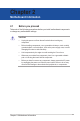
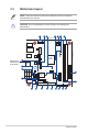
2.2 Motherboard layout
Place this side
towards the rear
of the chassis
NOTE: Place four screws into the holes indicated by circles to secure the
motherboard to the chassis.
CAUTION! Do not overtighten the screws! Doing so can damage the
motherboard.