
User Manual
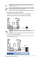
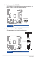
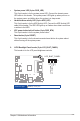
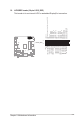
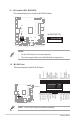
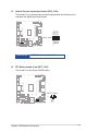
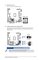
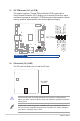
Table Of Contents
- Chapter 1 Product overview
- Chapter 2 Motherboard information
- Chapter 3 BIOS setup
- BIOS setup
- 3.1 BIOS setup program
- 3.2 Main menu
- 3.3 Advanced menu
- 3.3.1 PCH-FW Configuration
- 3.3.2 Trusted Computing
- 3.3.3 CPU Configuration
- 3.3.4 Graphics Configuration
- 3.3.5 PCI Express Configuration
- 3.3.6 Super IO Configuration
- 3.3.7 Serial Console Redirection
- 3.3.8 SATA Configuration
- 3.3.9 Network Stack Configuration
- 3.3.10 USB Configuration
- 3.3.11 NVMe Configuration
- 3.3.12 Onboard Device Configuration
- 3.3.13 APM Configuration
- 3.3.14 Watchdog Timer
- 3.3.15 EZ-Flash
- 3.3.16 LVDS Configuration
- 3.4 Hardware Monitor menu
- 3.5 Security menu
- 3.6 Boot menu
- 3.7 Exit menu
- BIOS setup
- Appendix

2-13
Chapter 2: Motherboard information
CAUTION! Never connect a 1394 cable to the USB headers. Doing so will
damage the motherboard.
NOTE: The USB cables are purchased separately.
5. SATA power connector (4-pin SATA_PWR)
This connector is for the SATA power cable. The power cable plug is
designed to t this connector in only one orientation. Find the proper
orientation and push down rmly until the connector completely ts.
SATA_PWR1
+5V
GND
GND
+12V
PIN 1
IMPORTANT: The SATA power connector supports 1A current to the
maximum.
6. SATA 6.0 Gb/s port (7-pin SATA6G)
This port connects to a SATA 6.0 Gb/s hard disk drive or an optical drive via
a SATA 6.0 Gb/s signal cable.
SATA6G
GND
RSATA_RXP
RSATA_RXN
GND
RSATA_TXN
RSATA_TXP
GND
Connector type
WAFER HD 7p, 1.27mm pitch