User Guide Motherboard K8S-MX
E1884 Checklist Revised Edition V2 December 2004 Copyright © 2004 ASUSTeK COMPUTER INC. All Rights Reserved. No part of this manual, including the products and software described in it, may be reproduced, transmitted, transcribed, stored in a retrieval system, or translated into any language in any form or by any means, except documentation kept by the purchaser for backup purposes, without the express written permission of ASUSTeK COMPUTER INC. (“ASUS”).
Contents Features Notices ........................................................................................... vi Safety information ......................................................................... vii About this guide ............................................................................ viii Conventions used in this guide ........................................... viii Typography ..........................................................................
Contents Safeguards Chapter 2: BIOS Information 2.1 2.2 2.3 2.4 2.5 iv Managing and updating your BIOS .................................... 2-2 2.1.1 Creating a bootable floppy disk ............................. 2-2 2.1.2 Using AFUDOS to update the BIOS ...................... 2-3 2.1.3 Using AFUDOS to copy BIOS from PC ................. 2-4 2.1.4 Using ASUS EZ Flash to update the BIOS ............ 2-5 2.1.5 Recovering the BIOS with CrashFree BIOS 2 ....... 2-6 BIOS Setup program .....................
Contents 2.6 2.7 2.5.8 Hardware Monitor ................................................ 2-26 Boot menu ........................................................................ 2-27 2.6.1 Boot Device Priority ............................................. 2-27 2.6.2 Hard Disk Drives .................................................. 2-27 2.6.3 Boot Settings Configuration ................................. 2-28 2.6.4 Security ................................................................ 2-29 Exit menu ...
Notices Federal Communications Commission Statement This device complies with Part 15 of the FCC Rules. Operation is subject to the following two conditions: • This device may not cause harmful interference, and • This device must accept any interference received including interference that may cause undesired operation. The use of shielded cables for connection of the monitor to the graphics card is required to assure compliance with FCC regulations.
Safety information Electrical safety • To prevent electrical shock hazard, disconnect the power cable from the electrical outlet before relocating the system. • When adding or removing devices to or from the system, ensure that the power cables for the devices are unplugged before the signal cables are connected. If possible, disconnect all power cables from the existing system before you add a device.
About this guide Conventions used in this guide To make sure that you perform certain tasks properly, take note of the following symbols used throughout this manual. WARNING: Information to prevent injury to yourself when trying to complete a task. CAUTION: Information to prevent damage to the components when trying to complete a task. IMPORTANT: Information that you MUST follow to complete a task. NOTE: Tips and additional information to aid in completing a task.
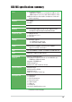
K8S-MX specifications summary CPU Socket 754 that supports: - AMD Athlon™ 64 processor with built-in 1MB L2 cache - AMD Sempron™ processor with built-in 256K L2 cache AMD 64 architecture that enables simultaneous 32-bit and 64-bit computing Chipset SiS 760GX SiS 965L System Bus 800 MHz Memory 2 x 184-pin DDR DIMM sockets for up to 2GB non-ECC PC3200/PC2700/PC2100/PC1600 DDR DIMMs Expansion slots 1 x AGP 8X/4X slot 1 x PCI Express 1x slot 2 x PCI slots Storage South Bridge supports - 2 x UltraATA
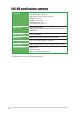
K8S-MX specifications summary Internal I/O 2 x USB 2.0 connector for 4 additional USB ports CPU/Chassis fan connectors 20-pin/4-pin ATX 12V power connectors CD/AUX connectors S/PDIF out connector GAME/MIDI connector Front panel audio connector BIOS features 4Mb Flash EEPROM AMI BIOS with enhanced ACPI, PnP, DMI, ASUS MyLogo™, SM BIOS 2.3 Industry standard PCI 2.2, USB 2.0/1.
Chapter 1 This chapter describes the features of the motherboard. It includes brief descriptions of the motherboard components, and illustrations of the layout, jumper settings, and connectors.
1.1 Welcome! Thank you for buying the ASUS® K8S-MX motherboard! The motherboard delivers a host of new features and latest technologies making it another standout in the long line of ASUS quality motherboards! The motherboard combines the powers of the AMD Athlon™ 64 or AMD Sempron™ processor and the SiS 760GX chipset to set a new benchmark for an effective desktop platform solution.
1.3 Special features 1.3.1 Product Highlights Latest processor technology The motherboard supports the AMD Athlon™ 64 and AMD Sempron™ desktop processors. The AMD Athlon™ 64 is based on AMD’s 64-bit architecture, which represents the landmark introduction of the industry’s first x86-64 technology. This processor provides a dramatic leap forward in compatibility, performance, investment protection, and reduced total cost of ownership and development.
S/PDIF out The motherboard’s S/PDIF out function turns your computer into a high-end entertainment system with digital connectivity to powerful speaker systems. USB 2.0 technology The motherboard implements the Universal Serial Bus 2.0 (USB 2.0) specification, extending the connection speed from 12 Mbps on USB 1.1 to a fast 480Mbps on USB 2.0. 6-Channel Audio solution The motherboard uses an onboard audio CODEC that lets you enjoy high-quality 6-channel audio without having to buy advanced sound cards.
1.4 Before you proceed Take note of the following precautions before you install motherboard components or change any motherboard settings. 1. Unplug the power cord from the wall socket before touching any component. 2. Use a grounded wrist strap or touch a safely grounded object or to a metal object, such as the power supply case, before handling components to avoid damaging them due to static electricity. 3. Hold components by the edges to avoid touching the ICs on them. 4.
1.5 Motherboard overview 1.5.1 Motherboard layout 19.3cm (7.6in) ® PS/2KBMS T: Mouse B: Keyboard CPU_FAN ATX12V USB12 USBPW34 USBPW12 Bottom: ATXPWR 24.4cm (9.
1.5.2 Placement direction When installing the motherboard, make sure that you place it into the chassis in the correct orientation. The edge with external ports goes to the rear part of the chassis as indicated in the image below. 1.5.3 Screw holes Place six (6) screws into the holes indicated by circles to secure the motherboard to the chassis. Do not overtighten the screws! Doing so may damage the motherboard.
1.6 Central Processing Unit (CPU) 1.6.1 Overview The motherboard comes with a surface mount 754-pin Zero Insertion Force (ZIF) socket designed for the AMD Athlon™ 64 processor. The 128-bit-wide data paths of these processors can run applications faster than processors with only 32-bit or 64-bit wide data paths.
1.6.2 Installing the CPU Follow these steps to install a CPU. 1. Locate the 754-pin ZIF socket on the motherboard. 2. Unlock the socket by pressing the lever sideways, then lift it up to a 90°-100° angle. Socket Lever Make sure that the socket lever is lifted up to 90°-100° angle, otherwise the CPU does not fit in completely. 3. Position the CPU above the socket such that the CPU corner with the gold triangle matches the socket corner with a small triangle. 4.
1.7 System memory 1.7.1 DIMM sockets location 104 Pins ® DIMM2 DIMM1 The following figure illustrates the location of the DDR DIMM sockets. 80 Pins K8S-MX K8S-MX 184-pin DDR DIMM sockets • Make sure to unplug the power supply before adding or removing DIMMs or other system components. Failure to do so may cause severe damage to both the motherboard and the components. • When installing long AGP cards, it is recommended to install the memory modules first.
Table 1 Recommended memory configurations Number of DIMMs 1 256MB 257MB 512MB 512MB 512MB 256MB 256MB 512MB 256MB 512MB 256MB 512MB 256MB 256MB 512MB 256MB 512MB 256MB 512MB 512MB 256MB 256MB 512MB 256MB 512MB 256MB 512MB 256MB 256MB 512MB 512MB 256MB 512MB 256MB 256MB DIMM Slot DIMM2 Single Side Max Speed - DDR 400 1 - Single Side DDR 400 1 Double Side - DDR 400 1 - Double Side DDR 400 2 Single Side Single Side DDR 400 2 Single Side Double Side DDR 400 2 Double Side Single Si
Table 2 Size 512MB 512MB 512MB 256MB 512MB 256MB 256MB 512MB 256MB 512MB 256MB 512MB 256MB 512MB 512MB 512MB 256MB 256MB 512MB 256MB 512MB 512MB 1G 512MB 256MB 512MB 512MB DDR400 Qualified Vendor List (QVL) Vendor Transcend Transcend Transcend Pmi Pmi Kingmax Kingmax Kingmax Kingmax Mosel Mosel Nanya Nanya Apacer Apacer Apacer Apacer Apacer Apacer Apacer Smart Smart Smart Twinmos Twinmos A Data A Data Promos Model DDR400-512 DDR400-512 DDR333-512 3208GATA07-04A7 3208GATA01-04A4 MPMB62D-38LT3R MPMC22D-38HT
1.7.3 Installing a DIMM DDR DIMM Follow these steps to install a DIMM. 1. Unlock a DIMM socket by pressing the retaining clips outward. 2. Align a DIMM on the socket such that the notch on the DIMM matches the break on the socket. 3. Firmly insert the DIMM into the socket until the retaining clips snap back in place and the DIMM is properly seated. Unlocked A DDR DIMM is keyed with a notch so that it fits in only one direction. DO NOT force a DIMM into a socket to avoid damaging the DIMM. 1.
1.8.2 IRQ assignments for this motherboard INT A shared — — — — PCI slot 1 PCI slot 2 LAN AGP slot VGA slot INT B — shared — — — INT C — — — shared shared INT D — — shared — — When using PCI cards on shared slots, ensure that the drivers support “Share IRQ” or that the cards do not need IRQ assignments. Otherwise, conflicts will arise between the two PCI groups, making the system unstable and the card inoperable. 1.8.
1.8.5 AGP slot The Accelerated Graphics Port (AGP) slot supports AGP 8X/4X (+1.5V) cards. When you buy an AGP card, make sure that you ask for one with +1.5V specification. Note the notches on the card golden fingers to ensure that they fit the AGP slot on the motherboard. Install only +1.5V AGP cards. ® K8S-MX Keyed for 1.
1.9 Jumpers 1. Clear RTC RAM (CLRTC) This jumper allows you to clear the Real Time Clock (RTC) RAM in CMOS. You can clear the CMOS memory of date, time, and system setup parameters by erasing the CMOS RTC RAM data. The RAM data in CMOS, that include system setup information such as system • words, is powered by the onboard button cell battery. To erase the RTC RAM: 1. Turn OFF the computer and unplug the power cord. 2. Move the jumper cap from pins 1-2 (default) to pins 2-3.
2. USB device wake-up (3-pin USBPW12, USBPW34, USBPW56, USBPW78) Set these jumpers to +5V to wake up the computer from S1 sleep mode (CPU stopped, DRAM refreshed, system running in low power mode) using the connected USB devices. Set to +5VSB to wake up from S3 and S4 sleep modes (no power to CPU, DRAM in slow refresh, power supply in reduced power mode).
1.10 Connectors This section describes and illustrates the motherboard rear panel and internal connectors. 1.10.1 Rear panel connectors 1 2 3 4 5 6 11 10 9 8 7 1. PS/2 mouse port. This green 6-pin connector is for a PS/2 mouse. 2. Parallel port. This 25-pin port connects a parallel printer, a scanner, or other devices. 3. RJ-45 port. This port allows connection to a Local Area Network (LAN) through a network hub. Refer to the table below for the LAN port LED indications. 4. Line In jack.
1.10.2 Internal connectors 1. IDE connectors (40-1 pin PRI_IDE, SEC_IDE) This connector supports the provided UltraATA133 IDE hard disk ribbon cable. Connect the cable’s blue connector to the primary (recommended) or secondary IDE connector, then connect the gray connector to the UltraATA133 slave device (hard disk drive) and the black connector to the UltraATA133 master device. • Follow the hard disk drive documentation when setting the device in master or slave mode.
3. ATX power connectors (20-pin ATXPWR, 4-pin ATX12V) These connectors connect to an ATX 12V power supply. The plugs from the power supply are designed to fit these connectors in only one orientation. Find the proper orientation and push down firmly until the connectors completely fit. In addition to the 20-pin ATX power connector, this motherboard requires that you connect the 4-pin ATX +12V power plug to provide sufficient power to the CPU.
5. CPU and chassis fan connectors (3-pin CPU_FAN, CHA_FAN) The fan connectors support cooling fans of 350mA~740mA (8.88W max.) or a total of 1A~2.22A (26.64W max.) at +12V. Connect the fan cables to the fan connectors on the motherboard, making sure that the black wire of each cable matches the ground pin of the connector. Do not forget to connect the fan cables to the fan connectors. Lack of sufficient air flow within the system may damage the motherboard components.
7. Front panel audio connector (10-1 pin FP_AUDIO) This is an interface for the front panel cable that allows convenient connection and control of audio devices. Be default, the pins labeled LINE OUT_R/BLINE_OUT_R and the pins LINE OUT_L/BLINE_OUT_L are shorted with jumper caps. Remove the caps only when you are connecting the front panel audio cable. Line out_L NC Line out_R MICPWR MIC2 ® BLINE_OUT_L BLINE_OUT_R +5VA AGND FP_AUDIO K8S-MX K8S-MX Front panel audio connector 8.
9. GAME/MIDI connector (16-1 pin GAME1) This connector supports a GAME/MIDI module. If a GAME/MIDI module is available, connect the GAME/MIDI cable to this connector. The GAME/MIDI port on the module connects a joystick or a game pad for playing games, and MIDI devices for playing or editing audio files. +5V J2B1 J2CX MIDI_OUT J2CY J2B2 MIDI_IN ® K8S-MX K8S-MX Game connector +5V J1B1 J1CX GND GND J1CY J1B2 +5V GAME1 The GAME/MIDI module is purchased separately. 10.
11. Digital Audio connector (6-1 pin SPDIF_OUT) This connector is for the S/PDIF audio module to allow digital sound output. Connect one end of the S/PDIF audio cable to this connector and the other end to the S/PDIF module. ® SPDIF_OUT GND SPDIFOUT K8S-MX +5V K8S-MX Digital audio connector The S/PDIF out module is purchased separately. 12. System panel connector (10-1 pin PANEL) This connector accommodates several system front panel functions.
• Reset Switch Lead (Blue 2-pin RESET) This 2-pin connector connects to the case-mounted reset switch for rebooting the system without turning off the system power. • ATX Power Switch / Soft-Off Switch Lead (Yellow 2-pin PWRSW ) This connector connects a switch that controls the system power. Pressing the power switch turns the system between ON and SLEEP, or ON and SOFT OFF, depending on the BIOS or OS settings. Pressing the power switch while in the ON mode for more than 4 seconds turns the system OFF.
1-26 Chapter 1: Product introduction
Chapter 2 This chapter tells how to change system settings through the BIOS Setup menus. Detailed descriptions of the BIOS parameters are also provided.
2.1 Managing and updating your BIOS The following utilities allow you to manage and update the motherboard Basic Input/Output System (BIOS) setup. 1. ASUS AFUDOS - Updates the BIOS using a bootable floppy disk in DOS mode. 2. ASUS EZ Flash - Updates the BIOS using a floppy disk during POST. 3. ASUS CrashFree BIOS 2 - Updates the BIOS using a bootable floppy disk or the motherboard support CD. Refer to the corresponding sections for details on these utilities.
c. Click Start, then select Run. d. From the Open box, type D:\bootdisk\makeboot a: then press , assuming that D: is your CD-ROM drive. e. Follow succeeding screen instructions. 2. Copy the original (or the latest) motherboard BIOS to the bootable floppy disk. 2.1.2 Using AFUDOS to update the BIOS To update the BIOS using the AFUDOS.EXE utility: 1. Visit the ASUS website (www.asus.com) to download the latest BIOS file for your motherboard. Save the BIOS file to a bootable floppy disk.
When the BIOS update process is complete, the utility returns to the DOS prompt. A:\>afudos /iK8S-MX.ROM AMI Firmware Update Utility - Version 1.10 Copyright (C) 2002 American Megatrends, Inc. All rights reserved. Reading file ..... Erasing flash .... Writing flash .... Verifying flash .. done done 0x0008CC00 (9%) done A:\> 5. Reboot the system from the hard disk. 2.1.3 Using AFUDOS to copy BIOS from PC You can use the AFUDOS.
3. The utility will copy the current system BIOS by default to the floppy disk. Make sure that the floppy disk has at least 600KB of free disk space and is not writeprotected. A:\>afudos /oMYBIOS03.ROM AMI Firmware Update Utility - Version 1.10 Copyright (C) 2002 American Megatrends, Inc. All rights reserved. Reading flash ..... done A:\> When the copy process is complete, the utility returns to the DOS prompt. 2.1.
DO NOT shutdown or reset the system while updating the BIOS! Doing so may cause system boot failure! User recovery requested. Starting BIOS recovery... Checking for floppy... Floppy found! Reading file “K8S-MX.ROM”. Completed. Start flashing... Flashed successfully. Rebooting. 2.1.
Bad BIOS checksum. Starting BIOS recovery... Checking for floppy... Floppy found! Reading file “K8S-MX.ROM”. Completed. Start flashing... DO NOT shut down or reset the system while updating the BIOS! Doing so may cause system boot failure! 2. When the BIOS update process is complete, reboot the system. To recover the BIOS from the support CD: 1. Boot the system. 2. When a corrupted BIOS is detected, the following screen message appears. Bad BIOS checksum. Starting BIOS recovery... Checking for floppy...
2.2 BIOS Setup program This motherboard supports a programmable LPC chip that you can update using the provided utility described in section “2.1 Managing and updating your BIOS.” Use the BIOS Setup program when you are installing a motherboard, reconfiguring your system, or prompted to “Run Setup”. This section explains how to configure your system using this utility. Even if you are not prompted to use the Setup program, you may want to change the configuration of your computer in the future.
2.2.1 BIOS menu screen Menu items Menu bar Configuration fields System Time System Date Legacy Diskette A Primary IDE Master Primary IDE Slave Secondary IDE Master Secondary IDE Slave Onboard PCI S-ATA Controller [11:51:19] [Thu 08/05/2003] [1.44M, 3.5 in] : [ST320413A] : [ASUS CD-S340] : [Not Detected] : [Not Detected] [Disabled] General help Use [ENTER], [TAB] or [SHIFT-TAB] to select a field. Use [+] or [-] to configure system time. System Information Sub-menu items Navigation keys 2.2.
2.2.4 Menu items The highlighted item on the menu bar displays the specific items for that menu. For example, selecting Main shows the Main menu items. The other items (Advanced, Power, Boot, and Exit) on the menu bar have their respective menu items. System Time System Date Legacy Diskette A Language [11:51:19] [Thu 08/05/2003] [1.44M, 3.
2.3 Main menu When you enter the BIOS Setup program, the Main menu screen appears giving you an overview of the basic system information. Refer to section “2.2.1 BIOS menu screen” for information on the menu screen items and how to navigate through them. System Time System Date Legacy Diskette A Primary IDE Master Primary IDE Slave Secondary IDE Master Secondary IDE Slave Onboard PCI S-ATA Controller [11:51:19] [Thu 08/05/2003] [1.44M, 3.
2.3.4 Primary and Secondary IDE Master/Slave While entering Setup, BIOS auto-detects the presence of IDE devices. There is a separate sub-menu for each IDE device. Select a device item then press to display the IDE device information. Primary IDE Master Device : Hard Disk Vendor : ST320413A Size : 20.
PIO Mode [Auto] Selects the PIO mode. Configuration options: [Auto] [0] [1] [2] [3] [4] DMA Mode [Auto] Selects the DMA mode. Configuration options: [Auto] [SWDMA0] [SWDMA1] [SWDMA2] [MWDMA0] [MWDMA1] [MWDMA2] [UDMA0] [UDMA1] [UDMA2] [UDMA3] [UDMA4] [UDMA5] SMART Monitoring [Auto] Sets the Smart Monitoring, Analysis, and Reporting Technology. Configuration options: [Auto] [Disabled] [Enabled] 32Bit Data Transfer [Disabled] Enables or disables 32-bit data transfer.
2.4 Advanced menu The Advanced menu items allow you to change the settings for the CPU and other system devices. Take caution when changing the settings of the Advanced menu items. Incorrect field values may cause the system to malfunction. JumperFree Configuration CPU Configuration Chipset Onboard Devices Configuration PCI PnP 2.4.1 JumperFree Configuration Configure System Frequency Overclock Option [Standard] Overclock Option [Standard] Sets the mode for overclocking.
DDR Reference Voltage [Auto] Allows you to automatically detect or select from a list the DDR operating voltage. Configuration options: [2.6V] [2.5V] [Auto] 2.4.2 CPU Configuration The items in this menu show the CPU-related information auto-detected by BIOS. GART Error Reporting MTRR Mapping [Disabled] [Continous] Cool N’Quiet Memory Configuration [Enabled] This option should remain disabled for the normal operation. The driver developer may enable it for testing purpose.
Bank Interleaving [ Disabled] Sets whether to allow memory accesses to be spread out over BANKS on the same node or across nodes, decreasing access contention. Configuration options: [Auto] [Disabled] Node Interleaving [Disabled] Sets whether to allow memory accesses to be spread out over NODES on the same node or across nodes, decreasing access contention. Configuration options: [Auto] [Disabled] Burst Length [ 8 Beats] Sets the burst length. Set to 4 beats to use 64 Bit Dq.
2.4.3 Chipset The Chipset menu items allow you to change the advanced chipset settings. Select an item then press to display the sub-menu. Chipset Settings AGP Configuration HyperTransport Configuration MPS Configuration AGP Configuration Aperture Size Graphics Adapter Priority AGP Fast Write Select AGP 3.0 Data Ratio Share Memory [64MB] [AGP/Int-VGA] [Disabled] [8X] [ 32MB] Aperture Size [64MB] Allows you to select the size of mapped memory for AGP graphic data.
HyperTransport Configuration HyperTransport Configuration HT Width HT Speed HT Tristate Enabled CRC Flood Enable [ 8x16 BIT] [800 MHz] [Disabled] [Disabled] HT Width [ 8x16 BIT] Allows selection of HyperTransport upstream data width. Configuration options: [8x8 BIT] [16x16 BIT] [16x8 BIT] [8x16 BIT] HT Speed [800 MHz] Allows frequency selection of HyperTransport transfer from K8 CPU to AGP.
2.4.4 Onboard Devices Configuration OnBoard AC’97 Audio DEVICE OnBoard SiS190 LAN DEVICE SiS190 LAN Boot ROM All PCI EXPRESS Controller All PCI EXPRESS INTPIN USB Configuration [Enabled] [Enabled] [Disabled [Enabled] [Disabled] Serial Port1 Address Parallel Port Address Parallel Port Mode ECP Mode DMA Channel Parallel Port IRQ OnBoard Game Port [3F8/IRQ4] [378] [ECP] [DMA3] [IRQ7] [Disabled] OnBoard AC’97 Audio DEVICE [Enabled] Allows the BIOS to detect whether you are using any audio device.
USB Configuration The items in this menu allows you to change the USB-related features. Select an item then press to display the configuration options. OnBoard SiS USB1.1 DEVICE OnBoard SiS USB2.0 DEVICE [Enabled] [Enabled] USB Configuration Module Version - 2.23.2-9.4 USB Devices Enabled: None Legacy USB Support USB 2.0 Controller Mode Stop EHCI HC in OHCI handover [Auto] [HiSpeed] [Enabled] OnBoard SiS USB1.1 DEVICE [Enabled] Allows you to enable or disable the onboard SiS USB 1.1 port.
Serial Port1 Address [3F8/IRQ4] Allows you to select the Serial Port1 base address. Configuration options: [Disabled] [3F8/IRQ4] [2F8/IRQ3] [3E8/IRQ4] [2E8/IRQ3] Parallel Port Address [378] Allows you to select the Parallel Port base addresses. Configuration options: [Disabled] [378] [278] [3BC] Parallel Port Mode [Normal] Allows you to select the Parallel Port mode. Configuration options: [Normal] [Bi-Directional] [EPP] [ECP] EPP Version [1.9] Appears only when the Parallel Port Mode is set to [EPP].
2.4.5 PCI PnP The PCI PnP menu items allow you to change the advanced settings for PCI/PnP devices. The menu includes setting IRQ and DMA channel resources for either PCI/PnP or legacy ISA devices, and setting the memory size block for legacy ISA devices. Take caution when changing the settings of the PCI PnP menu items. Incorrect field values may cause the system to malfunction. Advanced PCI/PnP Settings WARNING: Setting wrong values in below sections may cause system to malfunction.
Palette Snooping [Disabled] When set to [Enabled], the pallete snooping feature informs the PCI devices that an ISA graphics device is installed in the system so that the latter can function correctly. Setting to [Disabled] deactivates this feature. Configuration options: [Disabled] [Enabled] PCI IDE BusMaster [Enabled] Allows BIOS to use PCI bus mastering when reading/writing to IDE devices.
The following items appear only when the ACPI Aware O/S item is set to [Yes]. 2.5.2 Suspend Mode [S1 (POS) only] Allows you to select the ACPI state to be used for system suspend. Configuration options: [S1 (POS) Only] [S1 and S3 (STR)] [S3 Only] 2.5.3 ACPI 2.0 Support [No] Allows you to add more tables for ACPI 2.0 specifications. Configuration options: [No] [Yes] 2.5.4 ACPI APIC Support [Enabled] Enables or disables the ACPI support in the ASIC.
Power Button Mode [On/Off] Allows the system to go into On/Off mode or suspend mode when the power button is pressed. Configuration options: [On/Off] [Suspend] Hard Disk Time Out (Minute) [Disabled] Allows you to select the specified time in minute at which the hard disk goes on standby mode.
2.5.8 Hardware Monitor CPU Temperature Hardware Monitor CPU Temperature MB Temperature [40.5ºC/102.5ºF] [33ªC/91ºF] CPU Fan Speed Chassis Fan Speed [3260RPM] [N/A] VCORE Voltage 3.3V Voltage 5V Voltage 12V Voltage [ 1.504V] [ 3.360V] [ 5.160V] [11.328V] CPU Temperature [xxx ºC/xxx ºF] MB Temperature [xxx ºC/xxx ºF] The onboard hardware monitor automatically detects and displays the motherboard and CPU temperatures. Select Disabled if you do not wish to display the detected temperatures.
2.6 Boot menu The Boot menu items allow you to change the system boot options. Select an item then press to display the sub-menu. Boot Settings Specifies the Boot Device Priority sequence. Boot Device Priority Boot Settings Configuration Security 2.6.
2.6.3 Boot Settings Configuration Boot Settings Configuration Quick Boot Full Screen Logo AddOn ROM Display Mode Bootup Num-Lock PS/2 Mouse Support Wait for ‘F1’ If Error Hit ‘DEL’ Message Display Interrupt 19 Capture Allows BIOS to skip certain tests while booting. This will decrease the time needed to boot the system.
Interrupt 19 Capture [Disabled] When set to [Enabled], this function allows the option ROMs to trap Interrupt 19. Configuration options: [Disabled] [Enabled] 2.6.4 Security The Security menu items allow you to change the system security settings. Select an item then press to display the configuration options. Security Settings Supervisor Password User Password : Not Installed : Not Installed to change password. again to disable password.
to change password. again to disabled password. Security Settings Supervisor Password User Password : Installed : Not Installed Change Supervisor Password User Access Level Change User Password Clear User Password Password Check Boot Sector Virus Protection [Full Access] [Setup] [Disabled] User Access Level (Full Access] Allows you to select the access restriction to the Setup items.
2.7 Exit menu The Exit menu items allow you to load the optimal or failsafe default values for the BIOS items, and save or discard your changes to the BIOS items. Exit Options Exit & Save Changes Exit & Discard Changes Discard Changes Exit system setup after saving the changes. F10 key can be used for this operation. Load Setup Defaults Pressing does not immediately exit this menu. Select one of the options from this menu or from the legend bar to exit.
2-32 Chapter 2: BIOS Setup
Chapter 3 This chapter describes the contents of the support CD that comes with the motherboard package.
3.1 Install an operating system This motherboard supports Windows® 98SE/ME/2000/XP operating system (OS). Always install the latest OS version and corresponding updates to maximize the features of your hardware. Motherboard settings and hardware options vary, so use the setup procedures presented in this chapter for general reference only. Refer to your OS documentation for more information. 3.
3.2.2 Drivers menu The drivers menu shows the available device drivers if the system detects installed devices. Install the necessary drivers to activate the devices. AGP SiS 760 driver Installs the SiS 760 AGP driver. SIS 760 Graphics Driver Installs the SiS 760GX graphics controller driver. AD1888 SoundMAX Audio Driver Installs the ADI 1888 AC’97 compliant audio controller and application. SIS RAID Controller Driver Installs the SIS RAID controller driver.
3.2.3 Utilities menu The Utilities menu shows the applications and other software that the motherboard supports. ASUS AMD Cool’n’Quiet Software Installs the AMD® Cool ‘n’ Quiet! Technology software. ASUS PC Probe This smart utility monitors the fan speed, CPU temperature, and system voltages, and alerts you on any detected problems. This utility helps you keep your computer at a healthy operating condition.
3.2.4 Manuals The Manuals menu contains a list of supplementary user manuals. Click item to open the folder of the user manual. The user manual files are in Portable Document Format (PDF). Install the Adobe® Acrobat® Reader from the Utilities menu before opening a user manual file. 3.2.5 ASUS Contact Information Clicking the ASUS Contact Information tab displays as stated. You may also find this information on the inside front cover of this user guide.
3.3 RAID configurations The SIS 965L southbridge comes with a RAID controller that allows you to configure Serial ATA hard disk drives as RAID sets. The motherboard supports the following RAID configurations. RAID 0 (Data striping) optimizes two identical hard disk drives to read and write data in parallel, interleaved stacks. Two hard disks perform the same work as a single drive but at a sustained data transfer rate, double that of a single disk alone, thus improving data access and storage.
3.3.2 SIS RAID configurations The motherboard includes a high performance Serial ATA RAID controller integrated in the SIS 965L southbridge chipset. It supports RAID 0 and RAID 1 with two independent Serial ATA channels. Entering the SIS RAID BIOS utility 1. Boot your computer. 2. During POST, press + to enter the SIS RAID configuration utility. The following menu options appear. 3. Press to display the RAID setup menu. Create an Array 1.
Creating JBOD 1. From the RAID Setup, press <1> then to select JBOD (Spanning) 2. Select <1> to auto-create a RAID array or press <2> to manually configure array then press . 3. If you selected 1 proceed to step 5. 4. Use the up/down arrow keys to move the selection bar, then press to select a disk drive.
5. The current RAID set is displayed on the upper side of the screen. 6. Press to exit the RAID setup. 7. Press then to save changes. 8 After the setup is complete, you can partition and format your hard disk as a single hard drive.
Creating RAID 0 for performance 1. From the RAID Setup, press <2> then to select RAID 0 (Striping). 2. Select <1> to auto-create a RAID array or press <2> to manually configure array then press . 3. If you selected 1 proceed to step 7. 4. If you selected 2, select the array block size by pressing the corresponding number beside the available block sizes then press .
5. Use the up/down arrow keys to move the selection bar, then press to select a disk drive. 6. After selecting the drives, press to return to previous menu. 7. Press then to create a Stripe only configuration. Press if you wish to split the data on the source disk to other disks. 8. If you selected Y, the following screen appears. 9. When finished, press to return to previous menu.
10. The current RAID setup is displayed on the upper side of the screen. Press to exit the RAID setup menu. 11. Press then to save changes. 12. When finished, you can partition and format the array as a single hard drive.
Creating RAID 1 for capacity 1. From the RAID Setup, press <3> then to select RAID 1 (Mirroring). 2. Select <1> to auto-create a RAID array or press <2> to manually configure array then press . 3. If you selected 1 proceed to step 5. 4. Use the up/down arrow keys to move the selection bar, then press to select a disk drive.
5. Press then to create a mirrored set. Press if you wish to duplicate the source disk (DISK 1) data to the RAID disks. 6. If you selected Y, the followig screen appears. 7. When finished, press to return to previous menu. The current RAID set is displayed on the upper side of the screen.
8. Press to exit the RAID setup. 9. Press then to save changes. 10. After the setup is complete, you can partition and format the array as a single hard drive.
3.4 Creating a RAID driver disk A floppy disk with the RAID driver is required when installing Windows® 2000/XP operating system on a hard disk drive that is included in a RAID set. Use the support CD that came with the motherboard package to create a RAID driver disk. To use the support CD: 1. Boot your computer. 2. Press during POST to enter the BIOS setup utility. 3. Set the optical drive as the primary boot device. 4. Save changes and exit BIOS. 5. Insert the support CD into the optical drive.