User Guide Motherboard K8V-VM
E2611 First Edition May 2006 Copyright © 2006 ASUSTeK COMPUTER INC. All Rights Reserved. No part of this manual, including the products and software described in it, may be reproduced, transmitted, transcribed, stored in a retrieval system, or translated into any language in any form or by any means, except documentation kept by the purchaser for backup purposes, without the express written permission of ASUSTeK COMPUTER INC. (“ASUS”).
Contents Notices............................................................................................. vi Safety information........................................................................... vii K8V-VM specifications summary....................................................viii Chapter 1: Product Introduction 1.1 1.2 1.3 Welcome!..............................................................................1-2 Package contents...............................................................
Contents Chapter 2: BIOS Information 2.1 2.2 2.3 2.4 2.5 2.6 2.7 iv Managing and updating your BIOS.......................................2-2 2.1.1 Creating a bootable floppy disk................................2-2 2.1.2 Using AFUDOS to copy the current BIOS................2-2 2.1.3 Using AFUDOS to update the BIOS.........................2-3 2.1.4 ASUS CrashFree BIOS 2 utility................................2-5 2.1.5 Using ASUS EZ Flash to update the BIOS..............2-7 BIOS Setup program.........
Contents Chapter 3: Software Support 3.1 3.2 Installing an operating system..............................................3-2 Support CD information........................................................3-2 3.2.1 Running the support CD...........................................3-2 3.2.2 Drivers menu............................................................3-3 3.2.3 Utilities menu............................................................3-3 3.2.4 Make disk menu...........................................
Notices Federal Communications Commission Statement This device complies with Part 15 of the FCC Rules. Operation is subject to the following two conditions: • This device may not cause harmful interference, and • This device must accept any interference received including interference that may cause undesired operation. This equipment has been tested and found to comply with the limits for a Class B digital device, pursuant to Part 15 of the FCC Rules.
Safety Information Electrical safety • To prevent electrical shock hazard, disconnect the power cable from the electrical outlet before relocating the system. • When adding or removing devices to or from the system, ensure that the power cables for the devices are unplugged before the signal cables are connected. If possible, disconnect all power cables from the existing system before you add a device.
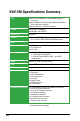
K8V-VM Specifications Summary CPU Socket 754 for AMD Athlon™ 64 and AMD Sempron™ processors Supports AMD 64 architecture that enables simultaneous 32-bit and 64-bit computing Supports AMD Cool ‘n’ Quiet! Technology Chipset Northbridge: VIA K8M890 Southbridge: VIA VT8237A System bus 1600 MT/s Memory 2 x 184-pin DDR DIMM sockets for up to 2 GB unbuffered ECC, non-ECC DDR 400/333/266 DRAM memory VGA Integrated Gfx in North bridge Expansion slots 1 x PCI Express x16 slot for
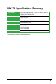
K8V-VM Specifications Summary BIOS features 4Mb Flash ROM, AMI BIOS, (TCAV), PnP, DMI2.0, WfM2.0, SM BIOS 2.3, PXE Boot BIOS ASUS special features ASUS MyLogo ASUS EZ Flash ASUS CrashFree BIOS 2 Manageability WOL/WOR by PME, WOR by Ring, WO USB, WO PS/2 Keyboard/Mouse, PXE Support CD Device drivers ASUS PC Probe II Anti-Virus Software ASUS LiveUpdate Form factor MicroATX 9.6” x 7.2” (24.5cm x 19.2cm) *Specifications are subject to change without notice.
Chapter 1 This chapter describes the features of this motherboard. It includes brief explanations of the special attributes of the motherboard and the new technology it supports.
1.1 Welcome! Thank you for buying the ASUS ® K8V-VM motherboard! The ASUS K8V-VM motherboard delivers a host of new features and latest technologies making it another standout in the long line of ASUS quality motherboards! Before you start installing the motherboard, and hardware devices on it, check the items in your package with the list below. 1.2 Package Contents Check your K8V-VM package for the following items.
VIA K8M890 and VT8237A chipset The VIA K8M890 northbridge is a 64-bit processor controller that utilizes the HyperTransport™ bus link to interconnect with the AMD AthlonTM 64 and AMD Sempron TM processors. The VIA K8M890 features an Integrated Graphics Processor (IGP) to deliver exceptional integrated graphics and video playback performance.
1.3.2 ASUS unique features EZ Flash BIOS With the ASUS EZ Flash, you can easily update the system BIOS even before loading the operating system. No need to use a DOS-based utility or boot from a floppy disk. See page 2-7. CrashFree BIOS2 Whenever BIOS gets corrupted, ASUS CrashFree BIOS2 allows users to reboot the computer and perform an smart auto-recovery procedure through the motherboard support CD. See page 2-5.
1.4 Before You Proceed Take note of the following precautions before you install motherboard components or change any motherboard settings. • Unplug the power cord from the wall socket before touching any component. • Use a grounded wrist strap or touch a safely grounded object or a metal object, such as the power supply case, before handling components to avoid damaging them due to static electricity. • Hold components by the edges to avoid touching the ICs on them.
1.5 Motherboard Overview 1.5.1 Motherboard layout PS/2KBM T: Mouse B: Keyboard CPU_FAN 18.2cm (7.2in) ATX12V Bottom: PCI1 USB56 AAFP PRI_IDE 4M BIOS SEC_IDE CR2032 3V Lithium Cell CMOS Power PCIEX16 Super I/O RTL8201CL R PCIEX1_1 PCI2 FLOPPY VIA VT8237A USB78 SPEAKER CLRTC CHA_FAN Top:Line In Center:Line Out Below:Mic In ALC660 SB_PWR F_PANEL SATA1 1- EATXPWR VIA K8M890 Top: USB3 RJ-45 USB4 24.5cm (9.
1.5.2 Placement direction When installing the motherboard, make sure that you place it into the chassis in the correct orientation. The edge with external ports goes to the rear part of the chassis as indicated in the image below. 1.5.3 Screw holes Place six (6) screws into the holes indicated by circles to secure the motherboard to the chassis. Place this side towards the rear of the chassis K8V-VM Do not overtighten the screws! Doing so may damage the motherboard.
1.6 Central Processing Unit (CPU) 1.6.1 Overview The motherboard comes with a surface mount 754-pin Zero Insertion Force (ZIF) socket designed for the AMD Athlon™ 64 processor. K8V-VM The AMD Athlon™ 64 processor has a gold triangle at one corner. This mark indicates the processor Pin A1 that should match a specific corner of the CPU socket. R r K8V-VM CPU Socket 7 4 Incorrect installation of the CPU into the socket may bend the pins and severely damage the CPU! 1.6.
3. Position the CPU above the socket such that the CPU corner with the gold triangle matches the socket corner with a small triangle. 4. Carefully insert the CPU into the socket until it fits in place. Gold triangle The CPU fits only in one correct orientation. DO NOT force the CPU into the socket to prevent bending the pins and damaging the CPU! 5. When the CPU is in place, push down the socket lever to secure the CPU. The lever clicks on the side tab to indicate that it is locked. 6.
1.7 System memory 1.7.1 Overview The motherboard comes with two Double Data Rate (DDR) Dual Inline Memory Module (DIMM) sockets. These sockets support up to 2GB system memory using 184-pin PC3200/PC2700/PC2100 unbuffered DDR DIMMs and allow up to 3.2 GB/s data transfer rate. DIMM2 K8V-VM DIMM1 The following figure illustrates the location of the DDR DIMM sockets. R r K8V-VM 184-pin DDR DIMM sockets 1.7.
Qualified DDR400 DIMMs The following table lists the DDR400 (PC3200) memory modules that have been tested and qualified for use with this motherboard. Obtain DDR DIMMs only from qualified vendors for better system performance.
DDR400 Qualified Vendors List Size Vendor Model Brand Side(s) Component 512MB 256MB 512MB 256MB 256MB 512MB 256MB 512MB 256MB 512MB 512MB 1G 256MB 256MB 512MB 512MB 256MB 256MB 256MB 512MB 512MB 256MB 256MB 512MB 512MB 512MB 512MB 512MB Kingmax Kingmax Kingmax Vdata Pmi Pmi Mosel Mosel Nanya Nanya Nanya Nanya Smart Smart Smart Smart Twinmos Twinmos Promos Promos BiaoXing Winbond Winbond Winbond Winbond Patriot MDT GEIL MPMC22D-38HT3R MPXB62D-38KT3R MPXC22D-38KT3R MDYVD6F4G2880B1E0H 3208GAT
1.7.3 Installing a DIMM Make sure to unplug the power supply before adding or removing DIMMs or other system components. Failure to do so may cause severe damage to both the motherboard and the components. Follow these steps to install a DIMM. 1. Locate the DIMM sockets in the motherboard. DDR DIMM notch 2. Unlock a DIMM socket by pressing the retaining clips outward. 3. Align a DIMM on the socket such that the notch on the DIMM matches the break on the socket.
1.8 Expansion slots In the future, you may need to install expansion cards. The following sub‑sections describe the motherboard slots and the expansion cards that they support. Make sure to unplug the power cord before adding or removing expansion cards. Failure to do so may cause you physical injury and damage motherboard components. 1.8.1 Installing an expansion card Follow these steps to install an expansion card. 1.
Standard Interrupt Assignments IRQ Priority 0 1 2 3 4* 5* 6 7* 8 9* 10* 11* 12* 13 14* 15* 1 2 N/A 11 12 13 14 15 3 4 5 6 7 8 9 10 Standard Function System Timer Keyboard Controller Programmable Interrupt Communications Port (COM2) Communications Port (COM1) Sound Card (sometimes LPT2) Floppy Disk Controller Printer Port (LPT1) System CMOS/Real Time Clock ACPI Mode when used IRQ Holder for PCI Steering IRQ Holder for PCI Steering PS/2 Compatible Mouse Port Numeric Data Processor Primary IDE Channel S
1.8.3 PCI slots The PCI slots support LAN, SCSI, USB, and other PCI cards that comply with PCI specifications. The figure shows a LAN card installed on a PCI slot. 1.8.4 PCI Express x1 slot This motherboard supports PCI Express x1 network cards, SCSI cards and other cards that comply with the PCI Express specifications. The figure shows a network card installed on the PCI Express x1 slot. 1.8.
1.9 Jumpers 1. Clear RTC RAM (CLRTC) This jumper allows you to clear the Real Time Clock (RTC) RAM in CMOS. You can clear the CMOS memory of date, time, and system setup parameters by erasing the CMOS RTC RAM data. The RAM data in CMOS, that include system setup information such as system passwords, is powered by the onboard button cell battery. To erase the RTC RAM: 1. Turn OFF the computer and unplug the power cord. 3. Move the jumper cap from pins 1-2 (default) to pins 2-3.
2. USB device wake-up (3-pin PS2_USB_PWR) Set this jumper to +5V to wake up the computer from S1 sleep mode (CPU stopped, DRAM refreshed, system running in low power mode) using the connected USB devices. Set to +5VSB to wake up from S3 and S4 sleep mode (no power to CPU, DRAM in slow refresh, power supply in reduced power mode).
1.10 Connectors This section describes and illustrates the rear panel and internal connectors on the motherboard. 1.10.1 Rear panel connectors 1 2 3 4 5 6 11 10 9 8 7 1. PS/2 mouse port (green). This 6-pin port is for a PS/2 mouse. 2. Parallel port. This 25-pin port connects a parallel printer, a scanner, or other devices. 3. LAN (RJ-45) port. This port allows connection to a Local Area Network (LAN) through a network hub. 4. Line In port.
7. USB 2.0 ports 3 and 4. These two 4-pin Universal Serial Bus (USB) ports are available for connecting USB 2.0 devices. 8. USB 2.0 ports 1 and 2. These two 4-pin Universal Serial Bus (USB) ports are available for connecting USB 2.0 devices 9. Video Graphics Adapter port. This 15-pin port is for a VGA monitor or other VGA-compatible devices. 10. Serial port. This 9-pin COM1 port is for pointing devices or other serial devices. 11. PS/2 keyboard port (purple). This port is for a PS/2 keyboard. 1.10.
2. IDE connectors (40-1 pin PRI_IDE, SEC_IDE) The onboard IDE connectors are for Ultra DMA 133/100/66 signal cables. There are three connectors on each Ultra DMA 133/100/66 signal cable: blue, black, and gray. Connect the blue connector to the motherboard’s IDE connector, then select one of the following modes to configure your device(s).
3. Internal audio connector (4-pin CD) K8V-VM This connector allows you to receive stereo audio input from sound sources such as a CD-ROM, TV tuner, or MPEG card. CD (black) Right Audio Channel CD_GND CD_GND Left Audio Channel R r K8V-VM Internal Audio Connector 4. CPU and chassis fan connectors (3-pin CPU_FAN, CHA_FAN) The fan connectors support cooling fans of 350mA~740mA (8.88W max.) or a total of 1A~2.22A (26.64W max.) at +12V.
5. ATX power connectors (24-pin EATXPWR, 4-pin ATX12V) These connectors are for ATX power supply plugs. The plugs from the power supply are designed to fit these connectors in only one orientation. Find the proper orientation and push down firmly until the connectors fit completely. • Do not forget to connect the 4-pin ATX +12V power plug; otherwise, the system does not boot up.
7. Serial ATA connectors (7-pin SATA1, SATA2) r GND RSATA_TXP2 RSATA_TXN2 GND RSATA_RXP2 RSATA_RXN2 GND R SATA2 SATA1 GND RSATA_TXP1 RSATA_TXN1 GND RSATA_RXP1 RSATA_RXN1 GND K8V-VM These connectors support the thin Serial ATA cables for Serial ATA hard disks. If you installed Serial ATA hard disks, you may create a RAID 0, RAID 1, or JBOD configuration. K8V-VM SATA Connectors 8.
9. USB connectors (10-1 pin USB56, USB78) These connectors are for USB 2.0 ports. Connect the USB module cable to any of these connectors, then install the module to a slot opening at the back of the system chassis. These USB connectors comply with USB 2.0 specification that supports up to 480 Mbps connection speed. USB+5V USB_P6USB_P6+ GND NC r USB78 1 USB+5V USB_P5USB_P5+ GND USB56 1 USB+5V USB_P7USB_P7+ GND R K8V-VM USB 2.
10. System panel connector (10-1 pin F_PANEL) This connector supports several system chassis-mounted functions. PLED+ PLEDPWR GND K8V-VM PLED PWRSW IDELED+ IDELEDGround Reset F_PANEL R r HD LED RESET K8V-VM System Panel Connector • • • • 1-26 System power LED (2-pin PLED) This 3-pin connector is for the system power LED. Connect the chassis power LED cable to this connector. The system power LED lights up when you turn on the system power, and blinks when the system is in sleep mode.
Chapter 2 This chapter tells how to change system settings through the BIOS Setup menus, and provides detailed descriptions of the BIOS parameters.
2.1 Managing and Updating Your BIOS The following utilities allow you to manage and update the motherboard Basic Input/Output System (BIOS) setup. 1. AFUDOS (Updates the BIOS in DOS mode using a bootable floppy disk.) 2. ASUS EZ Flash (Updates the BIOS using a floppy disk during POST.) 3. ASUS CrashFree BIOS2 (Updates the BIOS using a bootable floppy disk or the motherboard support CD). Refer to the corresponding section for each utility.
The BIOS information on the screen is for reference only. What you see on your screen may not be exactly the same as shown. Main filename Extension name A:\>afudos /oMYBIOS03.rom AMI Firmware Update Utility - Version 1.10 Copyright (C) 2002 American Megatrends, Inc. All rights reserved. Reading flash ..... 0x0008CC00 (9%) 2. The utility will copy the current system BIOS by default to the floppy disk.
4. At the DOS prompt, type the command line: afudos /i[filename.rom] where [filename.rom] means the latest (or original) BIOS file that you copied to the bootable floppy disk. 5. Press . The screen displays the status of the update process. The BIOS information on the screen is for reference only. What you see on your screen may not be exactly the same as shown. A:\>afudos /iK8VVM.rom AMI Firmware Update Utility - Version 1.10 Copyright (C) 2002 American Megatrends, Inc. All rights reserved.
2.1.4 ASUS CrashFree BIOS2 utility The ASUS CrashFree BIOS2 is an auto recovery tool that allows you to restore the BIOS file when it fails or gets corrupted during the updating process. You can update a corrupted BIOS file using the motherboard support CD or the floppy disk that contains the updated BIOS file. • Prepare the motherboard support CD or the floppy disk containing the updated motherboard BIOS before using this utility.
Recovering the BIOS from the support CD To recover the BIOS from the support CD: 1. Remove any floppy disk from the floppy drive, then turn on the system. 2. Insert the support CD to the optical drive. 3. The utility displays the following message and automatically checks the floppy disk for the original or updated BIOS file. Bad BIOS checksum. Starting BIOS recovery... Checking for floppy...
2.1.5 Using ASUS EZ Flash to update the BIOS The ASUS EZ Flash feature allows you to easily update the BIOS without having to go through the long process of booting from a floppy disk and using a DOS-based utility. The EZ Flash is built-in the BIOS LPC chip so it is accessible by simply pressing + during the Power-On Self -Test (POST). To update the BIOS using ASUS EZ Flash: 1. Visit the system builder website to download the latest BIOS file for your motherboard and rename it to K8VVM.ROM.
2.2 BIOS Setup Program The BIOS software is constantly being updated so the BIOS setup screens and descriptions in this section are for reference purposes only, and may not exactly match what you see on your screen. This motherboard supports a programmable Low Pin Count (LPC) chip that you can update using the provided utility described in section “2.1 Managing and updating your BIOS.” Use the BIOS Setup program when you are installing a motherboard, reconfiguring your system, or prompted to “Run Setup”.
2.2.1 BIOS menu screen Menu items Menu bar System Time System Date Legacy Diskette A Primary IDE Master Primary IDE Slave Seconday IDE Master Secondary IDE Slave Third IDE Master Third IDE Slave Fourth IDE Master Fourth IDE Slave IDE Configuration Configuration fields General help [17:08:35] [Mon 04/19/2004] [1.44M, 3.5 in.] Use [ENTER], [TAB] or [SHIFT-TAB] to select a field.
2.2.4 Menu items The highlighted item on the menu bar displays the specific items for that menu. For example, selecting Main shows the Main menu items. The other items (Advanced, Power, Boot, and Exit) on the menu bar have their respective menu items. 2.2.5 Sub-menu items A solid triangle before each item on any menu screen means that the item has a sub-menu. To display the sub-menu, select the item, then press . 2.2.6 Configuration fields These fields show the values for the menu items.
2.3 Main Menu When you enter the BIOS Setup program, the Main menu screen appears, giving you an overview of the basic system information. Refer to section “2.2.1 BIOS menu screen” for information on the menu screen items and how to navigate through them. System Time System Date Legacy Diskette A Primary IDE Master Primary IDE Slave Seconday IDE Master Secondary IDE Slave Third IDE Master Third IDE Slave Fourth IDE Master Fourth IDE Slave IDE Configuration [17:08:35] [Mon 04/19/2004] [1.44M, 3.5 in.
2.3.4 Primary, Secondary, Third, Fourth IDE Master/Slave While entering Setup, BIOS automatically detects the presence of IDE devices. There is a separate sub-menu for each IDE device. Select a device item then press to display the IDE device information. Primary IDE Master Device : Hard Disk Vendor : ST340014A Size : 40.
DMA Mode [Auto] Selects the DMA mode. Configuration options: [Auto] [SWDMA0] [SWDMA1] [SWDMA2] [MWDMA0] [MWDMA1] [MWDMA2] [UDMA0] [UDMA1] [UDMA2] [UDMA3] [UDMA4] [UDMA5] [UDMA6] SMART Monitoring [Auto] Sets the Smart Monitoring, Analysis, and Reporting Technology. Configuration options: [Auto] [Disabled] [Enabled] 32Bit Data Transfer [Enabled] Enables or disables 32-bit data transfer. Configuration options: [Disabled] [Enabled] 2.3.
2.3.6 System Information This menu gives you an overview of the general system specifications. The items in this menu are auto-detected by the BIOS. AMI BIOS Version Build Date Processor Type Speed Count : 0202 : 03/23/06 : AMD Athlon(tm) 64 Procssor 3200+ : 2000 MHz : 1 System Memory Installed Size : 256MB Usable Size : 192MB AMI BIOS Displays the auto-detected BIOS information. Processor Displays the auto-detected CPU specification System Memory Displays the auto-detected system memory.
2.4 Advanced menu The Advanced menu items allow you to change the settings for the CPU and other system devices. Take caution when changing the settings of the Advanced menu items. Incorrect field values can cause the system to malfunction. Configure CPU. CPU Configuration Chipset Onboard Devices Configuration PCIPnP ←→ ↑↓ Enter F1 F10 ESC Select Screen Select Item Go to Sub Screen General Help Save and Exit Exit V02.54 (C)Copyright 1985-2003, American Megatrends, Inc. 2.4.
GART Error Reporting [Disabled] Enables or disables the GART error reporting feature. Configuration options: [Disabled] [Enabled] MTRR Mapping [Continuous] Determines the method used for programming CPU MTRRs when using over 4G of system memory. Configuration options: [Continuous] [Discrete] 2.4.2 Chipset The Chipset menu allows you to change the advanced chipset settings. Select an item then press to display the sub-menu.
NorthBridge Configuration NorthBridge Chipset Configuration Memory Configuration ECC Configuration Memory CLK CAS Latency(Tcl) RAS/CAS Delay(Trcd) Min Active RAS(Tras) Row Precharge Time(Trp) RAS/RAS Delay(Trrd) Row Cycle (Trc) Row Refresh Cycle(Trfc) Read Write Delay(Trwt) Read Preamble Asynchronous Latency : : : : : : : : : : : 200 MHz 2.5 3 CLK 8 CLK 3 CLK 2 CLK 11 CLK 24 CLK 3 CLK 5.
Memclock Mode [Auto] Sets the memory clock mode. Configuration options: [Auto] [Limit] The following item appears when the Memclock Mode item is set to [Limit]. Memclock Value [100MHz] Configuration options: [100MHz] [133MHz] [166MHz] [183MHz] [200MHz] [216MHz] [233MHz] [250MHz] MCT Timing Mode [Auto] Sets the MCT Timing mode. Configuration options: [Auto] [Manual] The following item appears when the MCT Time Mode item is set to [Manual]. CAS Latency (CL) [Auto] Configuration options: [Auto] [2.0] [3.
CMD-ADDR Timing Mode [2T] Configuration options: [1T] [2T] Burst Length [4 Beats] Sets the operating burst length. Configuration options: [8 Beats] [4 Beats] [2 Beats] Software Memory Hole [Enabled] Enables or disables the software memory hole. Configuration options: [Disabled] [Enabled] DDR Reference Voltage [Auto] Sets the DDR reference voltage. Configuration options: [Auto] [2.6V] [2.
DRAM BG SCRUB [Disabled] Disables or sets the DRAM BG SCRUB. Configuration options: [Disabled] [40ns] [80ns] [160ns] [320ns] [640ns] [1.28us] [2.56us] [5.12us] [10.2us] [20.5us] [41.0us] [81.9us] [163.8us] [327.7us] [655.4us] [1.31ms] [2.62ms] [5.24ms] [10.49ms] [20.97ms] [42.00ms] [84.00ms] L2 Cache BG Scrub [Disabled] Disables or sets the L2 Cache BG Scrub. Configuration options: [Disabled] [40ns] [80ns] [160ns] [320ns] [640ns] [1.28us] [2.56us] [5.12us] [10.2us] [20.5us] [41.0us] [81.9us] [163.
SouthBridge Configuration Serial ATA IDE Controller [IDE] LAN Controller [Enabled] LAN BOOTROM [Disabled] High Definition Audio [Auto] USB 1.1 Ports Configuration [USB 8 Ports] Lagacy USB Support [Enabled] USB 2.0 Ports Enable [Enable] Options Disabled IDE RAID PCI Delay Transaction [Enabled] Serial ATA IDE Controller [IDE] This option allows you to set the Serial ATA IDE controller mode.
Hyper Transport Geforce 6100 Configuration LDT to AGP Lokar Frequency LDT to AGP Width (Upstream) LDT to AGP Width (Downstream) [Auto] [16 BIT] [16 BIT] LDT to AGP Lokar Frequency [Auto] Configuration options: [Auto] [200MHz] [400MHz] [600MHz] [800MHz] LDT to AGP Width (Upstream) [16 BIT] Configuration options: [16 BIT] [8 BIT] LDT to AGP Width (Downstream) [16 BIT] Configuration options: [16 BIT] [8 BIT] AMD Cool ‘N Quiet Configuration AMD Cool’N’Quiet Configuration Cool’N’ Quiet [Disabled] Enabled
2.4.3 Onboard Devices Configuration Configure Win627EHF Super IO Chipset Serial Port Address Serial Port Mode Parallel Port Address Parallel Port Mode ECP Mode DMA Channel Parallel Port IRQ [2F8/IRQ3] [Normal] [378] [ECP] [DMA3] [IRQ7] Allows BIOS to Select Serial Port Base Addresses. v02.58 (C)Copyright 1985-2004, American Megatrends, Inc. Serial Port Address [2F8/IRQ3] Allows you to select the Serial Port2 base address.
2.4.4 PCI PnP The PCI PnP menu items allow you to change the advanced settings for PCI/PnP devices. The menu includes setting IRQ and DMA channel resources for either PCI/PnP or legacy ISA devices. Take caution when changing the settings of the PCIPnP menu items. Incorrect field values can cause the system to malfunction. Advanced PCI/PnP settings WARNING: Setting wrong values in the sections below may cause system to malfunction.
2.5 Power menu The Power menu items allow you to change the power settings. Select an item then press to display the configuration options. ACPI 2.0 Support [Yes] ACPI APIC Support [Enabled] Select the ACPI state used for System Suspend. APM Configuration Hardware Monitor ←→ ↑↓ +F1 F10 ESC Select Screen Select Item Change Option General Help Save and Exit Exit v02.54 (C)Copyright 1985-2003, American Megatrends, Inc. 2.5.1 ACPI 2.
2.5.3 APM Configuration Power Management/APM [Enabled] Power Button Mode [On/Off] Restore on AC Power Loss [Power Off] Advanced Resume Events Controls Resume On Ring [Disabled] Resume On LAN [Disabled] Resume On PME# [Disabled] Resume On KBC [Disabled] Resume On PS/2 Mouse [Disabled] Resume On RTC Alarm [Disabled] Enable or disable the Advanced Power Management (APM) feature. ←→ ↑↓ +F1 F10 ESC Select Screen Select Item Change Field General Help Save and Exit Exit v02.
ResumeOn KBC [Disabled] Allows you to use specific keys on the keyboard to turn on the system. When set to [S5], the item Wake-up Key is enabled. This feature requires an ATX power supply that provides at least 1A on the +5VSB lead. Configuration options: [Disabled] [Enabled] Resume On PS/2 Mouse [Disabled] When set to [Enabled], this parameter allows you to use the PS/2 mouse to resume the system. This feature requires an ATX power supply that provides at least 1A on the +5VSB lead.
2.5.4 Hardware Monitor CPU Temperature [37.5°C/99.5°F] CPU Fan Speed Chassis Fan Speed [3214RPM] [N/A] VCORE Voltage 3.3V Voltage 5V Voltage 12V Voltage [1.424V] [3.328V] [5.232V] [11.668V] CPU Temperature ←→ ↑↓ +F1 F10 ESC Select Screen Select Item Change Option General Help Save and Exit Exit v02.54 (C)Copyright 1985-2003, American Megatrends, Inc. CPU Temperature [xxx°C/xxx°F] The onboard hardware monitor automatically detects and displays the CPU and motherboard temperatures.
2.6 Boot menu The Boot menu items allow you to change the system boot options. Select an item then press to display the sub-menu. Boot Settings Boot Device Priority Boot Settings Configuration Security Specifies the Boot Device Priority sequence. A virtual floppy disk drive (Floppy Drive B: ) may appear when you set the CD-ROM drive as the first boot device. ←→ ↑↓ Enter F1 F10 ESC Select Screen Select Item Go to Sub Screen General Help Save and Exit Exit v02.
2.6.1 Boot Device Priority Boot Device Priority 1st Boot Device 2nd Boot Device 3rd Boot Device [1st FLOPPY DRIVE] [PM-ST340014A] [SM-ASUS DVD-E616P2] Specifies the boot sequence from the available devices. A device enclosed in parenthesis has been disabled in the corresponding type menu. 1st ~ xxth Boot Device [1st FLOPPY DRIVE] These items specify the boot device priority sequence from the available devices.
2.6.2 Boot Settings Configuration Boot Settings Configuration Quick Boot Full Screen Logo AddOn ROM Display Mode Bootup Num-Lock PS/2 Mouse Support Wait for ‘ F1’ If Error Hit ‘ DEL’ Message Display Interrupt 19 Capture [Enabled] [Enabled] [Force BIOS] [On] [Auto] [Enabled] [Enabled] [Disabled] Allows BIOS to skip certain tests while booting. This will decrease the time needed to boot the system. ←→ ↑↓ +F1 F10 ESC Select Screen Select Item Change Option General Help Save and Exit Exit v02.
Hit ‘DEL’ Message Display [Enabled] When set to [Enabled], the system displays the message “Press DEL to run Setup” during POST. Configuration options: [Enabled] [Disabled] Interrupt 19 Capture [Disabled] When set to [Enabled], this function allows the option ROMs to trap Interrupt 19. Configuration options: [Disabled] [Enabled] 2.6.3 Security The Security menu items allow you to change the system security settings. Select an item then press to display the configuration options.
After you have set a supervisor password, the other items appear to allow you to change other security settings.
To set a User Password: 1. Select the Change User Password item and press . 2. On the password box that appears, type a password composed of at least six letters and/or numbers, then press . 3. Confirm the password when prompted. The message “Password Installed” appears after you set your password successfully. To change the user password, follow the same steps as in setting a user password. 2.
Exit & Discard Changes Select this option only if you do not want to save the changes that you made to the Setup program. If you made changes to fields other than system date, system time, and password, the BIOS asks for a confirmation before exiting. Discard Changes This option allows you to discard the selections you made and restore the previously saved values. After selecting this option, a confirmation appears. Select [OK] to discard any changes and load the previously saved values.
2-36 Chapter 2: BIOS Information
Chapter 3 This chapter describes the contents of the support CD that comes with the motherboard package.
3.1 Installing an operating system This motherboard supports Windows® 2000/XP operating systems (OS). Always install the latest OS version and corresponding updates to maximize the features of your hardware. Motherboard settings and hardware options vary. Use the setup procedures presented in this chapter for reference only. Refer to your OS documentation for detailed information. 3.
3.2.2 Drivers menu The drivers menu shows the available device drivers if the system detects installed devices. Install the necessary drivers to activate the devices. AMD Cool ‘n’ Quiet Driver AMD Cool ‘n’ Quiet! Technology allows the system to dynamically and automatically select the CPU speed. Voltage and Power combination that match the instantaneous user performance need. These changes can happen as often as 30 times per second. VIA 4 in 1 Drivers Install VIA 4 in 1 drivers.
ASUS Cool ‘n’ Quiet Utility Installs the ASUS Cool ‘n’ Quiet software. ASUS PC Probe II This smart utility monitors the fan speed, CPU temperature, and system voltages, and alerts you of any detected problems. This utility helps you keep your computer in healthy operating condition. ASUS Update The ASUS Update utility allows you to update the motherboard BIOS in Windows® environment. This utility requires an Internet connection either through a network or an Internet Service Provider (ISP).
3.2.4 Make disk menu The Utilities menu shows you to make a RAID driver disk. VIA RAID Driver Allows you to create a VT8237A 32/64bit RAID driver disk. 3.2.5 Manual menu The Manual menu contains a supplementary user manual. Click an item to open the folder of the user manual. Most user manual files are in Portable Document Format (PDF). Install the Adobe ® Acrobat® Reader from the Utilities menu before opening a user manual file.
VIA8237 SATA Quick setup User’s Manual Allows you to open the VIA8237 SATA quick setup user’s manual. 3.2.6 ASUS Contact information Click the Contact tab to display the ASUS contact information. You can also find this information on the inside front cover of this user guide.