KFSN4-DRE/SAS KFSN4-DRE/2S KFSN4-DRE Motherboard KFSN4-DRE Series
E3335 First Edition V1 August 2007 Copyright © 2007 ASUSTeK COMPUTER INC. All Rights Reserved. No part of this manual, including the products and software described in it, may be reproduced, transmitted, transcribed, stored in a retrieval system, or translated into any language in any form or by any means, except documentation kept by the purchaser for backup purposes, without the express written permission of ASUSTeK COMPUTER INC. (“ASUS”).
Contents Notices......................................................................................................... vii Safety information..................................................................................... viii About this guide.......................................................................................... ix Typography................................................................................................... x KFSN4-DRE Series specifications summary................
Contents Chapter 3: Powering up Chapter 4: BIOS setup 3.1 3.2 4.1 4.2 4.3 4.4 4.5 iv Starting up for the first time......................................................... 3-1 Powering off the computer........................................................... 3-2 3.2.1 Using the OS shut down function..................................... 3-2 3.2.2 Using the dual function power switch............................... 3-2 Managing and updating your BIOS.............................................
Contents 4.6 4.7 4.8 4.5.1 Remote Access Configuration........................................ 4-27 Security........................................................................................ 4-29 Boot menu................................................................................... 4-31 4.7.1 Boot Device Priority....................................................... 4-31 4.7.2 Boot Settings Configuration........................................... 4-32 Exit menu.................................
Contents 6.4.4 6.4.5 Appendix: A.1 A.2 A.3 vi Utilities menu................................................................. 6-14 Contact information........................................................ 6-14 Reference information KFSN4-DRE/SAS model block diagram......................................A-1 KFSN4-DRE/2S model block diagram.........................................A-2 KFSN4-DRE model block diagram...............................................
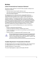
Notices Federal Communications Commission Statement This device complies with Part 15 of the FCC Rules. Operation is subject to the following two conditions: • • This device may not cause harmful interference, and This device must accept any interference received including interference that may cause undesired operation. This equipment has been tested and found to comply with the limits for a Class B digital device, pursuant to Part 15 of the FCC Rules.
Safety information Electrical safety • • • • • • To prevent electrical shock hazard, disconnect the power cable from the electrical outlet before relocating the system. When adding or removing devices to or from the system, ensure that the power cables for the devices are unplugged before the signal cables are connected. If possible, disconnect all power cables from the existing system before you add a device.
About this guide This user guide contains the information you need when installing and configuring the motherboard. How this guide is organized This user guide contains the following parts: • • • • • Chapter 1: Product introduction This chapter describes the features of the motherboard and the new technologies it supports. Chapter 2: Hardware information This chapter lists the hardware setup procedures that you have to perform when installing system components.
Conventions used in this guide To make sure that you perform certain tasks properly, take note of the following symbols used throughout this manual. DANGER/WARNING: Information to prevent injury to yourself when trying to complete a task. CAUTION: Information to prevent damage to the components when trying to complete a task. IMPORTANT: Instructions that you MUST follow to complete a task. NOTE: Tips and additional information to help you complete a task.
KFSN4-DRE Series specifications summary Model Name Processor / System Bus Core Logic Form Factor ASUS Features Smart Fan Rack Ready (Rack and Pedestal dual use) Rack Optimized (Dedicated for Rack) ASWM2.
KFSN4-DRE Series specifications summary Onboard I/O Connectors Rear I/O Connectors Management Solution Monitoring EMI Environment Floppy Connector PSU Connector Management Connector USB Connectors Fan Header SMBus Chassis Intruder Front LAN LED Serial Port Header External Serial Port External USB Port VGA Port RJ-45 PS/2 KB/Mouse Software Out of Band Remote Management CPU Temperature FAN RPM US (FCC, CFR47 Part 15, Class B) Europe (CE, EN55022 & EN55024) 1 1 24-pin ATX power connector + 8-pin ATX 12V
This chapter describes the motherboard features and the new technologies it supports.
Chapter summary 1 1.1 Welcome!....................................................................................... 1-1 1.3 Serial number label....................................................................... 1-1 1.2 1.4 Package contents.......................................................................... 1-1 Special features.............................................................................
1.1 Welcome! Thank you for buying an ASUS® KFSN4-DRE series motherboard! The motherboard delivers a host of new features and latest technologies, making it another standout in the long line of ASUS quality motherboards! Before you start installing the motherboard, and hardware devices on it, check the items in your package with the list below. 1.2 Package contents Check your motherboard package for the following items.
1.4 Special features 1.4.1 Product highlights Latest processor technology The motherboard comes with dual 1207-pin surface mount Land Grid Array (LGA) sockets coded Socket F, designed for AMD Opteron™ 2000 series processors. The motherboard with the new socket supports registered DDR2-667/533 memory, delivering advanced performance and ensuring reliable data protection.
Serial ATA 3Gb/s technology The motherboard supports the next-generation Serial ATA 3Gb/s technology through the Serial ATA interfaces and the NVIDIA® nForce4® PRO chipset. The SATA 3Gb/s specification provides twice the bandwidth of the current Serial ATA products. Additionally, Serial ATA allows thinner, more flexible cables with lower pin count, and reduced voltage requirement.
1-4 Chapter 1: Product introduction
This chapter lists the hardware setup procedures that you have to perform when installing system components. It includes description of the jumpers and connectors on the motherboard.
Chapter summary 2 2.1 Before you proceed...................................................................... 2-1 2.3 Central Processing Unit (CPU).................................................... 2-9 2.2 2.4 2.5 2.6 2.7 Motherboard overview.................................................................. 2-3 System memory.......................................................................... 2-13 Expansion slots...........................................................................
2.1 Before you proceed Take note of the following precautions before you install motherboard components or change any motherboard settings. • Unplug the power cord from the wall socket before touching any component. Use a grounded wrist strap or touch a safely grounded object or a metal object, such as the power supply case, before handling components to avoid damaging them due to static electricity. Hold components by the edges to avoid touching the ICs on them.
SAS LED (for KFSN4-DRE/SAS only) The green heartbeat LED blinks per second to indicate that the LSI 1064E chipset is working normally. ® 2. LED1 (green) KFSN4-DRE Series SAS LED 3. 4. Blinks Normal OFF Abnormal CPU warning LED (CPU_WARN1) The CPU warning LED lights up to indicate that a processor is not installed or the processor is not installed properly in CPU 1 socket. Memory warning LED (MEM_WARN1) The memory warning LED lights up to indicate that there is no power in the memory DIMMs.
2.2 Motherboard overview Before you install the motherboard, study the configuration of your chassis to ensure that the motherboard fits into it. To optimize the motherboard features, we highly recommend that you install it in an SSI CEB 1.1 compliant chassis. Make sure to unplug the chassis power cord before installing or removing the motherboard. Failure to do so can cause you physical injury and damage motherboard components! 2.2.
2.2.
KFSN4-DRE/2S model 33cm (13in) REAR_FAN4 T: Mouse B: Keyboard ATXPWR1 PSUSMB1 SATA4 SATA3 SATA2 SEC_IDE1 DDR2 DIMM_B2 (64/72 bit, 240-pin module) FAN_SEL1 COM1 REAR_FAN2 DDR2 DIMM_A2 (64/72 bit, 240-pin module) LAN1_EN1 REAR_FAN1 DDR2 DIMM_B1 (64/72 bit, 240-pin module) LAN2_EN1 DDR2 DIMM_A1 (64/72 bit, 240-pin module) nForce Professional 2200 ® BCM 5721 LAN1 LAN2 BCM 5721 BUZZ1 FRNT_FAN5 KFSN4-DRE_2S VGA1 DDR2 DIMM_A4 (64/72 bit, 240-pin module) DDR2 DIMM_A3 (64/72 bit, 240-pin m
KFSN4-DRE model 33cm (13in) REAR_FAN4 T: Mouse B: Keyboard ATXPWR1 PSUSMB1 SATA4 SATA3 SATA2 SEC_IDE1 DDR2 DIMM_B2 (64/72 bit, 240-pin module) FAN_SEL1 REAR_FAN2 COM1 DDR2 DIMM_A4 (64/72 bit, 240-pin module) DDR2 DIMM_A3 (64/72 bit, 240-pin module) REAR_FAN3 DDR2 DIMM_A2 (64/72 bit, 240-pin module) LAN1_EN1 REAR_FAN1 DDR2 DIMM_B1 (64/72 bit, 240-pin module) LAN2_EN1 DDR2 DIMM_A1 (64/72 bit, 240-pin module) nForce Professional 2200 ® BCM 5721 LAN1 LAN2 BCM 5721 BUZZ1 FRNT_FAN5 KFSN
2.2.5 Layout contents Slots/Soocket 1. CPU sockets 3. PCI Express x 16 slots 2. 4. Jumpers 1. 2-13 BMC socket 2-18 Clear RTC RAM (CLRTC1) Gigabit LAN1 controller setting (3-pin LAN1_EN1, LAN2_EN1) 4. Fan control setting (3-pin FAN_SEL1) 5. 6. 2-9 DDR2 sockets 2. 3.
Internal connectors Page 2. 2-24 1. Floppy disk drive connector (34-1 pin FLOPPY1) 3. Serial ATA connectors (7-pin SATA1, SATA2, SATA3, SATA4) 4. 5. 6. 7. 8. 9. 10. 11. 12. 13.
2.3 Central Processing Unit (CPU) The motherboard comes with dual surface mount Socket F designed for the AMD® Opteron® 2000 series CPU in the Land Grid Array (LGA) package. • Upon purchase of the motherboard, make sure that the PnP cap is on the socket and the socket contacts are not bent. Contact your retailer immediately if the PnP cap is missing, or if you see any damage to the PnP cap/socket contacts/motherboard components.
2. Press the load lever with your thumb (A), then move it to the left (B) until it is released from the retention tab. Retention tab Load lever A PnP cap This side of the socket box should face you. B To prevent damage to the socket pins, do not remove the PnP cap unless you are installing a CPU. 3. Lift the load lever in the direction of the arrow to a 135º angle. 4.
The CPU fits in only one correct orientation. DO NOT force the CPU into the socket to prevent bending the connectors on the socket and damaging the CPU! 6. Close the load plate (A), then push the load lever (B) until it snaps into the retention tab.
2.3.2 Installing the heatsink The AMD Opteron™ 2000 series processors require a specially designed heatsink to ensure optimum thermal condition and performance. Make sure that you use only qualified heatsink assembly. Follow these steps to install the CPU heatsink. 1. Place the heatsink on top of the installed CPU, making sure that the screw holes are matched with the heatsink standoffs. 2. Secure the heatsink with two screws.
2.4 System memory 2.4.1 Overview The motherboard comes with sixteen (16) Double Data Rate 2 (DDR2) Dual Inline Memory Modules (DIMM) sockets. A DDR2 module has the same physical dimensions as a DDR DIMM but has a 240-pin footprint compared to the 184-pin DDR DIMM. DDR2 DIMMs are notched differently to prevent installation on a DDR DIMM socket.
2.4.2 Memory Configurations You may install 256 MB, 512 MB, 1 GB, 2, or 4 GB registered ECC DDR2 DIMMs into the DIMM sockets using the memory configurations in this section. • For dual-channel configuration, the total size of memory module(s) installed per channel must be the same for better performance. Single CPU: DIMM_A1=DIMM_A2=DIMM_B1=DIMM_B2 Dual CPU: DIMM_A1=DIMM_A2=DIMM_B1=DIMM_B2= DIMM_C1=DIMM_C2 =DIMM_D1=DIMM_D2 • Always install DIMMs with the same CAS latency.
2.4.3 Installing a DIMM Unplug the power supply before adding or removing DIMMs or other system components. Failure to do so can cause severe damage to both the motherboard and the components. 2 To install a DIMM: 1. 2. 3. 3 Unlock a DIMM socket by pressing the retaining clips outward. Align a DIMM on the socket such that the notch on the DIMM matches the break on the socket. Firmly insert the DIMM into the socket until the retaining clips snap back in place and the DIMM is properly seated.
2.5 Expansion slots In the future, you may need to install expansion cards. The following sub‑sections describe the slots and the expansion cards that they support. Make sure to unplug the power cord before adding or removing expansion cards. Failure to do so may cause you physical injury and damage motherboard components. 2.5.1 Installing an expansion card To install an expansion card: 1. 2. 3. 4. 5. 6.
2.5.
2.5.4 PCI Express x16 slot (x8 link or x16 link) ® This motherboard supports PCI Express x16 cards that comply with the PCI Express specifications. The diagram shows the location of the PCI Express x16 slot. KFSN4-DRE Series PCI Express slot The number of PCIE slot differs by model. The KFSN4-DRE/SAS comes with one PCIE x 16 slot (x 8link); the KFSN4-DRE/2S comes with two PCIE x 16 slot (x 8link); the KFSN4-DRE comes with one PCIE x 16 slot (x 16link). 2.5.
2.6 1. Jumpers Clear RTC RAM (CLRTC1) This jumper allows you to clear the Real Time Clock (RTC) RAM in CMOS. You can clear the CMOS memory of date, time, and system setup parameters by erasing the CMOS RTC RAM data. The onboard button cell battery powers the RAM data in CMOS, which include system setup information such as system passwords. To erase the RTC RAM: 1. Turn OFF the computer and unplug the power cord. 2. Remove the onboard battery. 3. Move the jumper cap from pins 1-2 (default) to pins 2-3.
2. Gigabit LAN1 controller setting (3-pin LAN1_EN1, LAN2_EN1) These jumpers allow you to enable or disable the onboard Broadcom® BCM5721 Gigabit LAN1/2 controller. Set to pins 1-2 to activate the Gigabit LAN feature. LAN1_EN1 2 3 ® 1 2 Enable (Default) Disable LAN2_EN1 1 2 KFSN4-DRE Series LAN setting Disable VGA Graphics controller setting (3-pin VGA_EN1) This jumper allows you to enable or disable the onboard ATI ES1000 video graphics controller.
4. Fan control setting (3-pin FAN_SEL1) This jumper allows you to switch for fan pin selection. Set to pins 1-2 for 4-pin fans or pins 2-3 for 3-pin fans. FAN_SEL1 2 3 ® 1 2 4-PIN FAN (Default) 3-PIN FAN KFSN4-DRE Series Fan setting 5. • If you use a 4-pin fan but set the jumper to pin 2-3, the fan you installed may not work. • If you use a 3-pin fan but set the jumper for a 4-pin fan, the fan controll will not work and the fan you installed will always run at full speed.
6. Force BIOS recovery setting (3-pin RECOVERY1) This jumper allows you to quickly update or recover the BIOS settings when it becomes corrupted. To update the BIOS: Prepare a floppy disk that contains the latest BIOS for the motherboard and the AFUDOS utility. Make sure you download the correct BIOS for your motherboard model. 2. Set the jumper to pins 2-3. 3. Insert the floppy disk then turn on the system to update the BIOS. 4. Shut down the system. 5. Set the jumper back to pins 1-2. 6.
2.7 Connectors 2.7.1 Rear panel connectors 1. 2. 3. 4. 5. 6. 7. 8. 1 2 3 4 5 6 7 8 PS/2 mouse port (green). This port is for a PS/2 mouse. RJ-45 port for iKVM. This RJ-45 port functions only when you install ASMB3/iKVM management card. PS/2 keyboard port (purple). This port is for a PS/2 keyboard. USB 2.0 ports 1 and 2. These two 4-pin Universal Serial Bus (USB) ports are available for connecting USB 2.0 devices. Serial (COM1) port.
2.7.2 Floppy disk drive connector (34-1 pin FLOPPY1) This connector is for the provided floppy disk drive (FDD) signal cable. Insert one end of the cable to this connector, then connect the other end to the signal connector at the back of the floppy disk drive. ® 1. Internal connectors FLOPPY1 PIN 1 NOTE: Orient the red markings on the floppy ribbon cable to PIN 1. KFSN4-DRE Series Floppy disk drive connector 2.
PRI_IDE1 ® PIN 1 SEC_IDE1 PIN 1 NOTE: Orient the red markings (usually zigzag) on the IDE ribbon cable to PIN 1. KFSN4-DRE Series IDE connector 3. Serial ATA connectors (7-pin SATA1, SATA2, SATA3, SATA4) Supported by the NVIDIA® nForce4™ chipset, these connectors are for the Serial ATA signal cables for Serial ATA hard disk drives that allows up to 3Gb/s of data transfer rate. ® If you installed Serial ATA hard disk drives, you can create a RAID 0, RAID 1, RAID 1+0, RAID 5, or JBOD configuration.
Hard disk activity LED connector (4-pin HDLED1) This connector is for the storage add-on card cable connected to the SCSI or SATA add-on card. The read or write activities of any device connected to the SCSI or SATA add-on card causes the front panel LED to light up. ® 4. HDLED1 PIN1 NC ADD_IN_CARDADD_IN_CARDNC KFSN4-DRE Series storage card activity LED connector 5. USB connector (10-1 pin USB34) This connector is for USB 2.0 ports.
6. Front and rear fan connectors (3-pin FRNT_FAN1, FRNT_FAN2, FRNT_ FAN3, FRNT_FAN4, REAR_FAN1, REAR_FAN2, REAR_FAN3, REAR_ FAN4, REAR_FAN5, REAR_FAN6) The fan connectors support cooling fans of 350mA~2000mA (24 W max.) or a total of 1A~3.48A (41.76 W max.) at +12V. Connect the fan cables to the fan connectors on the motherboard, making sure that the black wire of each cable matches the ground pin of the connector. DO NOT forget to connect the fan cables to the fan connectors.
8. ATX power connectors (24-pin ATXPWR1, 8-pin ATX12V1) These connectors are for an ATX power supply plugs. The power supply plugs are designed to fit these connectors in only one orientation. Find the proper orientation and push down firmly until the connectors completely fit. • DO NOT forget to connect the 8-pin ATX +12 V power plug; otherwise, the system will not boot. • Use of a PSU with a higher power output is recommended when configuring a system with more power-consuming devices.
10. SAS connectors (KFSN4-DRE/SAS model only) SAS2 SAS3 GND RSATA_RXP2 RSATA_RXN2 GND RSATA_TXN2 RSATA_TXP2 GND GND RSATA_RXP3 RSATA_RXN3 GND RSATA_TXN3 RSATA_TXP3 GND SAS4 GND RSATA_RXP4 RSATA_RXN4 GND RSATA_TXN4 RSATA_TXP4 GND SAS1 GND RSATA_RXP1 RSATA_RXN1 GND RSATA_TXN1 RSATA_TXP1 GND ® This motherboard comes with four Serial Attached SCSI (SAS) connectors, the next-generation storage technology that supports both Series SCSI and Serial ATA (SATA). Each connector supports one device.
11. SAS LSI1064E ports LED connector (18-1 pin SASLED1) (KFSN4-DRE/SAS model only) ACT_LED6 ACT_LED7 ACT_LED0 ACT_LED1 ACT_LED2 ACT_LED3 ACT_LED4 ACT_LED5 ® This connector is for the front panel LED port indicator that shows the SAS HDD status. PIN1 KFSN4-DRE Series SASLED connector FLT_LED0 FLT_LED1 FLT_LED2 FLT_LED3 GND FLT_LED4 FLT_LED5 FLT_LED6 FLT_LED7 SASLED1 12.
13. Auxiliary panel connector (20-2 pin AUX_PANEL1) This connector supports several server system functions. +5VSB PIN1 KFSN4-DRE Series Auxiliary panel connector 1. 2. 3. 4. 5. 6. 7.
14. System panel connector (20-1 pin PANEL1) ® POWERLED+ NC POWERLEDMLED+ MLEDNC +5V GND GND SPKROUT This connector supports several chassis-mounted functions. KFSN4-DRE Series System panel connector NMIBTN# GND POWERBTN# GND NC RESETBTN# GND IDELED+ IDELED- PANEL1 The system panel connector is color-coded for easy connection. Refer to the connector description below for details. • • • • • 2-32 System power LED (Green 3-pin POWERLED) This 3-pin connector is for the system power LED.
This chapter describes the power up sequence, and ways of shutting down the system.
Chapter summary 3.1 3.2 3 Starting up for the first time......................................................... 3-1 Powering off the computer...........................................................
3.1 Starting up for the first time 1. After making all the connections, replace the system case cover. 2. Be sure that all switches are off. 3. Connect the power cord to the power connector at the back of the system chassis. 4. Connect the power cord to a power outlet that is equipped with a surge protector. 5. Turn on the devices in the following order: a. Monitor c. System power b. 6.
3.2 Powering off the computer 3.2.1 Using the OS shut down function If you are using Windows® 2000/2003 Server: 1. Click the Start button then click Shut Down. 2. Select Shut Down from the What do you want the computer to do? list box. 3. Select Shutdown Event Tracker. 4. Make sure that the Planned check box is checked. 5. Select shutdown option from the list box. 6. If necessary, key in comments. 7. Click OK. 3.2.
This chapter tells how to change the system settings through the BIOS Setup menus. Detailed descriptions of the BIOS parameters are also provided.
Chapter summary 4 4.1 Managing and updating your BIOS............................................. 4-1 4.3 Main menu..................................................................................... 4-8 4.2 4.4 4.5 4.6 4.7 4.8 BIOS setup program..................................................................... 4-5 Advanced menu.......................................................................... 4-13 Server menu...............................................................................
4.1 Managing and updating your BIOS The following utilities allow you to manage and update the motherboard Basic Input/Output System (BIOS) setup. 1. 2. ASUS AFUDOS (Updates the BIOS using a bootable floppy disk) ASUS CrashFree BIOS 2 (Updates the BIOS using a bootable floppy disk or the motherboard support CD when the BIOS file fails or gets corrupted.) Refer to the corresponding sections for details on these utilities.
4.1.2 AFUDOS utility The AFUDOS utility allows you to update the BIOS file in DOS environment using a bootable floppy disk with the updated BIOS file. This utility also allows you to copy the current BIOS file that you can use as backup when the BIOS fails or gets corrupted during the updating process. Copying the current BIOS To copy the current BIOS file using the AFUDOS utility: 1. 2. • Make sure that the floppy disk is not write-protected and has at least 1024KB free space to save the file.
Write the BIOS filename on a piece of paper. You need to type the exact BIOS filename at the DOS prompt. 2. 3. Copy the AFUDOS utility (afudos.exe) from the motherboard support CD to the bootable floppy disk you created earlier. Boot the system in DOS mode, then at the prompt type: afudos /i[filename] where [filename] is the latest or the original BIOS file on the bootable floppy disk. A:\>afudos /iKFSN4DRE.ROM 4. The utility verifies the file and starts updating the BIOS. A:\>afudos /iKFSN4DRE.
4.1.3 ASUS CrashFree BIOS 2 utility The ASUS CrashFree BIOS 2 is an auto recovery tool that allows you to restore the BIOS file when it fails or gets corrupted during the updating process. You can update a corrupted BIOS file using the motherboard support CD or the floppy disk that contains the updated BIOS file. • Prepare the motherboard support CD or the floppy disk containing the updated motherboard BIOS before using this utility.
4.2 BIOS setup program This motherboard supports a programmable Serial Peripheral Interface (SPI) chip that you can update using the provided utility described in section 4.1 Managing and updating your BIOS. Use the BIOS Setup program when you are installing a motherboard, reconfiguring your system, or prompted to “Run Setup.” This section explains how to configure your system using this utility.
4.2.1 BIOS menu screen Menu items Main Menu bar Advanced Server Configuration fields General help BIOS SETUP UTILITY Security Boot Exit System Date System Time Floppy A [Wed, 07/25/2007] [11:07:30] [1.
4.2.4 Menu items The highlighted item on the menu bar displays the specific items for that menu. For example, selecting Main shows the Main menu items. System Date System Time [Wed 07/25/2007] [11:17:09] Use [ENTER] to select Floppy A [1.44 MB 3½”] Use [+] or [-] to The other items (Advanced, Power, Boot, and Exit) on the menu bar have their respective menu items. 4.2.
4.3 Main menu When you enter the BIOS Setup program, the Main menu screen appears, giving you an overview of the basic system information. Refer to section 4.2.1 BIOS menu screen for information on the menu screen items and how to navigate through them. Main Advanced Server BIOS SETUP UTILITY Security Boot Exit System Date System Time [Wed, 07/25/2007] [11:07:30] Use [ENTER] to select a field. Floppy A [1.44 MB 3½”] Use [+] or [-] to configure system Date.
4.3.4 IDE Configuration The items in this menu allow you to set or change the configurations for the IDE devices installed in the system. Select an item then press if you wish to configure the item. BIOS SETUP UTILITY Main IDE Configuration OnBoard IDE Controller IDE DMA Transfer nVidia RAID Setup [Both] [Enabled] DISABLED: disables the integrated IDE Controller. PRIMARY: enables only the Primary IDE Controller. SECONDARY: enables only the Secondary IDE Controller.
4.3.5 Primary/Secondary IDE Master/Slave; Tertiary/Fourth/ Fifth/Sixth IDE Master The BIOS automatically detects the connected IDE devices. There is a separate sub-menu for each IDE device. Select a device item, then press to display the IDE device information. BIOS SETUP UTILITY Main Disabled: Disables LBA Mode. Auto: Enables LBA Mode if the device supports it and the device is not already formatted with LBA Mode disabled. Primary IDE Master Device :Hard Disk Vendor :xxxxxxxxx Size :xx.
PIO Mode [Auto] Allows you to select the data transfer mode. Configuration options: [Auto] [0] [1] [2] [3] [4] DMA Mode [Auto] Sets the DMA mode. Configuration options: [Auto] [SWDMA0] [SWDMA1] [SWDMA2] [MWDMA0] [MWDMA1] [MWDMA2] [UDMA0] [UDMA1] [UDMA2] [UDMA3] [UDMA4] S.M.A.R.T. [Auto] Sets the Smart Monitoring, Analysis, and Reporting Technology. Configuration options: [Auto] [Disabled] [Enabled] 32Bit Data Transfer [Disabled] Enables or disables 32-bit data transfer.
Processor Displays the installed processor information. BIOS SETUP UTILITY Main Processor Information *** CPU1 : Brand D Dual-Core AMD Opteron(tm) Processor 2212 CPU Core Number : 2 ID/uCode 040F12h/None Speed 2.20GHz Ratio Actual 11 Max 11 Cache L1/128KB L2/1024KB Revision F2 →← ↑↓ +Tab F1 F10 ESC Select Screen Select Item Change Field Select Field General Help Save and Exit Exit V02.61 (C)Copyright 1985-2006, American Megatrends, Inc. System Memory Displays the installed system memory information.
4.4 Advanced menu The Advanced menu items allow you to change the settings for the CPU and other system devices. Take caution when changing the settings of the Advanced menu items. Incorrect field values can cause the system to malfunction. Main Advanced Server BIOS SETUP UTILITY Security Boot Exit WARNING: Setting wrong values in the below sections may cause system to malfunction.
MTRR Mapping [Continuous] Determines the method used for programming processor MTRRs when using more than 4GB of system memory. Configuration options: [Continuous] [Discrete] PowerNow [Enabled] Enables or disables the generation of ACPI_PPC/_PSS/_PCT objects. Configuration options: [Enabled] [Disabled] Secure Virtual Machine Mode [Enabled] Enables or disables Secure Virtual Machine mode. 4.4.2 Chipset Configuration The Chipset configuration menu allows you to change advanced chipset settings.
Memory Configuration The memory configuration menu allows you to change the memory settings. Advanced BIOS SETUP UTILITY Memory Configuration Bank Interleaving Channel Interleaving Node Interleaving Memory Hole Remapping Unganged Mode support Enable Bank Memory Interleaving [Auto] [Auto] [Disabled] [Enabled] [Enabled] →← ↑↓ +Tab F1 F10 ESC Select Screen Select Item Change Field Select Field General Help Save and Exit Exit V02.61 (C)Copyright 1985-2006, American Megatrends, Inc.
DRAM Timing Configuration Main Advanced BIOS SETUP UTILITY DRAM Timing Configuration Memory Clock Mode DRAM Timing Mode Options [Auto] [Auto] Auto Limit Manual Memory Clock Mode [Auto] Configuration options: [Auto] [Limit] [Manual] The following item appears when Memory Clock Mode is set to [Limit] or [Manual]. Memclock Value [200 MHz] Configuration options: [200 MHz] [266 MHz] [333 MHz] [400 MHz] [533 MHz] DRAM Timing Mode [Auto] Allows you to select the DRAM timing mode.
The following items appear when DRAM Timing Mode is set to [DCT 0], or [Both]. tRWTTO [2 CLK] Configuration options: [2 CLK] [3 CLK] [4 CLK] [5 CLK] [6 CLK] [7 CLK] [8 CLK] [9 CLK] [Auto] tWRRD [0 CLK] Configuration options: [0 CLK] [1 CLK] [2 CLK] [3 CLK] [Auto] The following item appears when DRAM Timing Mode is set to [DCT 0], [DCT 1] or [Both]. tWTR [Auto] Configuration options: [Auto] [1 CLK] [2 CLK] [3 CLK] The following items appear when DRAM Timing Mode is set to [DCT 0], or [Both].
ECC Configuration Main Advanced ECC Configuration BIOS SETUP UTILITY [Enabled] Set GART size in systems without AGP, or disable altogether. Some OSes require valid GART for proper operation. If AGP is present, select appropriate option to ensure proper AGP operation. ECC Configuration [Enabled] Allows you to enable or disable ECC configuration.
SouthBridge/CK804 Configuration The SouthBridge/CK804 Configuration menu allows you to change the Southbridge settings. Advanced BIOS SETUP UTILITY SouthBridge/CK804 Configuration CPU Spread Spectrum [Disabled] →← ↑↓ +Tab F1 F10 ESC Select Screen Select Item Change Field Select Field General Help Save and Exit Exit V02.61 (C)Copyright 1985-2006, American Megatrends, Inc. CPU Spread Spectrum [Disabled] Sets or disables the processor clock spread spectrum.
4.4.3 PCI PnP The PCI PnP menu items allow you to change the advanced settings for PCI/PnP devices. The menu includes setting IRQ and DMA channel resources for either PCI/PnP or legacy ISA devices, and setting the memory size block for legacy ISA devices. Take caution when changing the settings of the PCI PnP menu items. Incorrect field values can cause the system to malfunction. Advanced BIOS SETUP UTILITY PCI/PnP Configuration Clear NVRAM during System Boot.
4.4.4 USB Configuration The items in this menu allows you to change the USB-related features. Select an item then press to display the configuration options. Advanced BIOS SETUP UTILITY USB Configuration Options Enabled Disabled USB Devices Enabled: None USB 1.1 Controller USB 2.0 Controller Legacy USB Support USB 2.
4.4.5 Peripheral Devices Configuration Advanced BIOS SETUP UTILITY Peripheral Devices Configuration OnBoard Floppy Controller Serial Port1 Address Serial Port2 Address Serial Port2 Address Parallel Port Address Parallel Port Mode Parallel Port IRQ [Enabled] [3F8/IRQ4] [2F8/IRQ3] [Normal] [378] [Normal] [IRQ7] Allows BIOS to Enable or Disable Floppy Controller. →← ↑↓ +Tab F1 F10 ESC Select Screen Select Item Change Field Select Field General Help Save and Exit Exit V02.
The following item appears when you set Parallel Port Mode to [ECP] or [ECP & EPP] ECP Mode DMA Channel [DMA3] This item allows you to set the Parallel Port ECP DMA. Configuration options: [DMA0] [DMA1] [DMA3] The following item appears when you set Parallel Port Mode to [ECP & EPP]. EPP Version [1.9] Allows selection of the Parallel Port EPP version. Configuration options: [1.9] [1.7] Parallel Port IRQ [IRQ7] Allows you to select the Parallel Port IRQ. Configuration options: [IRQ5] [IRQ7] 4.4.
4.4.7 APM Configuration This sub-menu allows you to change Advanced Power Management (APM) features. Select an item then press to display the configuration options. Advanced BIOS SETUP UTILITY APM Configuration Restore On AC Power Loss Resume by Ring Resume by PCIE Wake# Resume by RTC Options [Last State] [Disabled] [Disabled] [Disabled] Power Off Power On Last State →← ↑↓ +Tab F1 F10 ESC Select Screen Select Item Change Field Select Field General Help Save and Exit Exit V02.
4.4.
The following items appear when you enable the Smart Fan Control feature. CPU1/CPU2 Target Temperature [60] Allows you to set the CPU target temperature. Configuration options: [40] [45] [50] [55] [60] [65] [70] [75] [80] [85] System1 Target Temperature [50] Allows you to set the system target temperature.
4.5 Main Server menu Advanced Server BIOS SETUP UTILITY Security Boot Exit Configure Remote Access. Remote Access Configuration →← ↑↓ +Tab F1 F10 ESC Select Screen Select Item Change Field Select Field General Help Save and Exit Exit V02.61 (C)Copyright 1985-2006, American Megatrends, Inc. 4.5.1 Remote Access Configuration The items in this menu allows you to configure the Remote Access features. Select an item then press to display the configuration options.
Serial port number [COM1] Selects the serial port for console redirection. Configuration options: [COM1] [COM2] Baudrate [57600] Sets the baudrate. Configuration options: [115200] [57600] [38400] [19200] [9600] Flow Control [None] Allows you to select the flow control for console redirection. Configuration options: [None] [Hardware] [Software] Redirection After BIOS POST [Always] Sets the redirection mode after the BIOS Power-On Self-Test (POST). Some operating system may not work when set to Always.
4.6 Security The Security menu items allow you to change the system security settings. Select an item then press to display the configuration options. Main Advanced Server BIOS SETUP UTILITY Security Boot Exit to change password. again to disable password.
Main Advanced Server BIOS SETUP UTILITY Security Boot Exit to change password. again to disable password. Supervisor Password : Not Installed User Password : Not Installed Change Supervisor Password User Access Level Change User Password Password Check Chassis Intrusion Function [Full Access] [Setup] [Enabled] User Access Level [Full Access] This item allows you to select the access restriction to the Setup items.
4.7 Boot menu The Boot menu items allow you to change the system boot options. Select an item then press to display the sub-menu. Main Advanced Server BIOS SETUP UTILITY Security Boot Exit Specifies the Boot Device Priority sequence. Boot Device Priority Boot Settings Configuration →← ↑↓ +Tab F1 F10 ESC Select Screen Select Item Change Field Select Field General Help Save and Exit Exit V02.61 (C)Copyright 1985-2006, American Megatrends, Inc. 4.7.
4.7.2 Boot Settings Configuration BIOS SETUP UTILITY Boot Boot Settings Configuration Quick Boot Full Logo Display Bootup Num-Lock PS/2 Mouse Support POST Error Setup Prompt Interrupt 19 Capture [Enabled] [Enabled] [On] [Auto] [Enabled] [Enabled] [Disabled] Allows BIOS to skip certain tests while booting. This will decrease the time needed to boot the system. →← ↑↓ +Tab F1 F10 ESC Select Screen Select Item Change Field Select Field General Help Save and Exit Exit V02.
4.8 Exit menu The Exit menu items allow you to load the optimal or failsafe default values for the BIOS items, and save or discard your changes to the BIOS items. Main Advanced Server BIOS SETUP UTILITY Security Boot Exit Save Changes and Exit Discard Changes and Exit Discard Changes Exit system setup after saving the changes. Load Setup Defaults F10 key can be used for this operation. →← ↑↓ +Tab F1 F10 ESC Select Screen Select Item Change Field Select Field General Help Save and Exit Exit V02.
4-34 Chapter 4: BIOS setup
This chapter provides instructions for setting up, creating, and configuring RAID sets using the available utilities.
Chapter summary 5 5.1 Setting up RAID............................................................................. 5-1 5.3 LSI Logic MPT Setup Utility (KFSN4-DRE/SAS model only)..... 5-9 5.2 NVIDIA® RAID configurations.......................................................
5.1 Setting up RAID The motherboard comes with the following RAID solutions: KFSN4-DRE; KFSN4-DRE/2S model • The NVIDIA® nForce Professional 2200 chipset comes with a built-in SATA RAID controller that allows you to configure RAID 0 and RAID 1 with SATA hard disk drives. KFSN4-DRE/SAS model • • The NVIDIA® nForce Professional 2200 chipset comes with a built-in SATA RAID controller that allows you to configure RAID 0 and RAID 1 with SATA hard disk drives.
5.1.2 Installing hard disk drives The motherboard supports Serial ATA for RAID set configuration. For optimal performance, install identical drives of the same model and capacity when creating a disk array. To install the SATA hard disks for RAID configuration: 1. 2. 3. Install the SATA hard disks into the drive bays following the instructions in the system user guide. Connect a SATA signal cable to the signal connector at the back of each drive and to the SATA connector on the motherboard.
5.2 NVIDIA® RAID configurations The motherboard includes a high performance SATA RAID controller integrated in the NVIDIA® nForce Professional 2200 chip. The RAID controller supports RAID 0 and RAID 1 using the four independent Serial ATA channels. 5.2.1 Entering the NVIDIA® RAID Utility To enter the NVIDIA® RAID Utility: 1. 2. Restart the computer. During POST, press to display the utility main menu.
5.2.2 Creating a RAID Volume To create a RAID 0 set: 1. 2. From the Define a New Array menu, select RAID Mode, then press . A pop-up menu appears.Use the up or down arrow keys to select a RAID mode , then press . You can select either Mirroring, Striping, Spanning, Stripe Mirroring, or RAID 5. Mirroring Striping Stripe Mirroring Spanning RAID 5 • The RAID mode is set to Mirroring by default. • Not all RAID modes are supported on all platforms.
NVIDIA RAID Utility Mar 23 2006 - Define a New Array RAID Mode: Striping Striping Block: Optimal Free Disks Loc Disk Model Name Array Disks Loc Disk Model Name [→] Add 1.0.M XXXXXXXXXXXXXXXXXX 1.1.M XXXXXXXXXXXXXXXXXX [←] Del [ESC] QUIT [F6] Back [F7] Finish [TAB] Navigate [↑↓] Select [ENTER] Popup 4. 5. Press to create the RAID set. A pop-up window appears.
5.2.3 Rebuilding a RAID set To rebuild a RAID set: 1. From the Array List, use the up or down arrow keys to select the RAID set you want to rebuild, then press . The RAID set details appear. NVIDIA RAID Utility Mar 23 2006 - Array List Boot Id Status Vendor Array Yes Yes 2 2 Healthy Healthy NVIDIA NVIDIA STRIPING MIRRORING [Ctrl-X]Exit 2. 3. [↑↓]Select [B]Set Boot Model Name [N]New Array XXX.XXG XXX.XXG [ENTER]Detail Press .
5.2.4 Deleting a RAID array To delete a RAID array: 1. From the Array List, use the up or down arrow keys to select the RAID set you want to delete, then press . The RAID set details appear. NVIDIA RAID Utility Mar 23 2006 - Array List Boot Id Status Vendor Array No No 4 3 Healthy Healthy NVIDIA NVIDIA STRIPING MIRRORING [R] Rebuild 2. 3. [D] Delete [C] Clear Disk Model Name XXX.XXG XXX.XXG [ENTER] Return When the array details appear, press to delete the RAID set.
5.2.5 Clearing the disk data You will lose all data when you clear a disk! To clear the disk data: 1. From the Array List, use the up or down arrow keys to select a RAID set, then press . The RAID set details appear. NVIDIA RAID Utility Mar 23 2006 - Array List Boot Id Status Vendor Array No No 4 3 Healthy Healthy NVIDIA NVIDIA STRIPING MIRRORING [Ctrl-X]Exit 2. [↑↓]Select [B]Set Boot Model Name XXX.XXG XXX.
5.3 LSI Logic MPT Setup Utility (KFSN4-DRE/SAS model only) The LSI Logic MPT Setup Utility is an integrated RAID solution that allows you to allows you to create the following RAID set(s) from SAS hard disk drives supported by the LSI1064E PCI-E SAS controller: • RAID 1 (Integrated Mirroring) • RAID 0 (Integrated Striping) • RAID 1E (Integrated Mirroring Enhanced) 5.3.1 Integrated Mirroring Overview The Integrated Mirroring (IM) feature supports simultaneous mirrored volumes with two disks (IM).
3. The following screen appears. Select a channel and press to enter the setup. LSI Logic Config Utility v6.16.00.00 (2007.05.07) Adapter List Global Properties Adapter PCI PCI PCI PCI FW Revision Status BUS Dev Fnc Slot SAS1064E 04 03 00 00 1.22.01.00-IR Enabled Esc = Exit Menu F1/Shift+1 = Help Alt+N = Global Properties -/+ = Alter Boot Order Boot Order 0 Ins/Del = Alter Boot List The numbers of the channel depend on the controller. 4. The Adapter Properties screen appears.
6. The Create New Array screen shows the disks you can add to make up the IM volume. Use the arrow key to select a disk, then move the cursor to the RAID Disk column. To include this disk in the array, press <+>, <->, or . You may also specify the Hot Spare disk here. Select the disk, then move the cursor to the Hot Spr column, then press <+>, <->, or . LSI Logic Config Utility Create New Array -- SAS1064E Array Type: Array Size(MB): Slot Num 0 1 2 3 v6.16.00.00 (2007.05.
7. A confirmation screen appears. Press to keep existing data on the first disk. If you choose this option, data on the first disk will be mirrored on the second disk that you will add to the volume later. Make sure the data you want to mirror is on the first disk. Press to overwrite any data and create the new IM array. LSI Logic Config Utility v6.16.00.00 (2007.05.07) Create New Array Type -- SAS1064E M - Keep existing data, migrate to an IM array. Synchronization of disk will occur.
5.3.2 Integrated Mirroring Enhanced To create an IME volume: 1. The Adapter Properties screen appears. Use the arrow keys to select RAID Properties, then press . LSI Logic Config Utility Adapter Properties -- SAS1064E Adapter PCI Slot PCI Address(Bus/Dev/Func) MPT Firmware Revision SAS Address NVDATA Version Status Boot Order Boot Support v6.16.00.00 (2007.05.07) SAS1064E 00 04:00:00 1.22.01.00-IR 500E0101:23456712 2B.
3. The Create New Array screen shows the disks you can add to make up the IME volume. Integrated Mirroring Enhanced (IME) supports three to ten disks, or seven mirrored disks plus two hot spare disks. Use the arrow key to select a disk, then move the cursor to the RAID Disk column. To include this disk in the array, press <+>, <->, or . You may also specify the Hot Spare disk here. Select the disk, then move the cursor to the Hot Spr column, then press <+>, <->, or .
5.3.3 Integrated Striping (IS) volume Overview The Integrated Striping (IS) feature provides RAID 0 functionality, supporting volumes with two to eight disks. You may combine an IS volume with an IM or IME volume. Creating Integrated Striping volumes DO NOT combine Serial ATA and SAS disk drives in one volume. To create an IS volume: 1. 2. Turn on the system after installing all SAS hard disk drives. During POST, press to enter the SAS configuration utility. LSI Logic Corp.
4. The Select New Array Type screen appears. Use the arrow keys to select Create IS Volume, then press . LSI Logic Config Utility Select New Array Type -- SAS1064E v6.16.00.00 (2007.05.07) Create IM Volume Create Integrated Mirror Array of 2 disks plus up to 2 optional hot spares. Data on the primary disk may be migrated. Create IME Volume Create Integrated Mirrored Enhanced Array of 3 to 10 disks including up to 2 optional hot spares.
6. 7. Repeat step 5 to add the other disks to the volume. When done, press to create the array, then select Save changes then exit this menu. Create and save new array? Cancel Exit Save changes then exit this menu Discard changes then exit this menu Exit the Configuration Utility and Reboot 9. The utility creates the array. LSI Logic Config Utility v6.16.00.00 (2007.05.07) Processing...
5.3.4 Managing Arrays The LSI Logic MPT Setup Utility allows you to perform other tasks related to configuring and maintaining IM and IME volumes. Refer to this section to view volume properties, manage the hot spare disk, synchronize the array, activate the array, and delete the array. Viewing volume properties To view volume properties: 1. On the main menu, select RAID Properties.
3. The View Existing Array screen appears. Here you can view properties of the RAID array(s) created. If you have configured a hot spare, it will also be listed. if you created more than one array, you may view the next array by pressing . LSI Logic Config Utility View Array -- SAS1064E Array Identifier Type Scan Order Size(MB) Status v6.16.00.00 (2007.05.
Managing hot spares You may configure one disk as a global hot spare to protect critical data on the IM/ IME volume(s). You may create the hot spare disk at the same time you create the IM/IME volume. Refer to this section when adding a hot spare disk on an existing volume. If a disk on an IM/IME volume fails, the utility automatically rebuilds the failed disk data on the hot spare. When the failed disk is replaced, the utility assigns the replacement as the new hot spare. To create a hot spare: 1. 2.
4. Use the arrow key to select the disk you would like to configure as hot spare, then move the cursor to the Hot Spr column. Press <+>, <->, or . The Drive Status column field now shows Hot Spare. Press to commit the changes. LSI Logic Config Utility Manage Hot Spare -- SAS1064E Identifier Type Scan Order Size(MB) Status Slot Num 0 1 2 3 v6.16.00.00 (2007.05.
Activating an array If an array is removed from one controller/computer or moved to another, the array is considered inactive. When you add the array back to the system, you may reactivate the array. To activate the array: 1. From the Manage Array screen, select Activate Array, then press . LSI Logic Config Utility Manage Array -- SAS1064E Identifier Type Scan Order Size(MB) Status v6.16.00.00 (2007.05.
5.3.5 �������������������� Viewing SAS topology 1. From the Adapter Properties screen, select SAS Topology. LSI Logic Config Utility Adapter Properties -- SAS1064E Adapter PCI Slot PCI Address(Bus/Dev/Func) MPT Firmware Revision SAS Address NVDATA Version Status Boot Order Boot Support v6.16.00.00 (2007.05.07) SAS1064E 00 04:00:00 1.22.01.00-IR 500E0101:23456712 2B.
Selecting a boot disk You can select a boot disk in the SAS Topology screen. This disk is then moved to scan ID 0 on the next boot, and remains at this position. This makes it easier to set BIOS boot device options and to keep the boot device constant during device additions and removals. There can be only one boot disk. Follow these steps to select a boot disk: 1. 2. 3. 4. 5. In the LSI Logic Config Utility, select an adapter from the Adapter List. Select the SAS Topology option.
5.5.6 Global Properties From the Setup Utility screen, press to enter LSI Logic Configuration, then select Global Properties. The Global Properties menu allows you to change related settings. LSI Logic Config Utility v6.16.00.00 (2007.05.07) Adapter List Global Properties Adapter PCI PCI PCI PCI FW Revision Status BUS Dev Fnc Slot SAS1064E 04 03 00 00 1.22.01.
Boot Information Display Mode Sets the disk information display mode. Configuration options: [Display adapters & installed devices] [Display adapters only] [Display adapters and all devices] [Display minimal information] LSI Logic Config Utility Adapter List Global Properties Pause When Boot Alert Displayed Boot Information Display Mode Support Interrupt v6.16.00.00 (2007.05.
Restore Defaults This option allows you to discard the selections you made and restore the system defaults. LSI Logic Config Utility Adapter List Global Properties Pause When Boot Alert Displayed Boot Information Display Mode Support Interrupt v6.16.00.00 (2007.05.
5-28 Chapter 5: RAID configuration
This chapter provides instructions for installing the necessary drivers for different system components.
Chapter summary 6 6.1 RAID driver installation................................................................ 6-1 6.4 nVIDIA® driver installation.......................................................... 6-10 6.2 6.5 LAN driver installation.................................................................. 6-7 Management application and utilities installation...................
6.1 RAID driver installation After creating the RAID sets for your server system, you are now ready to install an operating system to the independent hard disk drive or bootable array. This part provides instructions on how to install the RAID controller drivers during OS installation. 6.1.1 Creating a RAID driver disk You may have to use another system to create the RAID driver disk from the system/motherboard support CD or from the Internet.
nVIDIA nForce SATA RAID Driver nVIDIA Windows Windows Windows Back Exit nForce SATA RAID Driver 2000 Server Server 2003 32 bit Server 2003 64 bit LSI 1064E SAS Driver nVIDIA nForce SATA RAID Driver Windows 2000 Server Windows Server 2003 32 bit Windows Server 2003 64 bit RHEL AS3 UP8 32 bit RHEL AS3 UP8 64 bit RHEL AS4 UP4 32 bit RHEL AS4 UP4 64 bit RHEL 5 32 bit RHEL 5 64 bit SLES 9.0 SP3 32 bit SLES 9.0 SP3 64 bit SLES 10 32 bit SLES 10 64 bit Back Exit 7. 8. 9.
To create a RAID driver disk in Windows®: 1. 2. Place the motherboard support CD in the optical drive. When the Drivers menu appears, click nVIDIA nForce(TM) SATA RAID Driver to create an nVIDIA nForce SATA RAID driver disk. To install the RAID driver: 1. 2. 3. Install an operating system to the selected hard disk drive. During installation, the computer prompts you to press the if you are installing a third-party SCSI or RAID driver.
6.1.2 Installing the RAID controller driver Windows® 2000/2003 Server OS To install the RAID controller driver when installing Windows® 2000/2003 Server OS: 1. Boot the computer using the Windows® 2000/2003 Server installation CD. The Windows® 2000/2003 Setup starts. 2. Press when the message “Press F6 if you need to install a third party SCSI or RAID driver...” appears at the bottom of the screen. 3. 6-4 When prompted, press to specify an additional device.
4. Insert the RAID driver disk you created earlier to the floppy disk drive, then press . 5. Select the NVIDIA RAID CLASS DRIVER (required), then press . 6. Press again at the Specigy Devices screen, then press .
7. Select NVIDIA RAID CLASS DRIVER (required), then press . The following windows appears listing both drrvers. 8. Press to continuen with Windows® 2000/2003 installation. DO NOT remove the floppy disk until the blue screen portion of Windows® 2000/2003 installation is completed.
6.2 LAN driver installation This section provides instructions on how to install the Broadcom® Gigabit LAN controller drivers on a Windows® 2000/2003 OS. To install the LAN controller drivers: 1. 2. 3. Restart the computer, then log on with Administrator privileges. Insert the motherboard/system support CD to the optical drive. The CD automatically displays the Drivers menu if Autorun is enabled in your computer.
6-8 4. Click Next when the InstallShield Wizard window appears. 5. Toggle I accept the terms in the license agreement and click Next to continue.
6. Click Install to start the installation. 7. Click Finish to exit the wizard when the installation is completed.
6.3 nVIDIA® driver installation This section provides the instructions on how to install the nVIDIA® Windows nFroce drivers, including NVIDIA SMBus Driver, NVIDIA Ethernet Driver, NVIDIA MediaShield, and NVIDIA Audio Driver. 6.3.1 Windows 2000/Server 2003 To install the nVIDIA® drivers on a Windows® 2000/ Server 2003 OS: 1. 2. Restart the computer, and then log on with Administrator privileges. Insert the motherboard/system support CD to the optical drive.
4. Click Next when the InstallShield Wizard window appears. 5. Check the box before the driver you want to install and click Next to continue.
6-12 6. Click Next to start the installation. 7. Click Finish to exit the wizard when the installation is completed.
6.4 Management applications and utilities installation The support CD that came with the motherboard package contains the drivers, management applications, and utilities that you can install to avail all motherboard features. The contents of the support CD are subject to change at any time without notice. Visit the ASUS website (www.asus.com) for updates. 6.4.1 Running the support CD Place the support CD to the optical drive.
6.4.3 Management Software menu The Management Software menu displays the available network and server monitoring applications. Click an item to install. 6.4.4 Utilities menu The Utilities menu displays the software applications and utilities that the motherboard supports. Click an item to install. 6.4.5 Contact information Click the Contact tab to display the ASUS contact information. You can also find this information on the inside front cover of this user guide.
This appendix includes additional information that you may refer to when configuring the motherboard.
Appendix summary A A.1 KFSN4-DRE/SAS model block diagram......................................A-1 A.3 KFSN4-DRE model block diagram...............................................A-3 A.2 KFSN4-DRE/2S model block diagram.........................................
KFSN4-DRE/SAS model block diagram 2 channel DDR2 SDRAM 8 x DIMMs AMD Opteron™/ Barcelona(L1SP) CPU2 Dual-Link x16 2.0GT/s 533/667MHz 64/128 bit 533/667MHz 64/128 bit x16 2.0GT/s AMD Opteron™/ Barcelona(L1SP) CPU1 2 channel DDR2 SDRAM 8 x DIMMs A.1 x16 2.0GT/s PCIE1 X8 2 IDE Ports (Ultra ATA 66/100/133) LSI 1064E x8 BCM5721 Gigabit LAN PCI-Express x1 BCM5721 Gigabit LAN PCI-Express x1 nVIDIA nForce Professional 2200 4 Serial ATA Ports Raid 0,1,10,5 USB2.
KFSN4-DRE/2S model block diagram 2 channel DDR2 SDRAM 8 x DIMMs AMD Opteron™/ Barcelona(L1SP) CPU2 Dual-Link x16 2.0GT/s 533/667MHz 64/128 bit 533/667MHz 64/128 bit x16 2.0GT/s AMD Opteron™/ Barcelona(L1SP) CPU1 2 channel DDR2 SDRAM 8 x DIMMs A.2 x16 2.0GT/s PCIE1 X8 PCIE2 X8 x8 2 IDE Ports (Ultra ATA 66/100/133) x8 nVIDIA nForce Professional 2200 BCM5721 Gigabit LAN PCI-Express x1 BCM5721 Gigabit LAN PCI-Express x1 4 Serial ATA Ports Raid 0,1,10,5 USB2.
KFSN4-DRE model block diagram 2 channel DDR2 SDRAM 8 x DIMMs AMD Opteron™/ Barcelona(L1SP) CPU2 Dual-Link x16 2.0GT/s 533/667MHz 64/128 bit 533/667MHz 64/128 bit x16 2.0GT/s AMD Opteron™/ Barcelona(L1SP) CPU1 2 channel DDR2 SDRAM 8 x DIMMs A.3 x16 2.0GT/s PCIE1 X16 x16 2 IDE Ports (Ultra ATA 66/100/133) nVIDIA nForce Professional 2200 BCM5721 Gigabit LAN PCI-Express x1 BCM5721 Gigabit LAN PCI-Express x1 4 Serial ATA Ports Raid 0,1,10,5 USB2.
A-4 Appendix A: Reference information