Motherboard M2N-E SLI
E2830 First Edition October 2006 Copyright © 2006 ASUSTeK COMPUTER INC. All Rights Reserved. No part of this manual, including the products and software described in it, may be reproduced, transmitted, transcribed, stored in a retrieval system, or translated into any language in any form or by any means, except documentation kept by the purchaser for backup purposes, without the express written permission of ASUSTeK COMPUTER INC. (“ASUS”).
Contents Notices.................................................................................................vii Safety information..............................................................................viii About this guide................................................................................... ix Typography........................................................................................... x M2N-E SLI specifications summary.......................................................
Contents 2.6 Jumpers............................................................................... 2-19 2.7 Connectors.......................................................................... 2-22 2.7.1 Rear panel connectors........................................... 2-22 2.7.2 Internal connectors................................................ 2-24 Chapter 3: Powering up 3.1 Starting up for the first time................................................. 3-1 3.2 Powering off the computer........
Contents 4.3.8 4.4 4.5 4.6 4.7 Installed Memory.................................................... 4-19 Advanced menu................................................................... 4-20 4.4.1 JumperFree Configuration...................................... 4-20 4.4.3 CPU Configuration.................................................. 4-23 4.4.4 PCIPnP.................................................................... 4-25 4.4.5 Onboard Device Configuration...............................
Contents 5.4 5.5 RAID configurations............................................................. 5-16 5.4.1 Installing hard disks................................................ 5-17 5.4.2 NVIDIA® RAID configurations.................................. 5-18 Creating a RAID driver disk.................................................. 5-25 Chapter 6: NVIDIA® SLI™ technology support 6.1 Overview................................................................................ 6-1 Requirements............
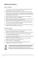
Notices Federal Communications Commission Statement This device complies with Part 15 of the FCC Rules. Operation is subject to the following two conditions: • This device may not cause harmful interference, and • This device must accept any interference received including interference that may cause undesired operation. This equipment has been tested and found to comply with the limits for a Class B digital device, pursuant to Part 15 of the FCC Rules.
Safety information Electrical safety • To prevent electrical shock hazard, disconnect the power cable from the electrical outlet before relocating the system. • When adding or removing devices to or from the system, ensure that the power cables for the devices are unplugged before the signal cables are connected. If possible, disconnect all power cables from the existing system before you add a device.
About this guide This user guide contains the information you need when installing and configuring the motherboard. How this guide is organized This manual contains the following parts: • Chapter 1: Product introduction This chapter describes the features of the motherboard and the new technology it supports. • Chapter 2: Hardware information This chapter lists the hardware setup procedures that you have to perform when installing system components.
Where to find more information Refer to the following sources for additional information and for product and software updates. 1. ASUS websites The ASUS website provides updated information on ASUS hardware and software products. Refer to the ASUS contact information. 2. Optional documentation Your product package may include optional documentation, such as warranty flyers, that may have been added by your dealer. These documents are not part of the standard package.
M2N-E SLI specifications summary CPU Socket AM2 for AMD Athlon™ 64 FX/AMD Athlon™ 64 X2 /AMD Athlon 64™/AMD Sempron™ processors Supports AMD Cool ‘n’ Quiet™ Technology AMD64 architecture enables simultaneous 32-bit and 64-bit computing AMD Live!™ ready Chipset NVIDIA® nForce® 500 SLI™ MCP System bus 2000 / 1600 MT/s Memory Dual-channel memory architecture - 4 x 240-pin DIMM sockets support unbuffered ECC/non-ECC DDR2 800/667/533 MHz memory modules - Supports up to 8 GB system memory Expansion slo
M2N-E SLI specifications summary Special features ASUS EZ DIY: - Q-Connector - ASUS CrashFree BIOS 3 - ASUS EZ Flash 2 ASUS Q-Fan 2 ASUS MyLogo2 Rear panel 1 x Parallel port 1 x PS/2 keyboard port (purple) 1 x PS/2 mouse port (green) 1 x IEEE 1394a port 1 x COM port 1 x S/PDIF Out port 1 x LAN (RJ-45) ports 4 x USB 2.0/1.1 ports 8-channel audio ports Internal connectors 2 x USB 2.0 connectors support four additional USB 2.
This chapter describes the motherboard features and the new technologies it supports.
Chapter summary 1.1 Welcome!............................................................................... 1-1 1.2 Package contents.................................................................. 1-1 1.3 Special features.....................................................................
1.1 Welcome! Thank you for buying an ASUS ® M2N-E SLI motherboard! The motherboard delivers a host of new features and latest technologies, making it another standout in the long line of ASUS quality motherboards! Before you start installing the motherboard, and hardware devices on it, check the items in your package with the list below. 1.2 Package contents Check your motherboard package for the following items.
1.3 Special features 1.3.1 Product highlights Latest processor technology The motherboard comes with a 940-pin AM2 socket that supports AMD Athlon™ 64 FX/AMD Athlon™ 64 X2/AMD Athlon™ 64/AMD Sempron™ processors. With an integrated low-latency high-bandwidth memory controller and a highly scalable HyperTransport™ technology-based system bus, the motherboard provides a powerful platform for your diverse computing needs, increased office productivity, and enhanced digital media experience.
Serial ATA 3Gb/s RAID The motherboard supports the next-generation Serial ATA hard drives based on the SATA 3Gb/s storage specification. The onboard NVIDIA nForce® 500 SLI™ MCP allows RAID 0, RAID 1, RAID 0+1, RAID 5, and JBOD. See page 2‑25. PCI Express™ interface The motherboard fully supports PCI Express, the latest I/O interconnect technology that speeds up the PCI bus.
1.3.2 ASUS Special features ASUS Two-slot thermal design The motherboard is designed with two PCI Express x1 slots placed between the PCI Express x16 slots allowing an increase in airflow between the two PCI Express x16 graphics cards. This special design permits more room for ventilation thus lowering the overall system temperature. ASUS CrashFree BIOS 3 The ASUS CrashFree BIOS 3 allows users to restore corrupted BIOS data from a USB flash disk containing the BIOS file.
This chapter lists the hardware setup procedures that you have to perform when installing system components. It includes description of the jumpers and connectors on the motherboard.
Chapter summary 2.1 Before you proceed............................................................... 2-1 2.2 Motherboard overview........................................................... 2-2 2.3 Central Processing Unit (CPU)............................................... 2-5 2.4 System memory................................................................... 2-10 2.5 Expansion slots.................................................................... 2-16 2.6 Jumpers...........................
2.1 Before you proceed Take note of the following precautions before you install motherboard components or change any motherboard settings. SB_PWR ON Standby Power OFF Powered Off • Make sure that your power supply unit (PSU) can provide at least the minimum power required by your system. See “8. ATX power connectors” on page 2-26 for details. • Unplug the power cord from the wall socket before touching any component.
2.2 Motherboard overview Before you install the motherboard, study the configuration of your chassis to ensure that the motherboard fits into it. Make sure to unplug the power cord before installing or removing the motherboard. Failure to do so can cause you physical injury and damage motherboard components. 2.2.1 Placement direction When installing the motherboard, make sure that you place it into the chassis in the correct orientation.
2.2.3 Motherboard layout 21.8cm(8.6in) PS/2KBMS T: Mouse B: Keyboard ATX12V KBPWR CPU_FAN 1394_USB34 M2N-E SLI 30.5cm(12.
2.2.4 Layout Contents Slots Page 1. DDR2 DIMM slots 2-10 2. PCI slots 2-17 3. PCI Express x16 slot 2-18 4. PCI Express x1 slot 2-18 Slots Page 1. CLRTC (3-pin CLRTC1) 2-19 2. USB device wake-up (3-pin USBPW12, USBPW34, USBPW56, USBPW78, USBPW910) 2-20 3. Keyboard Power (3-pin KBPWR) 2-21 Rear panel connectors Page 1. PS/2 mouse port (green) 2-22 2. Parallel port 2-22 3. Serial (COM) port 2-22 4. IEEE 1394a port 2-22 5.
2.3 Central Processing Unit (CPU) The motherboard comes with a 940-pin AM2 socket designed for the AMD Athlon™ 64 X2/AMD Athlon™ 64 FX/AMD Athlon™ 64 and AMD Sempron™ processors. Make sure you use a CPU is designed for the AM2 socket. The CPU fits in only one correct orientation. DO NOT force the CPU into the socket to prevent bending the connectors on the socket and damaging the CPU! 2.3.1 Installing the CPU To install a CPU: 1. Locate the CPU socket on the motherboard.
3. Position the CPU above the socket such that the CPU corner with the gold triangle matches the socket corner with a small triangle. Gold triangle Small triangle 2- 5. When the CPU is in place, push down the socket lever to secure the CPU. The lever clicks on the side tab to indicate that it is locked. 6. Install a CPU heatsink and fan following the instructions that came with the heatsink package.
2.3.2 Installing the heatsink and fan The the AMD Athlon™ FX, AMD Athlon 64™, AMD Sempron™ or AMD Athlon™ X2 processor require a specially designed heatsink and fan assembly to ensure optimum thermal condition and performance. Make sure that you use only qualified heatsink and fan assembly. Follow these steps to install the CPU heatsink and fan. 1. Place the heatsink on top of the installed CPU, making sure that the heatsink fits properly on the retention module base.
2. Attach one end of the retention bracket to the retention module base. 3. Align the other end of the retention bracket (near the retention bracket lock) to the retention module base. A clicking sound denotes that the retention bracket is in place. Make sure that the fan and heatsink assembly perfectly fits the retention mechanism module base, otherwise you cannot snap the retention bracket in place. 4.
5. When the fan and heatsink assembly is in place, connect the CPU fan cable to the connector on the motherboard labeled CPU_FAN. M2N-E SLI R GND CPU FAN PWR CPU FAN IN CPU FAN PWM CPU_FAN M2N-E SLI CPU Fan Connector Do not forget to connect the CPU fan connector! Hardware monitoring errors can occur if you fail to plug this connector.
2.4 System memory 2.4.1 Overview The motherboard comes with four Double Data Rate 2 (DDR2) Dual Inline Memory Modules (DIMM) sockets. A DDR2 module has the same physical dimensions as a DDR DIMM but has a 240-pin footprint compared to the 184-pin DDR DIMM. DDR2 DIMMs are notched differently to prevent installation on a DDR DIMM socket.
* For dual-channel memory configuration (2), you may: • install identical DIMMs in all four sockets OR • install an identical DIMM pair in DIMM_A1 and DIMM_B1 (yellow sockets) and another identical DIMM pair in DIMM_A2 and DIMM_B2 (black sockets) * Always use identical DDR2 DIMM pairs for dual-channel model. For optimum compatibility, we recommend that you obtain memory modules from the same vendor. Visit the ASUS website (www.asus. com) for the latest Qualified Vendors List.
Qualified Vendors List DDR2-800 DDR2 Size 2-12 Model A* B* C* 512MB KINGSTON K4T51083QC SS KVR800D2N5/512 V V V 1024MB KINGSTON K4T51083QC DS KVR800D2N5/1G V V V 1024MB KINGSTON Heat-Sink Package DS KHX6400D2LL/1G V V V 1024MB KINGSTON Heat-Sink Package SS KHX6400D2LLK2/1GN V V V 2048MB KINGSTON Heat-Sink Package DS KHX6400D2K2/2G V V V 512MB Qimonda HYB18T256800AF25F DS HYS64T64020HU-25F-A V V V 256MB Qimonda HYB18T512160BF-25F SS HYS64T32000HU-25F-
Qualified Vendors List DDR2-667 DDR2 Size Vendor Model Side(s) Component DIMM socket support A* B* C* 512MB KINGSTON E5108AE-6E-E SS KVR667D2N5/512 V V V 1024MB KINGSTON E5108AE-6E-E DS KVR667D2N5/1G V V V 512MB KINGSTON E5108AE-6E-E SS KVR667D2E5/512 V V V 256MB KINGSTON HYB18T256800AF3 SS KVR667D2N5/256 V V V 512MB KINGSTON D6408TEBGGL3U SS KVR667D2N5/512 V V V 1024MB KINGSTON D6408TEBGGL3U DS KVR667D2N5/1G V V V 256MB KINGSTON HYB18T256800AF3S SS
Qualified Vendors List DDR2-667 DDR2 Size Component DIMM socket support Vendor Model 512MB Transcend E5108AE-6E-E SS 1024MB Transcend E5108AE-6E-E DS TS128MLQ64V6J V V V 512MB Transcend J12Q3AB-6 SS JM367Q643A-6 V V V 1024MB Transcend J12Q3AB-6 DS JM388Q643A-6 V V V Side(s) TS64MLQ64V6J A* B* C* V V V Qualified Vendors List DDR2-533 DDR2 Size Model 256MB KINGSTON E5116AF-5C-E 512MB KINGSTON HYB18T512800AF37 SS KVR533D2N4/512 V V V 1024MB KINGSTON 5YDII
2.4.3 Installing a DIMM Unplug the power supply before adding or removing DIMMs or other system components. Failure to do so can cause severe damage to both the motherboard and the components. 2 To install a DIMM: 1. Unlock a DIMM socket by pressing the retaining clips outward. 2. Align a DIMM on the socket such that the notch on the DIMM matches the break on the socket. 3.
2.5 Expansion slots In the future, you may need to install expansion cards. The following sub‑sections describe the slots and the expansion cards that they support. Make sure to unplug the power cord before adding or removing expansion cards. Failure to do so may cause you physical injury and damage motherboard components. 2.5.1 Installing an expansion card To install an expansion card: 1.
2.5.
2.5.5 PCI Express x1 slot This motherboard supports PCI Express x1 network cards, SCSI cards and other cards that comply with the PCI Express specifications. Refer to the figure below for the location of the slot. 2.5.6 PCI Express x16 slots This motherboard supports PCI Express x16 graphics cards that comply with the PCI Express specifications. Refer to the figure below for the location of the slots.
2.6 1. Jumpers Clear RTC RAM (CLRTC) This jumper allows you to clear the Real Time Clock (RTC) RAM in CMOS. You can clear the CMOS memory of date, time, and system setup parameters by erasing the CMOS RTC RAM data. The onboard button cell battery powers the RAM data in CMOS, which include system setup information such as system passwords. To erase the RTC RAM: 1. Turn OFF the computer and unplug the power cord. 2. Remove the onboard battery. 3.
2. USB device wake-up (3-pin USBPW12, USBPW34, USBPW56, USBPW78) +5V (Default) M2N-E SLI R USBPW34 • 1 2 M2N-E SLI USB Device Wake Up 2 3 2 3 1 2 +5V (Default) USBPW5-8 +5VSB +5V (Default) +5VSB 2 3 USBPW12 1 2 Set these jumpers to +5V to wake up the computer from S1 sleep mode (CPU stopped, DRAM refreshed, system running in low power mode) using the connected USB devices.
3. Keyboard power (3-pin KBPWR) This jumper allows you to enable or disable the keyboard wake-up feature. Set this jumper to pins 2-3 (+5VSB) if you wish to wake up the computer when you press a key on the keyboard (the default value is [Disabled]). This feature requires an ATX power supply that can supply at least 1A on the +5VSB lead, and a corresponding setting in the BIOS (see section 2.5.5 APM Configuration).
2.7 Connectors 2.7.1 Rear panel connectors 1 3 2 4 5 6 7 8 9 15 13 14 12 11 10 1. PS/2 mouse port (green). This port is for a PS/2 mouse. 2. Parallel port. This 25-pin port connects a parallel printer, a scanner, or other devices. 3. IEEE 1394a port. This 6-pin IEEE 1394a port provides high-speed connectivity for audio/video devices, storage peripherals, PCs, or portable devices. 4. LAN (RJ-45) port.
7. Line In port (light blue). This port connects the tape, CD, DVD player, or other audio sources. 8. Line Out port (lime). This port connects a headphone or a speaker. In 4-channel, 6-channel, and 8-channel configuration, the function of this port becomes Front Speaker Out. 9. Microphone port (pink). This port connects a microphone. Refer to the audio configuration table below for the function of the audio ports in 2, 4, 6 or 8-channel configuration. 10. Center/Subwoofer port (orange).
2.7.2 1. Internal connectors Floppy disk drive connector (34-1 pin FLOPPY) This connector is for the provided floppy disk drive (FDD) signal cable. Insert one end of the cable to this connector, then connect the other end to the signal connector at the back of the floppy disk drive. The Pin 5 on the connector is removed to prevent incorrect cable connection when using an FDD cable with a covered Pin 5. M2N-E SLI FLOPPY PIN 1 R NOTE: Orient the red markings on the floppy ribbon cable to PIN 1.
PRI_IDE SEC_IDE NOTE: Orient the red markings (usually zigzag) on the ID ribbon cable to PIN 1. M2N-E SLI 3. PIN1 M2N-E SLI IDE Connectors PIN1 R Serial ATA connectors (7-pin SATA1, SATA2, SATA3, SATA4) These connectors are for the Serial ATA signal cables for Serial ATA 3.0 Gb/s hard disk and optical disk drives. The Serial ATA 3.0 Gb/s is backward compatible with Serial ATA 1.5 Gb/s specification.
4. CPU, Chassis, and Power fan connectors (3-pin CPU_FAN, 3-pin PWR_FAN, 3-pin CHA_FAN) The fan connectors support cooling fans of 350mA~2000mA (24 W max.) or a total of 1A~3.48A (41.76 W max.) at +12V. Connect the fan cables to the fan connectors on the motherboard, making sure that the black wire of each cable matches the ground pin of the connector. • Do not forget to connect the fan cables to the fan connectors. Lack of sufficient air flow inside the system may damage the motherboard components.
5. USB connectors (10-1 pin USB56, USB78) M2N-E SLI R USB+5V USB_P8USB_P8+ GND NC USB+5V USB_P6 USB_P6+ GND NC These connectors are for USB 2.0 ports. Connect the USB module cable to any of these connectors, then install the module to a slot opening at the back of the system chassis. These USB connectors comply with USB 2.0 specification that supports up to 480 Mbps connection speed. USB78 1 USB+5V USB_P7USB_P7+ GND USB+5V USB_P5USB_P5+ GND USB56 1 M2N-E SLI USB 2.
6. ATX power connectors (24-pin EATXPWR1,4-pin ATX12V) These connectors are for an ATX power supply plugs. The power supply plugs are designed to fit these connectors in only one orientation. Find the proper orientation and push down firmly until the connectors completely fit. • Do not forget to connect the 4-pin ATX +12 V power plug; otherwise, the system will not boot. • Use of a PSU with a higher power output is recommended when configuring a system with more power-consuming devices.
8. Front panel audio connector (10-1 pin FP_AUDIO) This connector is for a chassis-mounted front panel audio I/O module that supports either HD or legacy AC ‘97 audio standard. Connect one end of the front panel audio I/O module cable to this connector. M2N-E SLI BLINE_OUT_L AGND +5VA BLINE_OUT_R FP_AUDIO NC Line out_L MIC2 MICPWR R M2N-E SLI Front panel audio connector 9. Digital audio connector (4-1 pin SPDIF) This connector is for an additional Sony/Philips Digital Interface (S/ PDIF) port(s).
10. System panel connector (20-pin PANEL) This connector supports several chassis-mounted functions. PLED PLEDPLED+ RESET Ground Reset Ground PWR IDE_LEDIDE_LED+ PWRSW R Speaker Ground Ground +5V IDE_LED M2N-E SLI SPEAKER PA NEL * Requires an ATX power supply M2N-E SLI System Panel Connector • System power LED (2-pin PLED) This 2-pin connector is for the system power LED. Connect the chassis power LED cable to this connector.
Q-Connector (System panel) ASUS Q-Connector allows you to easily to connect the chassis front panel cables to the motherboard. Perform these steps to install ASUS QConnector. Step 1 Connect the front panel cables to their respective connectors on the ASUS Q-Connector. Refer to the labels on the Q-Connector for proper connection and pin definition. Step 2 Carefully connect the ASUS Q-Connector to the System panel connector.
2-32 Chapter 2: Hardware information
This chapter describes the power up sequence and ways of shutting down the system.
Chapter summary 3.1 3.2 3 Starting up for the first time......................................................... 3-1 Powering off the computer...........................................................
3.1 Starting up for the first time 1. After making all the connections, replace the system case cover. 2. Be sure that all switches are off. 3. Connect the power cord to the power connector at the back of the system chassis. 4. Connect the power cord to a power outlet that is equipped with a surge protector. 5. Turn on the devices in the following order: a. Monitor b. External SCSI devices (starting with the last device on the chain) c. 6.
3.2 Powering off the computer 3.2.1 Using the OS shut down function If you are using Windows® 2000: 1. Click the Start button then click Shut Down... 2. Make sure that the Shut Down option button is selected, then click the OK button to shut down the computer. 3. The power supply should turn off after Windows® shuts down. If you are using Windows® XP: 1. Click the Start button then select Turn Off Computer. 2. Click the Turn Off button to shut down the computer. 3.
This chapter tells how to change the system settings through the BIOS Setup menus. Detailed descriptions of the BIOS parameters are also provided.
Chapter summary 4.1 Managing and updating your BIOS......................................... 4-1 4.2 BIOS setup program............................................................. 4-11 4.3 Main menu............................................................................ 4-15 4.4 Advanced menu................................................................... 4-20 4.5 Power menu......................................................................... 4-32 4.6 Boot menu.......................
4.1 Managing and updating your BIOS The following utilities allow you to manage and update the motherboard Basic Input/Output System (BIOS) setup. 1. Award BIOS Flash Utility (Updates the BIOS in DOS mode using a bootable floppy disk.) 2. ASUS CrashFree BIOS 3 (Updates the BIOS using a bootable USB flash disk, floppy disk or the motherboard support CD when the BIOS file fails or gets corrupted.) 3. ASUS EZ Flash 2 (Updates the BIOS in DOS using a floppy disk or the motherboard support CD.) 4.
c. Click Start, then select Run. d. From the Open field, type D:\bootdisk\makeboot a: assuming that D: is your optical drive. e. Press , then follow screen instructions to continue. 2. Copy the original or the latest motherboard BIOS file to the bootable floppy disk. 4.1.2 Updating the BIOS The Basic Input/Output System (BIOS) can be updated using the AwardBIOS Flash Utility. Follow these instructions to update the BIOS using this utility. 1. Download the latest BIOS file from the ASUS web site.
6. Type the BIOS file name in the File Name to Program field, then press . AwardBIOS Flash Utility for ASUS V1.01 (C) Phoenix Technologies Ltd. All Rights Reserved For NF-CK804-M2N-E SLI DATE: 11/18/2004 Flash Type - SST 49LF004A/B /3.3V File Name to Program: m2nesli.bin Message: Do You Want To Save Bios (Y/N) 7. Press when the utility prompts you to save the current BIOS file. The following screen appears. 8.
4.1.3 Saving the current BIOS file You can use the AwardBIOS Flash Utility to save the current BIOS file. You can load the current BIOS file when the BIOS file gets corrupted during the flashing process. Make sure that the floppy disk has enough disk space to save the file. To save the current BIOS file using the AwardBIOS Flash Utility: 1. Follow steps 1 to 6 of the previous section. 2. Press when the utility prompts you to save the current BIOS file. The following screen appears.
4.1.4 ASUS CrashFree BIOS 3 utility The ASUS CrashFree BIOS 3 is an auto recovery tool that allows you to restore the BIOS file when it fails or gets corrupted during the updating process. You can update a corrupted BIOS file using the motherboard support CD, floppy, or USB flash disk that contains the updated BIOS file. Prepare the motherboard support CD, floppy, or USB flash disk containing the updated motherboard BIOS before using this utility.
Recovering the BIOS from a floppy disk To recover the BIOS from the support CD: 1. Remove any CD from the optical drive, then turn on the system. 2. Insert the floppy disk with the original or updated BIOS file to the floppy disk drive. 3. The utility displays the following message and automatically checks the floppy disk for the original or updated BIOS file. Award BootBlock BIOS v1.0 Copyright (c) 2000, Award Software, Inc. BIOS ROM checksum error Detecting IDE ATAPI device...
4.1.5 ASUS EZ Flash 2 utility The ASUS EZ Flash 2 feature allows you to update the BIOS without having to go through the long process of booting from a floppy disk and using a DOS‑based utility. You can launch ASUS EZ Flash 2 by press + during the Power-On Self-Test (POST). To update the BIOS using EZ Flash 2: 1. Go to the ASUS website (www.asus.com) and download the latest BIOS file for your motherboard. 2. Save the BIOS file to a floppy disk or a USB flash disk then restart your computer.
4.1.6 ASUS Update utility The ASUS Update is a utility that allows you to manage, save, and update the motherboard BIOS in Windows® environment. The ASUS Update utility allows you to: • Save the current BIOS file • Download the latest BIOS file from the Internet • Update the BIOS from an updated BIOS file • Update the BIOS directly from the Internet, and • View the BIOS version information. This utility is available in the support CD that comes with the motherboard package.
Updating the BIOS through the Internet To update the BIOS through the Internet: 1. Launch the ASUS Update utility from the Windows® desktop by clicking Start > Programs > ASUS > ASUSUpdate > ASUSUpdate. The ASUS Update main window appears. 2. Select Update BIOS from the Internet option from the drop‑down menu, then click Next. ASUS M2N-E SLI 3. Select the ASUS FTP site nearest you to avoid network traffic, or click Auto Select. Click Next.
4. From the FTP site, select the BIOS version that you wish to download. Click Next. 5. Follow the screen instructions to complete the update process. The ASUS Update utility is capable of updating itself through the Internet. Always update the utility to avail all its features. Updating the BIOS through a BIOS file To update the BIOS through a BIOS file: 4-10 1. Launch the ASUS Update utility from the Windows® desktop by clicking Start > Programs > ASUS > ASUSUpdate > ASUSUpdate.
4.2 BIOS setup program This motherboard supports a programmable Low-Pin Count (LPC) chip that you can update using the provided utility described in section “4.1 Managing and updating your BIOS.” Use the BIOS Setup program when you are installing a motherboard, reconfiguring your system, or prompted to“Run Setup.” This section explains how to configure your system using this utility. Even if you are not prompted to use the Setup program, you can change the configuration of your computer in the future.
4.2.1 BIOS menu screen Menu items Main Menu bar Advanced Power Configuration fields Phoenix-Award BIOS CMOS Setup Utility Boot Exit System Time System Date 1 : 5 : 16 Sun, Jan 1 2006 Legacy Diskette A: [1.44M, 3.5 in.
4.2.3 Legend bar At the bottom of the Setup screen is a legend bar. The keys in the legend bar allow you to navigate through the various setup menus. The following table lists the keys found in the legend bar with their corresponding functions.
4.2.7 Pop-up window Select a menu item then press to display a pop-up window with the configuration options for that item. Main Advanced Power Phoenix-Award BIOS CMOS Setup Utility Boot Exit System Tim System Date 1 : 14 : 15 Sun, Jan 1 2006 Select Menu Item Specific Help Legacy Diskette A: [1.44M, 3.5 in.] Legacy Diskette A:[ST321122A] Primary IDE Master Primary IDE Slave [ASUS CDS520/A] Disabled ..... Secondary IDE Master [None][ ] 720K , 3.5 in. .....
4.3 Main menu When you enter the BIOS Setup program, the Main menu screen appears, giving you an overview of the basic system information. Refer to section “4.2.1 BIOS menu screen” for information on the menu screen items and how to navigate through them. Main Advanced Power Phoenix-Award BIOS CMOS Setup Utility Boot Exit System Time System Date 1 : 21 : 36 Sun, Jan 1 2006 Legacy Diskette A: [1.44M, 3.5 in.
4.3.5 Primary and Secondary IDE Master/Slave While entering Setup, the BIOS automatically detects the presence of IDE devices. There is a separate sub-menu for each IDE device. Select a device item then press to display the IDE device information.
Capacity Displays the auto-detected hard disk capacity. This item is not configurable. Cylinder Shows the number of the hard disk cylinders. This item is not configurable. Head Shows the number of the hard disk read/write heads. This item is not configurable. Sector Shows the number of sectors per track. This item is not configurable. PIO Mode Sets the PIO mode for the IDE device. Configuration options: [Auto] [Mode 0] [Mode 1] [Mode 2] [Mode 3] [Mode 4] UDMA Mode Disables or sets the UDMA mode.
4.3.6 SATA 1, 2, 3, 4 While entering Setup, the BIOS automatically detects the presence of Serial ATA devices. There is a separate sub-menu for each SATA device. Select a device item then press to display the SATA device information.
Head Shows the number of the hard disk read/write heads. This item is not configurable. Landing Zone Shows the number of landing zone per track. This item is not configurable. Sector Shows the number of sectors per track. This item is not configurable. After entering the IDE hard disk drive information into BIOS, use a disk utility, such as FDISK, to partition and format new IDE hard disk drives. This is necessary so that you can write or read data from the hard disk.
4.4 Advanced menu The Advanced menu items allow you to change the settings for the CPU and other system devices. Take caution when changing the settings of the Advanced menu items. Incorrect field values can cause the system to malfunction. Main Advanced Power Phoenix-Award BIOS CMOS Setup Utility Boot Exit Select Menu JumperFree Configuration Item Specific Help CPU Configuration PCIPnP Onboard Device Configuration SLI Configuration F1:Help ESC: Exit 4.4.
Overclock Profile [Auto] Allows selection of CPU overclocking options to achieve desired CPU internal frequency. Select either one of the preset overclocking configuration options: Manual Allows you to individually set overclocking parameters. Auto Loads the optimal settings for the system. Standard Loads the standard settings for the system. AI Overclock Loads overclocking profiles with optimal parameters for stability when overclocking.
CPU Voltage [Auto] Sets the operating CPU voltage. The configuration options vary depending on the model of processor installed. PCI Clock Synchronization Mode [Auto] Sets the PCI Clock Synchronization mode. Configuration options: [Auto] [To CPU] [33.
4.4.
DRAM Timing Control Load Fail-Safe Defaults Configuration options: [YES] [NO] USB Keyboard Support [Enabled] Configuration options: [Disabled] [Enabled] USB Mouse Support [Enabled] Configuration options: [Disabled] [Enabled] Onboard FDC Controller [Enabled] Configuration options: [Disabled] [Enabled] CKE Fine Delay [Auto] Configuration options: [Auto] [No delay] [1/64 MEMCLK delay] [2/64 MEMCLK delay] [3/64 MEMCLK delay] [4/64 MEMCLK delay] [5/64 MEMCLK delay]...
Trcd[Auto] Configuration options: [Auto] [3] [4] [5] [6] Trp[Auto] Configuration options: [Auto] [3] [4] [5] [6] Tras[Auto] Configuration options: [Auto] [5] [6] [7] [8] [9] [10] [11] Trc[Auto] Configuration options: [Auto] [11] [12] [13] [14] [15] [16] [17] Twr[Auto] Configuration options: [Auto] [3] [4] [5] [6] Trrd[Auto] Configuration options: [Auto] [2] [3] [4] [5] Trwt[Auto] Configuration options: [Auto] [2] [3] [4] [5] [6] [7] [8] Twtr[Auto] Configuration options: [Auto] [1] [2] [3] Trtp[Auto] Conf
Trfc[Auto] Configuration options: [Auto] [0] [1] [2] [3] 1T/2T Memory Timing[Auto] Configuration Options: [Auto] [1T] [2T] Hyper Transport Frequency [Auto] Configuration options: [1x] [2x] [3x] [4x] [5x] [Auto] AMD Live! [Disabled] Enables or disables AMD Live! technology. Configuration options: [Disabled] [Enabled] AMD Cool’n’Quiet Function [Disabled] Enables or disables the AMD Cool’n’Quiet function. Configuration options: [Auto] [Disabled] 4.4.
4.4.
SATA Port 1, 2[Enabled] Allows to disable or enable OnChip SATA(Port 1, Port 2) Configuration options: [Disabled] [Enabled] SATA DMA transfer [Enabled] Allows to disable or enable to switch to support SATA DMA tranfer Configuration options: [Disabled] [Enabled] SATA Port 3, 4[Enabled] Allows to disable or enable OnChip SATA2(Port 3, Port 4) Configuration options: [Disabled] [Enabled] SATA2 DMA transfer [Enabled] Allows to disable or enable to switch to support SATA2 DMA tranfer Configuration options: [Disa
NVRAID Configuration This item in this sub-menu allows you to set up RAID feature.
USB Configuration The items in this sub-menu allows you to set the USB configuration. Phoenix-Award BIOS CMOS Setup Utility Advanced USB Configuration USB Controller USB 2.0 Controller USB Legacy support F1:Help ESC: Exit ↑↓ : Select Item →←: Select Menu [Enabled] [Enabled] [Enabled] -/+: Change Value Enter: Select Sub-menu Select Menu Item Specific Help Press [Enter] to set. F5: Setup Defaults F10: Save and Exit USB Controller[enabled] Enables or disables USB 1.1 and 2.
Onboard USB Audio[Enabled] Enable or Disable Onboard USB Audio. Configuration options: [Enabled] [Disabled] Onboard 1394[Enabled] Enable or Disable Onboard 1394. Configuration options: [Enabled] [Disabled] Serial Port1 Address [3F8/IRQ4] Allows you to select the Serial Port1 base address. Configuration options: [Disabled] [3F8/IRQ4] [2F8/IRQ3] [3E8/IRQ4] [2E8/IRQ3] [Auto] Parallel Port Address [378/IRQ7] Allows you to select the Parallel Port base addresses.
4.4.6 SLI Configuration Advanced Phoenix-Award BIOS CMOS Setup Utility SLI Configuration AI-Selector F1:Help ESC: Exit [Auto] ↑↓ : Select Item →←: Select Menu -/+: Change Value Enter: Select Sub-menu Select Menu Item Specific Help F5: Setup Defaults F10: Save and Exit AI-Selector[Auto] Allows selection of the Scalable Link Interface mode. When set to Auto, BIOS detects the setting of SLI EZ Selector Card. Set to Normal when using single PCI-E graphic cardpluged.
4.5 Power menu The Power menu items allow you to change the settings for the Advanced Configuration and Power Interface (ACPI) and the Advanced Power Management (APM). Select an item then press to display the configuration options. Main Advanced Power Phoenix-Award BIOS CMOS Setup Utility Boot Exit ACPI Suspend Type ACPI APIC support APM Configuration Hardware Monitor F1:Help ESC: Exit 4.5.
4.5.
Power On By RTC Alarm [Disabled] Allows you to enable or disable RTC to generate a wake event. When this item is set to Enabled, the items Date of Month Alarm and Time (hh:mm:ss) Alarm items become user-configurable with set values. Configuration options: [Disabled] [Enabled] Date of Month Alarm [Disabled] To set the date of alarm, highlight this item and press to display the Day of Month Alarm pop-up menu. Key-in a value within the specified range then press .
4.5.4 Hardware Monitor The items in this sub-menu displays the hardware monitor values automatically detected by the BIOS. It also allows you to change CPU Q-Fan feature-related parameters. Select an item then press to display the configuration options. Power Phoenix-Award BIOS CMOS Setup Utility Hardware Monitor CPU Q-Fan Control x CPU Q-Fan Profile Chassis Q-Fan Control x Chassis Q-Fan Profile Vcore Voltage 3.
12V Voltage[11.90V] Allows you to set or ignore the 12V voltage. Configuration options: [11.90V] [Ignore] CPU Temperature, M/B Temperature The onboard hardware monitor automatically detects and displays the motherboard and CPU temperatures. These items are not user-configurable. CPU FAN Speed, CHASSIS FAN Speed, POWER Fan Speed The onboard hardware monitor automatically detects and displays the Chassis, CPU, and power fan speeds in rotations per minute (RPM).
4.6 Boot menu The Boot menu items allow you to change the system boot options. Select an item then press to display the sub-menu. Main Advanced Power Phoenix-Award BIOS CMOS Setup Utility Boot Exit Select Menu Boot Device Priority Removable Drives Boot Settings Configuration Security ↑↓ : Select Item →←: Select Menu F1:Help ESC: Exit 4.6.
4.6.2 Removable Drives Phoenix-Award BIOS CMOS Setup Utility Boot Removable Drives 1. Floppy Disks 2. Netac OnlyDisk 2010 Select Menu Item Specific Help Use <↑> or <↓> to select a device, then press <+> to move it up, or <-> to move it down the list. Press to exit this menu. F1:Help ESC: Exit ↑↓ : Select Item →←: Select Menu -/+: Change Value Enter: Select Sub-menu F5: Setup Defaults F10: Save and Exit 1.
4.6.
Boot Up Floppy Seek [Disabled] Enable this item to check for a boot floppy disk during POST. Configuration options: [Disabled] [Enabled] Bootup Num-Lock [On] Allows you to select the power-on state for the NumLock. Configuration options: [Off] [On] Typematic Rate Setting [Disabled] Allows you to set the keystroke rate. Enable this item to configure the Typematic Rate (Chars/Sec) and the Typematic Delay (Msec).
4.6.4 Security Phoenix-Award BIOS CMOS Setup Utility Boot Security Supervisor Password User Password Password Check F1:Help ESC: Exit ↑↓ : Select Item →←: Select Menu Select Menu Clear Clear [Setup] -/+: Change Value Enter: Select Sub-menu Item Specific Help Supervisor password controls full access, to change password. F5: Setup Defaults F10: Save and Exit Supervisor Password User Password These fields allow you to set passwords: To set a password: 1.
A note about passwords The Supervisor password is required to enter the BIOS Setup program preventing unauthorized access. The User password is required to boot the system preventing unauthorized use. Forgot your password? If you forget your password, you can clear it by erasing the CMOS Real Time Clock (RTC) RAM. The RAM data containing the password information is powered by the onboard button cell battery. If you need to erase the CMOS RAM, refer to section “2.6 Jumpers” for instructions.
4.7 Tools menu The Tools menu items allow you to change the system boot options. Select an item then press to display the sub-menu. Main Advanced Power Phoenix-Award BIOS CMOS Setup Utility Boot Tools Exit ASUS EZ Flash 2 Select Menu Item Specific Help ASUS EZ Flash 2 Allows you to run ASUS EZ Flash 2. Press to start EZ Flash 2 then from the confirmation screen, use the left or right arrows to select [Yes] or [No] then press . See page 4-5 for details.
4.8 Exit menu The Exit menu items allow you to load the optimal or failsafe default values for the BIOS items, and save or discard your changes to the BIOS items. Main Advanced Power Phoenix-Award BIOS CMOS Setup Utility Boot Tools Exit Exit & Save Changes Exit & Discard Changes Load Setup Default Discard Changes F1:Help ESC: Exit ↑↓ : Select Item →←: Select Menu Select Menu Item Specific Help This option save data to CMOS and exiting the setup menu.
Load Setup Defaults This option allows you to load the default values for each of the parameters on the Setup menus. When you select this option or if you press , a confirmation window appears. Select Yes to load default values. Select Exit & Save Changes or make other changes before saving the values to the non-volatile RAM. Discard Changes This option allows you to discard the selections you made and restore the previously saved values. After selecting this option, a confirmation appears.
This chapter describes the contents of the support CD that comes with the motherboard package.
Chapter summary 5.1 Installing an operating system............................................... 5-1 5.2 Support CD information......................................................... 5-1 5.3 Software information............................................................. 5-8 5.4 RAID configurations............................................................. 5-16 5.5 Creating a RAID driver disk..................................................
5.1 Installing an operating system This motherboard supports Windows® 2000/XP operating systems (OS). Always install the latest OS version and corresponding updates to maximize the features of your hardware. 5.2 • Motherboard settings and hardware options vary. Use the setup procedures presented in this chapter for reference only. Refer to your OS documentation for detailed information.
5.2.2 Drivers menu The drivers menu shows the available device drivers if the system detects installed devices. Install the necessary drivers to activate the devices. NVIDIA nForce Chipset Driver Installs the NVIDIA® Chipset drivers for the NVIDIA® nForce® 500 SLI chipset. C-Media CM6501 Audio Driver Installs the C-Media CM6501 audio driver and application. AMD Cool’n’Quiet Driver Installs the AMD Cool ‘n’ Quiet! driver and application. USB 2.0 Driver Installs the Universal Serial Bus 2.0 (USB 2.
5.2.3 Utilities menu The Utilities menu shows the applications and other software that the motherboard supports. ASUS PC Probe II This smart utility monitors the fan speed, CPU temperature, and system voltages, and alerts you of any detected problems. This utility helps you keep your computer in healthy operating condition. ASUS Update Allows you to download the latest version of the BIOS from the ASUS website.
Microsoft DirectX 9.0c Installs the Microsoft® DirectX 9.0 driver. The Microsoft DirectX® 9.0 is a multimedia technology that enhances computer graphics and sound. DirectX® improves the multimedia features of you computer so you can enjoy watching TV and movies, capturing videos, or playing games in your computer. Visit the Microsoft website (www.microsoft.com) for updates. Anti-virus Utility The anti-virus application detects and protects your computer from viruses that destroys data. 5.2.
Make NV SATA/RAID 64bit XP Driver Make NV SATA/RAID 64bit 2003 Driver Allows you to create an NVIDIA® Serial ATA RAID driver disk for a 64-bit XP/2003 system. 5.2.5 Manuals menu The Manuals menu contains a list of supplementary user manuals. Click an item to open the folder of the user manual. • Most user manual files are in Portable Document Format (PDF). Install the Adobe® Acrobat® Reader from the Utilities menu before opening a user manual file.
5.2.6 ASUS Contact information Click the Contact tab to display the ASUS contact information. You can also find this information on the inside front cover of this user guide. 5.2.7 Other information The icons on the top right corner of the screen give additional information on the motherboard and the contents of the support CD. Click an icon to display the specified information. Motherboard Info Displays the general specifications of the motherboard.
Browse this CD Displays the support CD contents in graphical format. Technical support Form Displays the ASUS Technical Support Request Form that you have to fill out when requesting technical support.
Filelist Displays the contents of the support CD and a brief description of each in text format.
5.3 Software information Most of the applications in the support CD have wizards that will conveniently guide you through the installation. View the online help or readme file that came with the software application for more information. 5.3.1 Cool ‘n’ Quiet!™ Technology The motherboard supports the AMD Cool ‘n’ Quiet!™ Technology that dynamically and automatically change the CPU speed, voltage, and amount of power depending on the task the CPU performs.
• The AMD Cool ‘n’ Quiet!™ technology feature works only with the AMD heatsink and fan assembly with monitor chip • If you purchased a separate heatsink and fan package, use the ASUS Q-Fan technology feature to automatically adjust the CPU fan speed according to your system loading. Launching the Cool ‘n’ Quiet!™ software The motherboard support CD includes the Cool ‘n’ Quiet!™ software that enables you to view your system’s real-time CPU Frequency and voltage.
5.3.2 ASUS PC Probe II PC Probe II is a utility that monitors the computer’s vital components, and detects and alerts you of any problem with these components. PC Probe II senses fan rotations, CPU temperature, and system voltages, among others. Because PC Probe II is software-based, you can start monitoring your computer the moment you turn it on. With this utility, you are assured that your computer is always at a healthy operating condition.
Button Function Opens the Configuration window Opens the Report window Opens the Desktop Management Interface window Opens the Peripheral Component Interconnect window Opens the Windows Management Instrumentation window Opens the hard disk drive, memory, CPU usage window Shows/Hides the Preference section Minimizes the application Closes the application Sensor alert When a system sensor detects a problem, the main window right handle turns red, as the illustrat
Hardware monitor panels The hardware monitor panels display the current value of a system sensor such as fan rotation, CPU temperature, and voltages. The hardware monitor panels come in two display modes: hexagonal (large) and rectangular (small). When you check the Enable Monitoring Panel option from the Preference section, the monitor panels appear on your computer’s desktop.
Monitoring sensor alert The monitor panel turns red when a component value exceeds or is lower than the threshold value. Refer to the illustrations below. Small display Large display WMI browser Click to display the WMI (Windows Management Instrumentation) browser. This browser displays various Windows® management information. Click an item from the left panel to display on the right panel. Click the plus sign (+) before WMI Information to display the available information.
PCI browser Click to display the PCI (Peripheral Component Interconnect) browser. This browser provides information on the PCI devices installed on your system. Click the plus sign (+) before the PCI Information item to display available information. Usage The Usage browser displays real-time information on the CPU, hard disk drive space, and memory usage. Click to display the Usage browser. CPU usage The CPU tab displays real-time CPU usage in line graph representation.
Memory usage The Memory tab shows both used and available physical memory. The pie chart at the bottom of the window represents the used (blue) and the available physical memory. Configuring PC Probe II Click to view and adjust the sensor threshold values. The Config window has two tabs: Sensor/Threshold and Preference. The Sensor/Threshold tab enables you to activate the sensors or to adjust the sensor threshold values.
5.4 RAID configurations The motherboard comes with the NVIDIA® SLI Southbridge RAID controllers that allow you to configure IDE and Serial ATA hard disk drives as RAID sets. The motherboard supports the following RAID configurations. RAID 0 (Data striping) optimizes two identical hard disk drives to read and write data in parallel, interleaved stacks.
If you want to boot the system from a hard disk drive included in a RAID set, copy first the RAID driver from the support CD to a floppy disk before you install an operating system to a selected hard disk drive. Refer to section “5.6 Creating a RAID driver disk” for details. 5.4.1 Installing hard disks The motherboard supports Ultra DMA /133/100/66 and Serial ATA hard disk drives. For optimal performance, install identical drives of the same model and capacity when creating a disk array.
5.4.2 NVIDIA ® RAID configurations The motherboard includes a high performance IDE RAID controller integrated in the NVIDIA® SLI southbridge chipset. It supports RAID 0, RAID 1, RAID 0+1, and JBOD with four independent Serial ATA channels. Setting the BIOS RAID items After installing the hard disk drives, make sure to set the necessary RAID items in the BIOS before setting your RAID configuration. To set the BIOS RAID items: 1.
Entering the NVIDIA ® RAID utility To enter the NVIDIA® RAID utility: 1. Boot up your computer. 2. During POST, press to display the main menu of the utility. The RAID BIOS setup screens shown in this section are for reference only, and may not exactly match the items on your screen. NVIDIA RAID Utility Oct 5 2004 - Define a New Array RAID Mode: Striping Free Disks Loc Disk Model Name 1.0.M 1.1.M 2.0.M 2.1.
2. Press select the Striping Block then press . The following submenu appears: 8K ↑ 16K 32K 64K 128K Optim↓ If you selected Striping or Stripe Mirroring, use the up or down arrow keys to select the stripe size for your RAID 0 array then press .The available values range from 8 KB to 128 KB. The default selection is 128 KB. The strip value should be chosen based on the planned drive usage.
NVIDIA RAID Utility Oct 5 2004 - Array List Boot Id Status Vendor Array Model Name No 4 Healthy NVIDIA MIRROR [Ctrl-X]Exit [↑↓]Select [B]Set Boot XXX.XXG [N]New Array [ENTER]Detail A new set of navigation keys is displayed on the bottom of the screen. 6. Press to save settings and exit. Rebuilding a RAID array To rebuild a RAID array: 1. From the Array List menu, use the up or down arrow keys to select a RAID array then press . The RAID Array details appear.
A new set of navigation keys is displayed on the bottom of the screen. 2. Press to rebuild a RAID array. The following screen appears. Array 1 : NVIDIA MIRROR XXX.XXG - Select Disk Inside Array RAID Mode: Mirroring Striping Width: 1 Striping Block: 64K Adapt Channel M/S Index Disk Model Name Capacity 2 1 1 0 Master Master 0 1 XXXXXXXXXXXXXXXXX XXXXXXXXXXXXXXXXX XXX.XXGB XXX.XXGB [↑↓] Select [F6] Back 3.
Deleting a RAID array To delete a RAID array: 1. From the Array List menu, use the up or down arrow keys to select a RAID array then press . The RAID Array details appear. Array 1 : NVIDIA MIRROR XXX.XXG - Array Detail RAID Mode: Mirroring Striping Width: 1 Striping Block: 64K Adapt Channel M/S Index Disk Model Name Capacity 2 1 1 0 Master Master 0 1 XXXXXXXXXXXXXXXXX XXXXXXXXXXXXXXXXX XXX.XXGB XXX.
Clearing a disk data To clear disk data: 1. From the Array List menu, use the up or down arrow keys to select a RAID array then press . The RAID Array details appear. Array 1 : NVIDIA MIRROR XXX.XXG - Array Detail RAID Mode: Mirroring Striping Width: 1 Striping Block: 64K Adapt Channel M/S Index Disk Model Name Capacity 2 1 1 0 Master Master 0 1 XXXXXXXXXXXXXXXXX XXXXXXXXXXXXXXXXX XXX.XXGB XXX.
5.5 Creating a RAID driver disk A floppy disk with the RAID driver is required when installing Windows® 2000/XP operating system on a hard disk drive that is included in a RAID set. To create a RAID driver disk: 1. Place the motherboard support CD into the CD-ROM drive. 2. When the Drivers menu appears, select the RAID driver disk you want to create: • Click Make NVIDIA RAID Driver to create an NVIDIA® RAID driver disk.
This chapter tells how to install SLI‑ready PCI Express graphics cards.
Chapter summary 6.1 6.2 Overview........................................................................................ 6-1 Dual graphics cards setup...........................................................
6.1 Overview The motherboard supports the NVIDIA® SLI™ (Scalable Link Interface) ‑ Intel ® Edition technology that allows you to install two identical PCI Express™ x16 graphics cards. Follow the installation procedures in this section. Requirements • • • You should have two identical SLI-ready graphics cards that are NVIDIA® certified. Make sure that your graphics card driver supports the NVIDIA SLI technology. Download the latest driver from the NVIDIA website (www.nvidia.com).
6.2 Dual graphics card setup 6.2.1 Installing SLI-ready graphics cards Install only identical SLI-ready graphics cards that are NVIDIA®-certified. Different types of graphics cards will not work together properly. To install the graphics cards: 1. Prepare two graphics cards. Each graphics card should have goldfingers for the SLI connector. Goldfingers 2. 6- Remove the metal bracket covers opposite the two PCI Express x16 slots.
3. Insert one graphics card into either the blue or black slot. Make sure that the card is properly seated on the slot. 4. Insert the second graphics card into the other slot. Make sure that the card is properly seated on the slot. If required, connect an auxiliary power source to the PCI Express graphics cards.
5. Align and insert the SLI connector to the goldfingers on each graphics card. Make sure that the connector is firmly in place. SLI connector 6. When installing two VGA cards using a 20-pin ATX PSU with sufficient+12v capability, we recommend that you connect the auxillary power source from the power supply to the graphics card. Refer to the PSU documentation for dual VGA power requirements. 7. Connect a VGA cable or a DVI-I cable to the graphics card/s.
6.2.2 Installing the device drivers Refer to the documentation that came with your graphics card package to install the device drivers. Make sure that your PCI Express graphics card driver supports the NVIDIA SLI technology. Download the latest driver from the NVIDIA website (www.nvidia. com). 6.2.3 Enabling the multi-GPU feature in Windows® After installing your graphics cards and the device drivers, enable the Multi‑Graphics Processing Unit (GPU) feature in the NVIDIA nView properties.
5. From the Display Properties dialog box, select the Settings tab then click Advanced. 6. Select the NVIDIA GeForce tab. 7. Click the slider to display the following screen, then select the SLI multi‑GPU item. Slider 8. 9. 6- Click the Enable SLI multi-GPU check box. Click OK when done.