Motherboard M2N-CM DVI
E3666 First Edition January 2008 Copyright © 2007 ASUSTeK COMPUTER INC. All Rights Reserved. No part of this manual, including the products and software described in it, may be reproduced, transmitted, transcribed, stored in a retrieval system, or translated into any language in any form or by any means, except documentation kept by the purchaser for backup purposes, without the express written permission of ASUSTeK COMPUTER INC. (“ASUS”).
Contents Notices.......................................................................................................... vi Safety information...................................................................................... vii About this guide........................................................................................ viii M2N-CM DVI specifications summary........................................................ x Chapter 1: Product introduction 1.1 Welcome!.............................
Contents 2.1.1 Creating a bootable floppy disk........................................ 2-2 2.1.3 AFUDOS utility................................................................. 2-4 2.1.2 2.1.4 2.2 2.1.5 BIOS menu screen......................................................... 2-12 2.2.3 Navigation keys.............................................................. 2-12 2.2.5 2.2.6 2.2.7 2.2.8 2.2.9 Menu items.................................................................... 2-13 Sub-menu items..
Contents 2.6 2.5.5 Hardware Monitor.......................................................... 2-33 2.6.1 Boot Device Priority....................................................... 2-34 2.6.4 Security.......................................................................... 2-36 Boot menu................................................................................... 2-34 2.6.3 2.7 2.8 Boot Settings Configuration........................................... 2-35 Tools menu........................
Notices Federal Communications Commission Statement This device complies with Part 15 of the FCC Rules. Operation is subject to the following two conditions: • • This device may not cause harmful interference, and This device must accept any interference received including interference that may cause undesired operation. This equipment has been tested and found to comply with the limits for a Class B digital device, pursuant to Part 15 of the FCC Rules.
Safety information Electrical safety • • • • • • To prevent electrical shock hazard, disconnect the power cable from the electrical outlet before relocating the system. When adding or removing devices to or from the system, ensure that the power cables for the devices are unplugged before the signal cables are connected. If possible, disconnect all power cables from the existing system before you add a device.
About this guide This user guide contains the information you need when installing and configuring the motherboard. How this guide is organized This manual contains the following parts: • Chapter 1: Product introduction This chapter describes the features of the motherboard and the new technology it supports. This chapter also lists the hardware setup procedures that you have to perform when installing system components. It includes description of the jumpers and connectors on the motherboard.
Conventions used in this guide To ensure that you perform certain tasks properly, take note of the following symbols used throughout this manual. DANGER/WARNING: Information to prevent injury to yourself when trying to complete a task. CAUTION: Information to prevent damage to the components when trying to complete a task. IMPORTANT: Instructions that you MUST follow to complete a task. NOTE: Tips and additional information to help you complete a task.
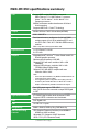
M2N-CM DVI specifications summary CPU Support AMD® socket AM2 /AM2+ processors/ AMD® Phenom™ FX / AMD Phenom™ processor/ Athlon™ 64 FX / Athlon™ 64 X2 / Athlon™ 64 / Sempron processors AMD64 architecture enables simultaneous 32-bit and 64-bit computing Supports AMD Cool ‘n’ Quiet™ Technology Chipset Nvidia® GeForce® 7025 / nForce 630a (MCP68S) System bus 2000 / 1600 MT/s Memory Dual-channel memory architecture 2 x 240-pin DIMM sockets support up to 4 GB of unbufferred ECC and non-ECC 1066* / 800
M2N-CM DVI specifications summary BIOS features 8 Mb Flash ROM, AMI BIOS, PnP, DMI2.0, WfM2.0, SM BIOS 2.5 Storage 1 x Ultra DMA 133 / 100 interface 4 x Serial ATA 3 Gb/s hard disk drives supporting RAID 0, RAID 1, RAID 5, RAID 10, and JBOD configuration ASUS Special Features ASUS Q-Fan ASUS CrashFree BIOS 3 ASUS EZ Flash 2 ASUS MyLogo 2™ Rear panel I/O 1 x LAN (RJ-45) port 1 x DVI port 4 x USB 2.0 / 1.
xii
This chapter describes the motherboard features and the new technologies it supports.
1.1 Welcome! Thank you for buying an ASUS® M2N-CM DVI motherboard! The motherboard delivers a host of new features and latest technologies, making it another standout in the long line of ASUS quality motherboards! Before you start installing the motherboard, and hardware devices on it, check the items in your package with the list below. 1.2 Package contents Check your motherboard package for the following items.
64-bit CPU support 64-bit computing, the technology to replace 32-bit architecture, delivers advanced system performance, faster memory access and increased productivity. This motherboard provides excellent compatibility and flexibility by supporting either 64-bit or 32-bit architecture. NVIDIA® GeForce™ 7025+nForce™ 630a Integrated NVIDIA® GeForce™ 7Series Shader mpdel 3.0 DirectX 9.0 graphics processor.
Serial ATA 3Gb/s technology This motherboard supports next-generation SATA hard drives based on the new SATA 3Gb/s storage specification.Allows RAID 0, RAID 1,RAID 10,RAID 5 and JBOD configurations for four SATA connectors.
1.3.2 Innovative ASUS features ASUS Q-Fan technology ASUS Q-Fan technology intelligently adjusts CPU fan speeds according to system loading to ensure quiet, cool and efficient operation. ASUS CrashFree BIOS 3 The ASUS CrashFree BIOS 3 allows users to restore corrupted BIOS data from a disk containing the BIOS file. This utility saves users the cost and hassle of buying a replacement BIOS chip. ASUS EZ Flash 2 EZ Flash 2 is a user-friendly BIOS update utility.
1.4 Before you proceed Take note of the following precautions before you install motherboard components or change any motherboard settings. • Unplug the power cord from the wall socket before touching any component. • Use a grounded wrist strap or touch a safely grounded object or a metal object, such as the power supply case, before handling components to avoid damaging them due to static electricity • Hold components by the edges to avoid touching the ICs on them.
1.5 Motherboard overview 1.5.1 Motherboard layout 21.1cm (8.3in) M2N-CM DVI LPT NVIDIA MCP68S PCI1 SATA4 SB_PWR SATA2 CR2032 3V Lithium Cell CMOS Power SATA3 COM1 SATA1 PCIEX16 CLRTC Super I/O EATXPWR CHA_FAN CPU_FAN CD AUDIO 24.4cm (9.
1.5.2 Placement direction When installing the motherboard, ensure that you place it into the chassis in the correct orientation. The edge with external ports goes to the rear part of the chassis as indicated in the image below. 1.5.3 Screw holes Place six (6) screws into the holes indicated by circles to secure the motherboard to the chassis. Do not overtighten the screws! Doing so can damage the motherboard.
1.6 Central Processing Unit (CPU) The motherboard comes with a 940-pin AM2/AM2+ socket designed for the AMD Socket AM2+ AMD Phenom™FX / Phenom™ / Athlon™ 64 / Sempron™ processor or for Socket AM2 Athlon 64 FX / Athlon 64 x2 /Athlon 64 / Semprom processor. The AM2/AM2+ socket has a different pinout from the 940-pin socket designed for the AMD Opteron™ processor. Ensure that you use a CPU is designed for the AM2/AM2+ socket. The CPU fits in only one correct orientation.
3. Position the CPU above the socket such that the CPU corner with the gold triangle matches the socket corner with a small triangle. 4. Carefully insert the CPU into the socket until it fits in place. Small triangle Gold triangle The CPU fits only in one correct orientation. DO NOT force the CPU into the socket to prevent bending the pins and damaging the CPU! 5. 6. 7. When the CPU is in place, push down the socket lever to secure the CPU.
1.6.2 Installing the heatsink and fan The AMD Phenom™FX / Phenom™/ Athlon™ 64 X2 / Athlon™ FX / Athlon™ 64 / Sempron™ processor require a specially designed heatsink and fan assembly to ensure optimum thermal condition and performance. Ensure that you use only qualified heatsink and fan assembly. Follow these steps to install the CPU heatsink and fan. 1. Place the heatsink on top of the installed CPU, making sure that the heatsink fits properly on the retention module base.
2. Attach one end of the retention bracket to the retention module base. 3. Align the other end of the retention bracket (near the retention bracket lock) to the retention module base. A clicking sound denotes that the retention bracket is in place. Ensure that the fan and heatsink assembly perfectly fits the retention mechanism module base. Otherwise, you cannot snap the retention bracket in place. 4.
1.7 System memory 1.7.1 Overview The motherboard comes with two Double Data Rate 2 (DDR2) Dual Inline Memory Modules (DIMM) sockets. A DDR2 module has the same physical dimensions as a DDR DIMM but has a 240-pin footprint compared to the 184-pin DDR DIMM. DDR2 DIMMs are notched differently to prevent installation on a DDR DIMM socket.
• You may install varying memory sizes in Channel A and Channel B. The system maps the total size of the lower-sized channel for the dual-channel configuration. Any excess memory from the higher-sized channel is then mapped for single-channel operation. • Always install DIMMs with the same CAS latency. For optimum compatibility, it is recommended that you obtain memory modules from the same vendor. • If you are using a Windows 32-bit version operating system (e.g.
Qualified Vendors Lists (QVL) DDR2-800 MHz capability Size Vendor Model CL Brand SS/ DS Component DIMM support A* B* 1G Kingston KVR800D2N5/1G N/A Samsung DS K4T51083QC-ZCE7 • • 1G Kingston KHX6400D2LL/1G N/A Kingston DS Heat-Sink Package • • 512MB Kingston KHX6400D2LLK2/1GN N/A Kingston SS Heat-Sink Package • • 512MB Kingston KVR800D2N5/512 N/A Promos SS V59C1512804QCF25SY032406PECPA • • 1G Kingston KHX6400D2K2/2G N/A Kingston DS Heat-Sink Package • • 1
Qualified Vendors Lists (QVL) DDR2-667 MHz capability Size Vendor 256MB Kingston 256MB Model CL Brand SS/ DS Component DIMM support A* B* KVR667D2N5/256 N/A Kingston SS D3216TLSAKL3U • • Kingston KVR667D2N5/256 N/A Infineon SS HYB18T256800AF3SW65 33154 • • 512MB Kingston KVR667D2N5/512 N/A Elpida SS E5108AGBG-6E-E • • 1G Kingston KVR667D2N5/1G N/A Kingston DS D6408TEBGGL3U • • 1G Kingston KVR667D2N5/1G N/A Elpida DS E5108AGBG-6E-E • • 512MB Samsung KR
Qualified Vendors Lists (QVL) DDR2-667 MHz capability Size Vendor Model CL Brand SS/ DS Component DIMM support A* B* 512MB ADATA M20EL5G3H3160B1C0Z N/A Elpida SS E5108AE-6E-E • • 512MB ADATA M20AD5G3H3166I1C52 N/A ADATA SS AD29608A8A-3EG20648 • • 512MB ADATA M20AD5G3H3166I1C52 N/A ADATA SS AD29608A8A-3EG20718 • • 1G ADATA M2OAD5G3I4176I1C52 N/A ADATA DS AD29608A8A-3EG20645 • • 2G ADATA M2OAD5H3J4170I1C53 N/A ADATA DS AD20908A8A-3EG 30724 • • 512MB VDATA
Qualified Vendors Lists (QVL) DDR2-533 MHz capability Size Vendor Model CL Brand SS/ DS Component DIMM support A* B* 512MB Elpida EBE51UD8ABFA-5C-E N/A Elpida SS E5108AB-5C-E • • 512MB Transcend 512MB DDR2 533 ECC N/A Micron SS 6ND22D9GCT(ECC) • • 512MB Kingmax KLBC28F-A8KB4 N/A Kingmax SS KKEA88B4IAK-37 • • 256MB Kingmax KLBB68F-36EP4 N/A Elpida SS E5116AB-5C-E • • 512MB Kingmax KLBC28F-A8EB4 N/A Elpida SS E5108AE-5C-E • • 512MB ADATA M2OAD2G3H3166I1B
1.7.3 Installing a DIMM Ensure to unplug the power supply before adding or removing DIMMs or other system components. Failure to do so may cause severe damage to both the motherboard and the components. 1. 2. 3. 2 Unlock a DIMM socket by pressing the retaining clips outward. 3 DDR2 DIMM notch Align a DIMM on the socket such that the notch on the DIMM matches the break on the socket. Firmly insert the DIMM into the socket until the retaining clips snap back in place and the DIMM is properly seated.
1.8 Expansion slots In the future, you may need to install expansion cards. The following sub‑sections describe the slots and the expansion cards that they support. Ensure to unplug the power cord before adding or removing expansion cards. Failure to do so may cause you physical injury and damage motherboard components. 1.8.1 Installing an expansion card To install an expansion card: 1. 2. 3. 4. 5. 6.
Interrupt assignments IRQ 0 1 4 6 8 9 13 10 20 20 21 21 22 22 23 Standard function High precision event timer Standard 101/102-Key or Microsoft Natural PS/2 keyboard Communications Port (COM1)* Standard floppy disk controller High precision event timer Microsoft ACPI-Compliant System Numeric data processor NVIDIA nForce PCI System Management NVIDIA Network Bus Enumerator Standard Enhanced PCI to USB Host Controller Standard Enhanced PCI to USB Host Controller Standard Dual Channel PCI IDE Controller Micros
1.8.3 PCI slots The PCI slots support cards such as a LAN card, SCSI card, USB card, and other cards that comply with PCI specifications. The figure shows a LAN card installed on a PCI slot. 1.8.4 PCI Express x16 slot This motherboard has supports PCI Express x16 graphic cards that comply with PCI Express specifications. The figure shows a graphics card installed on the PCI Express x16 slot.
1.9 1. Jumpers Clear RTC RAM (CLRTC) This jumper allows you to clear the Real Time Clock (RTC) RAM in CMOS. You can clear the CMOS memory of date, time, and system setup parameters by erasing the CMOS RTC RAM data. The onboard button cell battery powers the RAM data in CMOS, which include system setup information such as system passwords. To erase the RTC RAM: 1. Turn OFF the computer and unplug the power cord. 3. Move the jumper cap from pins 1-2 (default) to pins 2-3.
2. USB device wake-up (3-pin PS2_USBPW1-4, USBPW5-8, USBPW9-12) Set these jumpers to +5V to wake up the computer from S1 sleep mode (CPU stopped, DRAM refreshed, system running in low power mode) using the connected USB devices. Set to +5VSB to wake up from S3 and S4 sleep modes. The USBPW1-4 jumpers are for the rear USB ports. The USBPW5-8 and USBPW910 jumpers are for the internal USB connectors that you can connect to additional USB ports.
1.10 Connectors 1.10.1 Rear panel connectors 1 13 1. 2. 3. 3 2 12 11 10 6. 8 7 Video Graphics Adapter (VGA) port. This 15-pin port is for a VGA monitor or other VGA-compatible devices. LAN (RJ-45) port. Supported by Marvell Gigabit LAN controller, this port allows Gigabit connection to a Local Area Network (LAN) through a network hub. Refer to the table below for the LAN port LED indications. Activity/Link LED Status Description OFF No link ORANGE Linked BLINKING Data activity 5.
Refer to the audio configuration table below for the function of the audio ports in 2, 4, 6, or 8-channel configuration. Audio 2, 4, 6, or 8-channel configuration Headset 2-channel Line In Line Out Mic In – – – Port Light Blue Lime Pink Orange Black Gray 4-channel 6-channel 8-channel Line In Front Speaker Out Mic In – Rear Speaker Out – Line In Front Speaker Out Mic In Center/Subwoofer Rear Speaker Ou – Line In Front Speaker Out Mic In Center/Subwoofer Rear Speaker Out Side Speaker Out 10. USB 2.
1.10.2 1. Internal connectors Floppy disk drive connector (34-1 pin FLOPPY) This connector is for the provided floppy disk drive (FDD) signal cable. Insert one end of the cable to this connector, then connect the other end to the signal connector at the back of the floppy disk drive. Pin 5 on the connector is removed to prevent incorrect cable connection when using an FDD cable with a covered Pin 5. R M2N-CM DVI FLOPPY PIN1 NOTE: Orient the red markings on the floppy ribbon cable to PIN 1.
3. IDE connectors (40-1 pin PRI_IDE) The onboard IDE connector is for an Ultra DMA 133/100/66 signal cable. There are three connectors on each Ultra DMA 133/100/66 signal cable: blue, black, and gray. Connect the blue connector to the motherboard’s IDE connector, then select one of the following modes to configure your device(s).
4. Serial ATA connectors (7-pin SATA1, SATA2, SATA3, SATA4) These connectors are for the Serial ATA signal cables for Serial ATA 3Gb/s hard disk and optical disk drives. The Serial ATA 3Gb/s is backward compatible with Serial ATA 1.5Gb/s specification. The data transfer rate of the Serial ATA 3Gb/s is faster than the standard parallel ATA with 133 MB/s (Ultra DMA133).
5. CPU and Chassis Fan connectors (4-pin CPU_FAN, 3-pin CHA_FAN) The fan connectors support cooling fans of 350mA~740mA (8.88W max.) or a total of 1A~2.22A (26.64W max.) at +12V. Connect the fan cables to the fan connectors on the motherboard, ensuring that the black wire of each cable matches the ground pin of the connector. Do not forget to connect the fan cables to the fan connectors. Insufficient air flow inside the system may damage the motherboard components.
USB connectors (10-1 pin USB56, USB78, USB910, USB 1112) These connectors are for USB 2.0 ports. Connect the USB module cable to any of these connectors, then install the module to a slot opening at the back of the system chassis. These USB connectors comply with USB 2.0 specification that supports up to 480 Mbps connection speed. M2N-CM DVI USB 2.
9. Serial port connectors (10-1 pin COM1) The connector is for a serial (COM) port. Connect the serial port module cable to the connector, then install the module to a slot opening at the back of the system chassis. The serial port bracket (COM1) is purchased separately. COM1 PIN1 R M2N-CM DVI M2N-CM DVI COM Port Connector 10.
11. ATX power connectors (24-pin ATX-PWRGD, 4-pin ATX12V) These connectors are for an ATX power supply. The plugs from the power supply are designed to fit these connectors in only one orientation. Find the proper orientation and push down firmly until the connectors completely fit.
12. LPT connector The LPT (Line Printing Terminal) connector supports devices such as a printer. LPT standardizes as IEEE 1284, which is the parallel port interface on IBM PC-compatible computers. LPT GND GND GND GND GND GND GND GND SLIN# INIT# ERR# AFD 1 R M2N-CM DVI SLCT PE BUSY ACK# PD7 PD6 PD5 PD4 PD3 PD2 PD1 PD0 STB# M2N-CM DVI Parallel Port Connector 13. Speaker connector (4-pin SPEAKER) This connector is for the chassis-mounted system warning speaker.
14. System panel connector (10-1 pin PANEL) This connector supports several chassis-mounted functions. PWR BTN PLED+ PLEDPWR GND PLED F_PANEL IDELED+ IDELEDGround Reset R M2N-CM DVI +HDLED RESET M2N-CM DVI System Panel Connector • • • • System power LED (2-pin PLED) This 2-pin connector is for the system power LED. Connect the chassis power LED cable to this connector. The system power LED lights up when you turn on the system power, and blinks when the system is in sleep mode.
1-36 Chapter 1: Product introduction
This chapter tells how to change the system settings through the BIOS Setup menus. Detailed descriptions of the BIOS parameters are also provided.
2.1 Managing and updating your BIOS The following utilities allow you to manage and update the motherboard Basic Input/Output System (BIOS) setup. 1. 2. 3. 4. ASUS EZ Flash 2: Updates the BIOS using a floppy disk, USB Flash, or the motherboard support CD during POST. ASUS AFUDOS: Updates the BIOS in DOS mode using a bootable floppy disk. ASUS CrashFree BIOS 3: Updates the BIOS using a bootable floppy disk, USB flash disk or the motherboard support CD when the BIOS file fails or gets corrupted.
2.1.2 ASUS EZ Flash 2 utility The ASUS EZ Flash 2 feature allows you to update the BIOS without having to go through the long process of booting from a floppy disk and using a DOS‑based utility. The EZ Flash 2 utility is built-in the BIOS chip so it is accessible by pressing + during the Power-On Self-Test (POST). To update the BIOS using EZ Flash 2: 1. 2. 3. Visit the ASUS website (www.asus.com) to download the latest BIOS file for the motherboard.
2.1.3 AFUDOS utility The AFUDOS utility allows you to update the BIOS file in DOS environment using a bootable floppy disk with the updated BIOS file. This utility also allows you to copy the current BIOS file that you can use as backup when the BIOS fails or gets corrupted during the updating process. Copying the current BIOS To copy the current BIOS file using the AFUDOS utility: 1. 2. • Make sure that the floppy disk is not write-protected and has at least 1024KB free space to save the file.
Updating the BIOS file To update the BIOS file using the AFUDOS utility: 1. Visit the ASUS website (www.asus.com) and download the latest BIOS file for the motherboard. Save the BIOS file to a bootable floppy disk. Write the BIOS filename on a piece of paper. You need to type the exact BIOS filename at the DOS prompt. 2. 3. Copy the AFUDOS utility (afudos.exe) from the motherboard support CD to the bootable floppy disk you created earlier.
2.1.4 ASUS CrashFree BIOS 3 utility The ASUS CrashFree BIOS 3 is an auto recovery tool that allows you to restore the BIOS file when it fails or gets corrupted during the updating process. You can update a corrupted BIOS file using the motherboard support CD , the floppy disk or the USB flash disk that contains the updated BIOS file. • Prepare the motherboard support CD, the floppy disk or the USB flash disk containing the updated motherboard BIOS before using this utility.
Recovering the BIOS from the support CD To recover the BIOS from the support CD: 1. Remove any floppy disk from the floppy disk drive, then turn on the system. 3. The utility displays the following message and automatically checks the floppy disk for the original or updated BIOS file. 2. Insert the support CD to the optical drive. Bad BIOS checksum. Starting BIOS recovery... Checking for floppy...
2.1.5 ASUS Update utility The ASUS Update is a utility that allows you to manage, save, and update the motherboard BIOS in Windows® environment. The ASUS Update utility allows you to: • Save the current BIOS file • Update the BIOS from an updated BIOS file • • • Download the latest BIOS file from the Internet Update the BIOS directly from the Internet, and View the BIOS version information. This utility is available in the support CD that comes with the motherboard package.
Updating the BIOS through the Internet To update the BIOS through the Internet: 1. Launch the ASUS Update utility from the Windows® desktop by clicking Start > Programs > ASUS > ASUSUpdate > ASUSUpdate. The ASUS Update main window appears. 2. Select Update BIOS from the Internet option from the drop‑down menu, then click Next. ASUS M2N-CM DVI 3. Select the ASUS FTP site nearest you to avoid network traffic, or click Auto Select. Click Next.
4. 5. From the FTP site, select the BIOS version that you wish to download. Click Next. Follow the screen instructions to complete the update process. The ASUS Update utility is capable of updating itself through the Internet. Always update the utility to avail all its features. Updating the BIOS through a BIOS file To update the BIOS through a BIOS file: 1. Launch the ASUS Update utility from the Windows® desktop by clicking Start > Programs > ASUS > ASUSUpdate > ASUSUpdate.
2.2 BIOS setup program This motherboard supports a programmable Low-Pin Count (LPC) chip that you can update using the provided utility described in section “2.1 Managing and updating your BIOS.” Use the BIOS Setup program when you are installing a motherboard, reconfiguring your system, or prompted to“Run Setup.” This section explains how to configure your system using this utility. Even if you are not prompted to use the Setup program, you can change the configuration of your computer in the future.
2.2.1 BIOS menu screen Menu items Menu bar Configuration fields System Time System Date Legacy Diskette A [23: 18 : 17] [Sun 01/13/2002] [1.44M,3.5in.] General help Use [ENTER], [TAB] or [SHIFT-TAB] to select a field. Use [+] or [-] to configure system time. IDE Configuration Primary IDE Master Primary IDE Slave SATA1 SATA2 SATA3 SATA4 : : : : : : [Not [Not [Not [Not [Not [Not Detected] Detected] Detected] Detected] Detected] Detected] System Information Sub-menu items 2.2.
Some of the navigation keys differ from one screen to another. 2.2.4 Menu items The highlighted item on the menu bar displays the specific items for that menu. For example, selecting Main shows the Main menu items. The other items (Advanced, Power, Boot, and Exit) on the menu bar have their respective menu items. 2.2.5 Sub-menu items A solid triangle before each item on any menu screen means that the iteam has a sub-menu. To display the sub-menu, select the item and press . 2.2.
2.3 Main menu When you enter the BIOS Setup program, the Main menu screen appears, giving you an overview of the basic system information. Refer to section “2.2.1 BIOS menu screen” for information on the menu screen items and how to navigate through them. System Time System Date Legacy Diskette A [23: 20 : 11] [Sun 01/13/2002] [1.44M,3.5in.
2.3.4 IDE Configuration The items in this menu allow you to set or change the configurations for the IDE devices installed in the system. Select an item then press if you wish to configure the item. IDE Configuration Onboard IDE Controller [Enabled] Serial-ATA Devices [Enabled] SATA Mode select [SATA Mode] Disabled: disables the integrated IDE Controller. Enabled: enable the integrated IDE Controller.
2.3.5 Primary IDE Master/Slave While entering Setup, the BIOS automatically detects the presence of IDE devices. There is a separate sub-menu for each IDE device. Select a device item then press to display the IDE device information.
PIO Mode [Auto] Selects the PIO mode. Configuration options: [Auto] [0] [1] [2] [3] [4] DMA Mode [Auto] Selects the DMA mode. Configuration options: [Auto] SMART Monitoring [Auto] Enables or disables the S.M.A.R.T. (Self Monitoring and Reporting Technology) capability of your hard drive. This features allows your system to report read/write errors of the hard drive and to issue warnings when a third party hardware monitor utility is installed.
2.3.6 SATA1, SATA2, SATA3, and SATA4 While entering Setup, the BIOS automatically detects the presence of SATA devices. There is a separate sub-menu for each SATA device. Select a device item then press to display the SATA device information. SATA1 Device : Hard Disk Vendor : ST380011AS Size : 80.
DMA Mode [Auto] Selects the DMA mode. Configuration options: [Auto] [SWDMA0] [SWDMA1] [SWDMA2] [MWDMA0] [MWDMA1] [MWDMA2] [UDMA0] [UDMA1] [UDMA2] [UDMA3] [UDMA4] [UDMA5] [UDMA6] SMART Monitoring [Auto] Enables or disables the S.M.A.R.T. (Self Monitoring and Reporting Technology) capability of your hard drive. This features allows your system to report read/write errors of the hard drive and to issue warnings when a third party hardware monitor utility is installed.
2.4 Advanced menu The Advanced menu items allow you to change the settings for the CPU and other system devices. Take caution when changing the settings of the Advanced menu items. Incorrect field values can cause the system to malfunction. JumperFree Configuration CPU Configuration Chipset Onboard Devices Configuration PCIPnP USB Configuration 2.4.1 Adjust System Frequency/Voltage etc.
The following item appears only when the AI Overclocking item is set to [MANUAL]. CPU Frequency (MHz) [200.0] Displays the frequency sent by the clock generator to the system bus and PCI bus. The value of this item is auto-detected by the BIOS. Use the < > and < > keys to adjust the CPU frequency. Refer to the table below for the correct Front Side Bus and CPU External Frequency settings. The following two items appear only when the AI Overclocking item is set to [Overclock Profile].
2.4.2 CPU Configuration CPU Configuration Module Version: 13.15 AGESA Version: 3.1.1.0 Physical Count: 1 Logical Count: 2 AMD Athlon(tm) Processor 3200+ Revision: F2 Cache L1: 256KB Cache L2: 1024KB Speed : 2000MHz Current FSB Multiplier: 9x Maximum FSB Multiplier: 9x Able to Change Freq. : Yes uCode Patch Level : 0x62 GART Error Reporting Microcode Updation Secure Virtual Machine Mode Cool’n’Quiet This option should remain disabled for the normal operation.
2.4.3 Chipset The Chipset menu allows you to change the advanced chipset settings. Select an item then press to display the sub-menu. Advanced Chipset Setting Memory Options & Information WARNING: Setting wrong values in below sections may cause system to malfunction.
Enable Clock to All DIMMs [Disabled] Enables or disables clock to all DIMMs. Configuration options: [Disabled] [Enabled] MemClk Tristate C3/ALTVID [Disabled] Enables or disables the MemClk Tristate C3/ALTVID. Configuration options: [Disabled] [Enabled] Memory Hole Remapping [Enabled] Enables or disables the memory remapping around memory hole. Configuration options: [Disabled] [Enabled] Power Down Enable [Enabled] Enables or disables the DDR power down mode.
ECC Configuration ECC Configuration ECC Mode DRAM ECC Enable DRAM SCRUB REDIRECT 4-Bit ECC Mode DRAM BG Scrub Data Cache BG Scrub L2 Cache BG Scrub L3 Cache BG Scrub [Disabled] [Disabled] [Disabled] [Disabled] [Disabled] [Disabled] [Disabled] [Disabled] DRAM ECC allows hardware to report and correct memory errors automatically maintaining system integrity. ECC Enable [Disabled] Enables or disables the DRAM ECC that allows the hardware to report and correct memory errors automatically.
SouthBridge Configuration SouthBridge chipset Configuration Primary Graphics Adapter iGPU Frame Buffer Detect iGPU Frame Buffer Size AZALIA AUDIO Front Panel Select OnBoard LAN OnBoard LAN Boot ROM SouthBridge ACPI HPET TABLE [PCIE-> PCI -> IGP] [Auto] [128MB] [Enabled] [HD Audio] [Auto] [Disabled] [Enabled] Display Device Priority, from high to low Primary Graphics Adapter [PCIE-> PCI -> IGP] Display Device Priority, from high to low.
2.4.4 Onboard Devices Configuration Configure ITE8712 Super IO Chipset Serial Port1 Address [3F8/IRQ4] Parallel Port Address [378] Parallel Port Mode [Normal] Parallel Port IRQ [IRQ7] Allows BIOS to select Serial Port1 Base Address. Serial Port1 Address [3F8/IRQ4] Allows you to select the Serial Port1 base address. Configuration options: [Disabled] [3F8/IRQ4][2F8/IRQ3] [3E8/IRQ4] [2E8/IRQ3] Parallel Port Address [378] Allows you to select the Parallel Port base addresses.
2.4.5 PCI PnP The PCI PnP menu items allow you to change the advanced settings for PCI/PnP devices. The menu includes setting IRQ and DMA channel resources for either PCI/PnP or legacy ISA devices, and setting the memory size block for legacy ISA devices. Take caution when changing the settings of the PCI PnP menu items. Incorrect field values can cause the system to malfunction. Advanced PCI/PnP Settings WARNING: Setting wrong values in below sections may cause system to malfunction.
IRQ-xx assigned to [PCI Device] When set to [PCI Device], the specific IRQ is free for use of PCI/PnP devices. When set to [Reserved], the IRQ is reserved for legacy ISA devices. Configuration options: [PCI Device] [Reserved] 2.4.6 USB Configuration The items in this menu allows you to change the USB-related features. Select an item then press to display the configuration options. USB Configuration Options Module Version - 2.24.1-13.4 Enable Disable USB Devices Enabled: 1 Drive USB 1.
USB 2.0 Controller Mode [HiSpeed] Allows you to configure the USB 2.0 controller in HiSpeed (480 Mbps) or Full Speed (12 Mbps). Configuration options: [Full Speed] [HiSpeed] USB Mass Storage Device Configuration USB Mass Storage Device Configuration USB Mass Storage Reset Delay Device #1 Emulation Type Netac [20 Sec] [Auto] Number of seconds POST waits for the USB mass storage device after start unit command.
2.5 Power menu The Power menu items allow you to change the settings for the Advanced Configuration and Power Interface (ACPI) and the Advanced Power Management (APM). Select an item then press to display the configuration options. Suspend Mode ACPI 2.0 Support ACPI APIC support [Auto] [Disabled] [Enabled] Select the ACPI state used for System Suspend. APM Configuration Hardware Monitor 2.5.
2.5.4 APM Configuration APM Configuration Restore on AC Power Loss [Power Off] Power Power Power Power [Disabled] [Disabled] [Disabled] [Disabled] On On On On By By By By PCI/PCIE Device Ring PS/2 KB/MS RTC Alarm Go into On/Off or Suspend when Power button is pressed. Restore on AC Power Loss [Power Off] When set to Power Off, the system goes into off state after an AC power loss. When set to Power On, the system goes on after an AC power loss.
2.5.5 Hardware Monitor Hardware Monitor CPU Temperature CPU Temperature [41ºC/105.5ºF] CPU Fan Speed Chassis Fan Speed [3308RPM] [N/A] VCORE Voltage 3.3V Voltage 5V Voltage 12V Voltage [ 1.232V] [ 3.328V] [ 4.915V] [11.916V] Smart Q-FAN Function [Disabled] CPU Temperature [xxxºC/xxxºF] MB Temperature [xxxºC/xxxºF] The onboard hardware monitor automatically detects and displays the motherboard and CPU temperatures. Select Ignored if you do not wish to display the detected temperatures.
2.6 Boot menu The Boot menu items allow you to change the system boot options. Select an item then press to display the sub-menu. Specifies the Boot Device Priority sequence. Boot settings Boot Device Priority A virtual floopy disk drive (Floppy Drive B:) may appear when you set the CD-ROM drive as the first boot device. Boot Settings Configuration Security Enter F1 F10 ESC 2.6.
2.6.3 Boot Settings Configuration Boot Settings Configuration Quick Boot Full Screen Logo AddOn ROM Display Mode Bootup Num-Lock PS/2 Mouse Support Wait For ‘F1’ If Error Hit ‘DEL’ Message Display Interrupt 19 Capture [Enabled] [Enabled] [Force BIOS] [On] [Auto] [Enabled] [Enabled] [Disabled] Quick Boot [Enabled] Allows BIOS to skip certain tests while booting. This will decrease the time needed to boot the system.
Interrupt 19 Capture [Disabled] When set to [Enabled], this function allows the option ROMs to trap Interrupt 19. Configuration options: [Disabled] [Enabled] 2.6.4 Security The Security menu items allow you to change the system security settings. Select an item then press to display the configuration options.
Security Settings Supervisor Password User Password : Not Installed : Not Installed Change Supervisor Password User Access Level Change User Password Clear User Password Password Check [Full Access] [Setup] +F1 F10 ESC Select Screen Select Item Change Option General Help Save and Exit Exit User Access Level [Full Access] This item allows you to select the access restriction to the Setup items.
2.7 Tools menu Press ENTER to run the utility to select and update BIOS. This utility doesn’t support: 1. NTFS format ASUS EZ Flash 2 ASUS EZ Flash 2 Allows you to run ASUS EZ Flash 2. When you press , a confirmation message appears. Use the left/right arrow key to select between [Yes] or [No], then press to confirm your choice. ASUSTek EZ Flash 2 BIOS ROM Utility V3.
2.8 Exit menu The Exit menu items allow you to load the optimal or failsafe default values for the BIOS items, and save or discard your changes to the BIOS items. Exit Options Exit & Save Changes Exit & Discard Changes Discard Changes Exit system setup after saving the changes. F10 key can be used for this operation. Load Setup Defaults Pressing does not immediately exit this menu. Select one of the options from this menu or from the legend bar to exit.
This chapter describes the contents of the support CD that comes with the motherboard package.
3.1 Installing an operating system This motherboard supports Windows® 32-bit XP / 32-bit Vista / 64-bit XP / 64-bit Vista operating systems (OS). Always install the latest OS version and corresponding updates to maximize the features of your hardware. 3.2 • Motherboard settings and hardware options vary. Use the setup procedures presented in this chapter for reference only. Refer to your OS documentation for detailed information.
3.2.2 Drivers menu The drivers menu shows the available device drivers if the system detects installed devices. Install the necessary drivers to activate the devices. ASUS InstAll - Installation Wizard for Drivers Launches the ASUS InstallAll drivers installation wizard. Nvidia Chipset Program Driver Installs the Nvidia chipset program driver. VIA Audio Driver Installs the VIA audio driver and application. AMD Cool ‘n’ Quiet Driver Installs the AMD Cool ‘n’ Quiet driver.
3.2.3 Utilities menu The Utilities menu shows the applications and other software that the motherboard supports. ASUS InstAll - Installation Wizard for Utilities Launches the ASUS InstallAll utilities installation wizard. ASUS PC Probe II This smart utility monitors the fan speed, CPU temperature, and system voltages, and alerts you of any detected problems. This utility helps you keep your computer in healthy operating condition.
You can also install the following utilities from the ASUS Superb Software Library CD. ADOBE Acrobat Reader V7.0 Installs the Adobe® Acrobat® Reader that allows you to open, view, and print documents in Portable Document Format (PDF). Microsoft DirectX 9.0c Installs the Microsoft® DirectX 9.0c driver. The Microsoft DirectX® 9.0c is a multimedia technology that enhances computer graphics and sound.
3.2.4 Make Disk menu The Make Disk menu allows you to make a RAID driver disk. NVIDIA 64bit Vista SATA RAID Driver Allows you to create the NVIDIA SATA RAID Driver disk for 64-bit Windows Vista Operating System (OS). NVIDIA 32bit Vista SATA RAID Driver Allows you to create the NVIDIA SATA RAID Driver disk for 64-bit Windows Vista Operating System (OS). NVIDIA 32bit XP SATA RAID Driver Allows you to create the NVIDIA SATA RAID Driver disk for 32-bit Windows XP Operating System (OS).
3.2.5 Manual menu The Manual menu contains a list of supplementary user manuals. Click an item to open the folder of the user manual. Most user manual files are in Portable Document Format (PDF). Install the Adobe® Acrobat® Reader from the Utilities menu before opening a user manual file. 3.2.6 ASUS Contact information Click the Contact tab to display the ASUS contact information. You can also find this information on the inside front cover of this user guide.
3.2.7 Other information The icons on the top right corner of the screen give additional information on the motherboard and the contents of the support CD. Click an icon to display the specified information. Motherboard Info Displays the general specifications of the motherboard. M2N-VM SE HDMI ASUS M2N-VM SE HDMI ACPI BIOS Revision 0105 10/29/07 Browse this CD Displays the support CD contents in graphical format.
Technical support Form Displays the ASUS Technical Support Request Form that you have to fill out when requesting technical support. Filelist Displays the contents of the support CD and a brief description of each in text format.
3-10 Chapter 3: Software support