Motherboard M3N78-AM
E4421 Second Edition V2 January 2009 Copyright © 2009 ASUSTeK Computer Inc. All Rights Reserved. No part of this manual, including the products and software described in it, may be reproduced, transmitted, transcribed, stored in a retrieval system, or translated into any language in any form or by any means, except documentation kept by the purchaser for backup purposes, without the express written permission of ASUSTeK Computer Inc. (“ASUS”).
Contents Notices.......................................................................................................... vi Safety information...................................................................................... vii About this guide......................................................................................... vii M3N78-AM specifications summary.......................................................... ix Chapter 1: Product introduction 1.1 Welcome!............................
Contents 1.10 Connectors.................................................................................. 1-18 1.10.2 Internal connectors..........................................................1-19 1.11 1.10.1 Rear panel connectors................................................... 1-18 Software support......................................................................... 1-25 1.11.1 1.11.2 Installing an operating system....................................... 1-25 Support DVD information......
Contents 2.4.5 2.5 2.4.6 2.5.1 Suspend Mode [Auto].................................................... 2-19 2.5.3 ACPI APIC Support [Enabled]........................................ 2-19 2.5.4 2.5.5 2.8 ACPI 2.0 Support [Disabled].......................................... 2-19 APM Configuration......................................................... 2-19 Hardware Monitor ......................................................... 2-20 Boot menu.........................................................
Notices Federal Communications Commission Statement This device complies with Part 15 of the FCC Rules. Operation is subject to the following two conditions: • This device may not cause harmful interference, and • This device must accept any interference received including interference that may cause undesired operation. This equipment has been tested and found to comply with the limits for a Class B digital device, pursuant to Part 15 of the FCC Rules.
Safety information Electrical safety • • • • • • To prevent electrical shock hazard, disconnect the power cable from the electrical outlet before relocating the system. When adding or removing devices to or from the system, ensure that the power cables for the devices are unplugged before the signal cables are connected. If possible, disconnect all power cables from the existing system before you add a device.
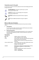
Conventions used in this guide To ensure that you perform certain tasks properly, take note of the following symbols used throughout this manual. DANGER/WARNING: Information to prevent injury to yourself when trying to complete a task. CAUTION: Information to prevent damage to the components when trying to complete a task. IMPORTANT: Instructions that you MUST follow to complete a task. NOTE: Tips and additional information to help you complete a task.
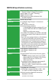
M3N78-AM specifications summary CPU AMD® Socket AM2+ / AM2 for AMD Phenom™FX / Phenom™ / Athlon™ / Sempron™ processors Supports AMD Cool ‘n’ Quiet™ Technology Supports CPU up to 125W AMD64 architecture enables simultaneous 32-bit and 64-bit computing Chipset NVIDIA® GeForce® 8200 System bus Up to 5200 MT/s HyperTransport™ 3.
M3N78-AM specifications summary USB 12 x USB 2.0/1.
Chapter 1 Product introduction 1.1 Welcome! Thank you for buying an ASUS® M3N78-AM motherboard! The motherboard delivers a host of new features and latest technologies, making it another standout in the long line of ASUS quality motherboards! Before you start installing the motherboard, and hardware devices on it, check the items in your package with the list below. 1.2 Package contents Check your motherboard package for the following items.
5200 MT/s HyperTransport™ 3.0 support HyperTransport™ 3.0 technology provides 2.6 times more bandwidth than HT1.0 that radically improves system efficiency for a smoother, faster computing environment. 64-bit CPU support 64-bit computing, the next generation technology to replace the current 32-bit architecture, delivers advanced system performance, faster memory access, and increased productivity.
PCI Express 2.0 support This motherboard supports the latest PCIe 2.0 devices for double speed and bandwidth which enhances system performance. Serial ATA 3Gb/s technology The motherboard supports next-generation SATA hard drives based on the new SATA 3Gb/s storage specification. The onboard Southbridge chipset allows RAID 0, RAID 1, RAID 0+1, RAID 5, and JBOD configurations for Serial ATA drives.
Green ASUS This motherboard and its packaging comply with the European Union’s Restriction on the use of Hazardous Substances (RoHS). This is in line with the ASUS vision of creating environment-friendly and recyclable products/packaging to safeguard consumers’ health while minimizing the impact on the environment. C.P.R. (CPU Parameter Recall) The BIOS C.P.R. feature automatically restores the CPU default settings when the system hangs due to overclocking failure. C.P.R.
1.4 Before you proceed Take note of the following precautions before you install motherboard components or change any motherboard settings. • Unplug the power cord from the wall socket before touching any component. • Before handling components, use a grounded wrist strap or touch a safely grounded object or a metal object, such as the power supply case, to avoid damaging them due to static electricity. • Hold components by the edges to avoid touching the ICs on them.
1.5 Motherboard overview 1.5.1 Placement direction 1.5.2 Screw holes When installing the motherboard, ensure that you place it into the chassis in the correct orientation. The edge with external ports goes to the rear part of the chassis as indicated in the image below. Place eight screws into the holes indicated by circles to secure the motherboard to the chassis. Do not overtighten the screws! Doing so can damage the motherboard. Place this side towards the rear of the chassis.
1.5.3 Motherboard layout 1 KB_USB56 2 21.8cm(8.6in) 3 4 CPU_FAN EATXPWR LAN1_USB12 24.4cm(9.6in) USB34 DDR2 DIMM_B1 (64bit, 240-pin module) VGA LPT SOCKET AM2+ DDR2 DIMM_A1 (64bit, 240-pin module) COM ATX12V SATA2 SATA4 SATA1 SATA3 NVIDIA® GeForce 8200 PCIEX1_1 Realtek 8211CL 5 SB_PWR PCIEX16 Lithium Cell CMOS Power M3N78-AM CLRTC PRI_IDE AUDIO SPEAKER PCI1 8Mb BIOS Super I/O 1 6 7 PCI2 ALC 662 SPDIF_OUT CD FLOPPY F_PANEL USB910 USB78 USB1112 AAFP 15 1.5.
1.6 Central Processing Unit (CPU) The motherboard comes with an AM2+ / AM2 socket designed for AMD® AM2+ / AM2 Phenom™ FX / Phenom / Athlon™ / Sempron™ processor. The AM2/AM2+ socket has a different pinout from the 940-pin socket designed for the AMD Opteron™ processor. Use a CPU that is designed for the AM2/AM2+ socket. 1.6.1 Installing the CPU To install a CPU: 1. Locate the CPU socket on the motherboard. M3N78-AM M3N78-AM CPU Socket AM2+ 2.
3. Position the CPU above the socket such that the CPU corner with the gold triangle matches the socket corner with a small triangle. 4. Carefully insert the CPU into the socket until it fits in place. The CPU fits only in one correct orientation. DO NOT force the CPU into the socket to prevent bending the pins and damaging the CPU! Small triangle Gold triangle 5. When the CPU is in place, push down the socket lever to secure the CPU. The lever clicks on the side tab to indicate that it is locked.
1.6.2 Installing the heatsink and fan Ensure that you use only AMD-certified heatsink and fan assembly. To install the CPU heatsink and fan: 1. Place the heatsink on top of the installed CPU, making sure that the heatsink fits properly on the retention module base. • The retention module base is already installed on the motherboard upon purchase. • You do not have to remove the retention module base when installing the CPU or installing other motherboard components.
3. Align the other end of the retention bracket to the retention module base. A clicking sound denotes that the retention bracket is in place. Ensure that the fan and heatsink assembly perfectly fits the retention mechanism module base, otherwise you cannot snap the retention bracket in place. 4. Push down the retention bracket lock on the retention mechanism to secure the heatsink and fan to the module base. 5.
1.7.2 Memory configurations You may install 256MB, 512MB, 1GB, 2GB, and 4GB unbuffered ECC/non-ECC DDR2 DIMMs into the DIMM sockets. • You may install varying memory sizes in Channel A and Channel B. The system maps the total size of the lower-sized channel for the dual-channel configuration. Any excess memory from the higher-sized channel is then mapped for single-channel operation. • Always install DIMMs with the same CAS latency.
DDR2-800MHz capability DIMM support Vendor Part No. Size SS/ DS CL Chip No. Chip Brand A* B* Kingston KHX6400D2LLK2/1GN 512MB SS N/A Heat-Sink Package Kingston • • Kingston KVR800D2N5/1G 1G DS N/A E5108AJBG-8E-E Elpida • • Samsung M378T2863QZS-CF7 1G SS 6 K4T1G084QQ-HCF7 Samsung • • Samsung M391T2863QZ3-CF7 1G SS 6 K4T1G084QQ-HCF7(ECC) Samsung • • Samsung M378T5263AZ3-CF7 4G DS N/A K4T2G084QA-HCF7 Samsung • • Qimonda HYS64T64000EU-2.
DDR2-533MHz capability Vendor Part No. Size SS/DS CL Chip No.
1.7.3 Installing a DIMM Unplug the power supply before adding or removing DIMMs or other system components. Failure to do so can cause severe damage to both the motherboard and the components. 2 1. Press the retaining clips outward to unlock a DDR2 DIMM socket. 2. Align a DIMM on the socket such that the notch on the DIMM matches the break on the socket. DDR2 DIMM notch 1 1 Unlocked retaining clip A DDR2 DIMM is keyed with a notch so that it fits in only one direction.
1.8 Expansion slots In the future, you may need to install expansion cards. The following sub‑sections describe the slots and the expansion cards that they support. Unplug the power cord before adding or removing expansion cards. Failure to do so may cause you physical injury and damage motherboard components. 1.8.1 Installing an expansion card To install an expansion card: 1.
1.9 1. Jumpers Clear RTC RAM (CLRTC) This jumper allows you to clear the Real Time Clock (RTC) RAM in CMOS. You can clear the CMOS memory of date, time, and system setup parameters by erasing the CMOS RTC RAM data. The onboard button cell battery powers the RAM data in CMOS, which include system setup information such as system passwords. CLRTC 1 M3N78-AM 2 2 3 Normal (Default) Clear RTC M3N78-AM Clear RTC RAM To erase the RTC RAM: 1. Turn OFF the computer and unplug the power cord. 2.
1.10 Connectors 1.10.1 Rear panel connectors 1 2 11 3 10 9 8 4 5 7 6 1. PS/2 Keyboard port (purple). This port is for a PS/2 keyboard / mouse. 2. Video Graphics Adapter (VGA) port. This 15-pin port is for a VGA monitor or other VGA-compatible devices. 3. LAN (RJ-45) port. This port allows Gigabit connection to a Local Area Network (LAN) through a network hub.
7. USB 2.0 ports 1 and 2. These two 4-pin Universal Serial Bus (USB) ports are available for connecting USB 2.0 devices. 8. USB 2.0 ports 3 and 4. These two 4-pin Universal Serial Bus (USB) ports are available for connecting USB 2.0 devices. 9. Video Graphics Adapter (VGA) port. This 15-pin port is for a VGA monitor or other VGA-compatible devices. 10. Serial port. This 9-pin COM1 port is for printing devices or other serial devices. 11. USB 2.0 ports 5 and 6.
2. Floppy disk drive connector (34-1 pin FLOPPY) This connector is for a Floppy Disk Drive (FDD) signal cable. Insert one end of the provided FDD cable to this connector, then connect the other end to the signal connector at the back of the floppy disk drive. Pin 5 on the connector is removed to prevent incorrect cable connection when using an FDD cable with a covered Pin 5. FLOPPY PIN1 M3N78-AM NOTE:Orient the red markings on the floppy ribbon cable to PIN 1. M3N78-AM Floppy disk drive connector 3.
4. ATX power connectors (24-pin EATXPWR, 4-pin ATX12V) These connectors are for an ATX power supply. The plugs from the power supply are designed to fit these connectors in only one orientation. Find the proper orientation and push down firmly until the connectors completely fit.
6. System panel connector (20-8 pin PANEL) This connector supports several chassis-mounted functions. PLED+ PLEDPWR GND PWR LED PWR BTN PIN 1 IDE_LED+ IDE_LEDGround Reset F_PANEL M3N78-AM HD_LED RESET M3N78-AM System panel connector • System power LED (2-pin PLED) This 2-pin connector is for the system power LED. Connect the chassis power LED cable to this connector. The system power LED lights up when you turn on the system power, and blinks when the system is in sleep mode.
USB connectors (10-1 pin USB78, USB910, USB1112) These connectors are for USB 2.0 ports. Connect the USB module cable to any of these connectors, then install the module to a slot opening at the back of the system chassis. These USB connectors comply with USB 2.0 specification that supports up to 480 Mbps connection speed.
Digital audio connector (4-1 pin SPDIF_OUT) SPDIFOUT GND This connector is for an additional Sony/Philips Digital Interface (S/PDIF) ports. +5V 10. M3N78-AM SPDIF_OUT M3N78-AM Digital audio connector The S/PDIF module is purchased separately. 11. CPU Fan connectors (4 pin CPU_FAN) The fan connector supports cooling fans of 350mA~740mA (8.88W max.) or a total of 1A~2.22A (26.64W max.) at +12V.
1.11 Software support 1.11.1 Installing an operating system This motherboard supports Windows® XP/Vista Operating Systems (OS). Always install the latest OS version and corresponding updates to maximize the features of your hardware. • Motherboard settings and hardware options vary. Use the setup procedures presented in this chapter for reference only. Refer to your OS documentation for detailed information.
1-26 ASUS M3N78-AM
Chapter 2 BIOS information 2.1 Managing and updating your BIOS Save a copy of the original motherboard BIOS file to a floppy disk or a USB flash disk in case you need to restore the BIOS in the future. Copy the original motherboard BIOS using the ASUS Update or AFUDOS utilities. 2.1.1 Creating a bootable floppy disk Create a bootable floppy disk using a different computer. To create a bootable floppy disk: 1. 2. Insert a formatted, high density 1.44MB floppy disk to the floppy disk drive.
2.1.2 ASUS Update utility The ASUS Update is a utility that allows you to manage, save, and update the motherboard BIOS in Windows® environment. • ASUS Update requires an Internet connection either through a network or an Internet Service Provider (ISP). • This utility is available in the support DVD that comes with the motherboard package. Installing ASUS Update To install ASUS Update: 1. Place the support DVD in the optical drive. The Drivers menu appears. 2.
2.1.3 ASUS EZ Flash 2 utility The ASUS EZ Flash 2 feature allows you to update the BIOS without having to use a bootable floppy disk or an OS‑based utility. Before using this utility, download the latest BIOS file from the ASUS website at www.asus. com. To update the BIOS using EZ Flash 2: 1. Insert the floppy/USB flash disk that contains the latest BIOS file to the floppy disk drive or the USB port, then launch EZ Flash 2. You can launch EZ Flash 2 in two ways. a.
2.1.4 AFUDOS utility The AFUDOS utility allows you to update the BIOS file in DOS environment using a bootable floppy disk. This utility also allows you to copy the current BIOS file that you can use as backup when the BIOS fails or gets corrupted during the updating process. • Ensure that you prepare two floppy disks: the bootable floppy disk and the floppy disk containing the AFUDOS utility and the latest BIOS file.
2.1.5 ASUS CrashFree BIOS 3 utility The ASUS CrashFree BIOS 3 is an auto recovery tool that allows you to restore the BIOS file when it fails or gets corrupted during the updating process. You can update a corrupted BIOS file using the motherboard support DVD, a floppy disk, or a USB flash disk that contains the updated BIOS file. • Prepare the motherboard support DVD, the floppy disk, or the USB flash disk containing the updated motherboard BIOS before using this utility.
2.2 BIOS setup program This motherboard supports a programmable Serial Peripheral Interface (SPI) chip that you can update using the provided utility described in section “2.1 Managing and updating your BIOS.” Use the BIOS Setup program when you are installing a motherboard, reconfiguring your system, or prompted to “Run Setup.” This section explains how to configure your system using this utility.
2.2.1 BIOS menu screen Menu bar Menu items Main Advanced Power BIOS SETUP UTILITY Boot Tools Exit System Time [19:34:30] System Date [Wed 08/27/2008] Legacy Diskette A [1.44M, 3.5 in.] Primary IDE Master Primary IDE Slave SATA1 SATA2 SATA3 SATA4 Storage Configuration General help Configuration fields :[Not :[Not :[Not :[Not :[Not :[Not Detected] Detected] Detected] Detected] Detected] Detected] System Information Use [ENTER], [TAB] or [SHIFT-TAB] to select a field.
2.2.3 Navigation keys At the bottom right corner of a menu screen are the navigation keys for that particular menu. Use the navigation keys to select items in the menu and change the settings. Some of the navigation keys differ from one screen to another. 2.2.4 Menu items 2.2.5 Submenu items 2.2.6 Configuration fields 2.2.7 General help 2.2.8 Pop-up window The highlighted item on the menu bar displays the specific items for that menu. For example, selecting Main shows the Main menu items.
2.3 Main menu When you enter the BIOS Setup program, the Main menu screen appears, giving you an overview of the basic system information. Refer to section “2.2.1 BIOS menu screen” for information on the menu screen items and how to navigate through them. Main Advanced Power BIOS SETUP UTILITY Boot Tools Exit System Time [19:34:30] System Date [Wed 08/27/2008] Legacy Diskette A [1.44M, 3.5 in.
Type [Auto] Selects the type of IDE drive. Setting to [Auto] allows automatic selection of the appropriate IDE device type. Select [CDROM] if you are specifically configuring a CD-ROM drive. Select [ARMD] (ATAPI Removable Media Device) if your device is either a ZIP, LS-120, or MO drive. Configuration options: [Not Installed] [Auto] [CDROM] [ARMD] This item does not appear when you select the SATA 1/2/3/4 devices. LBA/Large Mode [Auto] Enables or disables the LBA mode.
2.3.6 System Information This menu gives you an overview of the general system specifications. The BIOS automatically detects the items in this menu. BIOS Information Displays the auto-detected BIOS information. Processor Displays the auto-detected CPU specification. System Memory Displays the auto-detected system memory. 2.4 Advanced menu The Advanced menu items allow you to change the settings for the CPU and other system devices.
The following item appears only when the CPU Overclocking item is set to [Manual]. CPU Frequency [200] Allows you to set the CPU/HT Reference Clock. The valid value is between 200 MHz and 550 MHz. The following item appears only when the CPU Overclocking item is set to [Overclock Profile]. Overcloking Options [Auto] Allows you to set the overclocking options.
Hyper Transport Width [16 16 ] Allows you to select the Hyper Transport width. Configuration options: [8 8 ] [16 16 ] Memory Clock Mode [Auto] Allows you to set the memory clock mode. Configuration options: [Auto] [Manual] The following item appears only when the Memory clock mode item is set to [Manual]. Memclock Value [266 MHz] Allows you to set the Memclock value. Configuration options: [266 MHz [333 MHz] [400 MHz] [533 MHz] DRAM Timing Mode [Auto] Allows you to set the DRAM timing mode.
TRRD [Auto] Allows you to set TRRD. Configuration options: [2 CLK] [3 CLK] [4 CLK] [5 CLK] [Auto] tRWTTO [Auto] Allows you to set tRWTTO. Configuration options: [Auto] [2 CLK] [3 CLK] [4 CLK] [5 CLK] [6 CLK] [7 CLK] [8 CLK] [9 CLK] tWRRD [Auto] Allows you to specify the write to read delay when accessing different DRAMs. Configuration options: [Auto] [0 CLK] [1 CLK] [2 CLK] [3 CLK] tWTR [Auto] Allows you to specify the write to read delay when accessing the same DRAM.
2.4.3 Chipset The Chipset menu allows you to change the advanced chipset settings. Select an item then press to display the submenu. NorthBridge Configuration Memory Configuration Bank Interleaving [Auto] Allows you to enable the bank memory interleaving. Configuration options: [Disabled] [Auto] Channel Interleaving [Disabled] Allows you to enable the channel memory interleaving.
SouthBridge Configuration Primary Graphics Adapter [PCIE VGA Card First] Display Device Priority, from high to low. Configuration options: [PCI VGA Card First] [Internal VGA First] [PCIE VGA Card First] Hybrid SLI Mode [mGPU Auto] Allows you to set the Hybrid SLI mode. Configuration options: [mGPU Auto] [mGPU always enable] iGPU Frame Buffer Size [128MB] Allows you to set the iGPU Frame Buffer Size. Configuration options: [32MB] [64MB] [128MB] [256MB] PCIE 2.
2.4.5 PCI PnP The PCI PnP menu items allow you to change the advanced settings for PCI/PnP devices. The menu includes setting IRQ and DMA channel resources for either PCI/PnP or legacy ISA devices, and setting the memory size block for legacy ISA devices. Be cautious when changing the settings of the PCI PnP menu items. Incorrect field values can cause the system to malfunction. Plug and Play O/S [No] When set to [No], BIOS configures all the devices in the system.
2.4.6 USB Configuration The items in this menu allows you to change the USB-related features. Select an item then press to display the configuration options. The Module Version and USB Devices Enabled items show the auto-detected values. If no USB device is detected, the item shows None. USB Functions [Enabled] Allows you to enable or disable the USB Functions. Configuration options: [Enabled] [Disabled] USB 2.0 Controller [Enabled] Allows you to enable or disable the USB 2.0 Controller.
2.5 Power menu The Power menu items allow you to change the settings for the Advanced Configuration and Power Interface (ACPI) and the Advanced Power Management (APM). Select an item then press to display the configuration options. Suspend Mode ACPI Version Features ACPI APIC Support [Auto] [Disabled] [Enabled] Select the ACPI state used for System Suspend. APM Configuration Hardware Monitor 2.5.1 Suspend Mode [Auto] 2.5.2 ACPI 2.0 Support [Disabled] 2.5.
Power On From S5 By Ring [Disabled] Enable or disable RI to generate a wake event. Configuration options: [Disabled] [Enabled] Power On From S5 By PS/2 KB/MS [Disabled] Enable or disable PS/2 Keyboard/Mouse to generate a wake event. Configuration options: [Disabled] [Enabled] Power On From S5 By RTC Alarm [Disabled] Allows you to enable or disable RTC to generate a wake event.
2.6 Boot menu The Boot menu items allow you to change the system boot options. Select an item then press to display the submenu. Main Advanced Power BIOS SETUP UTILITY Boot Tools Exit Boot Settings Boot Device Priority Boot Settings Configuration Security Specifies the Boot Device Priority sequence. A virtual floppy disk drive (Floppy Drive B:) may appear when you set the CD-ROM drive as the first boot device.
Bootup Num-Lock [On] Allows you to select the power-on state for the NumLock. Configuration options: [Off] [On] PS/2 Mouse Support [Auto] Allows you to enable or disable support for PS/2 mouse. Configuration options: [Disabled] [Enabled] [Auto] Wait for ‘F1’ If Error [Enabled] When set to Enabled, the system waits for the F1 key to be pressed when error occurs.
After you have set a supervisor password, the other items appear to allow you to change other security settings. User Access Level [Full Access] This item allows you to select the access restriction to the Setup items. Configuration options: [No Access] [View Only] [Limited] [Full Access] No Access prevents user access to the Setup utility. View Only allows access but does not allow change to any field. Limited allows changes only to selected fields, such as Date and Time.
2.7 Tools menu Main Advanced Power BIOS SETUP UTILITY Boot Tools Exit ASUS EZ Flash 2 AI NET2 Press ENTER to run the utility to select and update BIOS. This utility doesn't support : 1.NTFS format Select Screen Select Item +Change Field Enter Go to Sub Screen F1 General Help F10 Save and Exit ESC Exit v02.61 (C)Copyright 1985-2007, American Megatrends, Inc. 2.7.1 ASUS EZ Flash 2 Allows you to run ASUS EZ Flash 2. When you press , a confirmation message appears.
2.8 Exit menu The Exit menu items allow you to load the optimal or failsafe default values for the BIOS items, and save or discard your changes to the BIOS items. Exit Options Exit & Save Changes Exit & Discard Changes Discard Changes Load Setup Defaults Exit system setup after saving the changes. F10 key can be used for this operation. Pressing does not immediately exit this menu. Select one of the options from this menu or from the legend bar to exit.
2-26 ASUS M3N78-AM