Motherboard M4A88T-M
E5826 First Edition V1 April 2010 Copyright © 2010 ASUSTeK Computer Inc. All Rights Reserved. No part of this manual, including the products and software described in it, may be reproduced, transmitted, transcribed, stored in a retrieval system, or translated into any language in any form or by any means, except documentation kept by the purchaser for backup purposes, without the express written permission of ASUSTeK Computer Inc. (“ASUS”).
Contents Notices.......................................................................................................... vi Safety information...................................................................................... vii About this guide......................................................................................... vii M4A88T-M specifications summary........................................................... ix Chapter 1: Product introduction 1.1 Welcome!.........................
Contents 1.11 Onboard switch........................................................................... 1-30 1.12 Onboard LED............................................................................... 1-31 1.13 Software support......................................................................... 1-32 1.13.1 Installing an operating system....................................... 1-32 1.13.2 Support DVD information............................................... 1-32 Chapter 2: 2.1 2.2 2.3 2.
Contents 2.6 2.7 2.8 2.5.1 Suspend Mode [Auto].................................................... 2-16 2.5.2 ACPI 2.0 Support [Enabled]........................................... 2-16 2.5.3 ACPI APIC Support [Enabled]........................................ 2-16 2.5.4 APM Configuration......................................................... 2-16 2.5.5 HW Monitor Configuration.............................................. 2-17 2.5.6 Anti Surge Support [Enabled]...............................
Notices Federal Communications Commission Statement This device complies with Part 15 of the FCC Rules. Operation is subject to the following two conditions: • This device may not cause harmful interference, and • This device must accept any interference received including interference that may cause undesired operation. This equipment has been tested and found to comply with the limits for a Class B digital device, pursuant to Part 15 of the FCC Rules.
Safety information Electrical safety • To prevent electric shock hazard, disconnect the power cable from the electric outlet before relocating the system. • When adding or removing devices to or from the system, ensure that the power cables for the devices are unplugged before the signal cables are connected. If possible, disconnect all power cables from the existing system before you add a device.
Conventions used in this guide To ensure that you perform certain tasks properly, take note of the following symbols used throughout this manual. DANGER/WARNING: Information ����������������������������������������������������������� to prevent injury to yourself when trying to complete a task. CAUTION: Information ����������������������������������������������������������������� to prevent damage to the components when trying to complete a task.
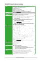
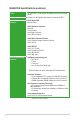
M4A88T-M specifications summary CPU AMD® Socket AM3 for AMD® Phenom™ II / Athlon™ II / Sempron™ 100 series processors Supports 45nm CPU Supports CPU up to 140W AMD® Cool ‘n’ Quiet™ Technology * Refer to www.asus.com for the AMD® CPU support list Chipset AMD® 880G / SB710 System Bus Up to 5200MT/s HyperTransport™ 3.0 interface Memory Dual-channel memory architecture 4 x 240-pin DIMM slots support maximum 16GB unbuffered ECC and non-ECC DDR3 1866(O.C.
M4A88T-M specifications summary USB 12 USB 2.0/1.1 ports (6 ports at midboard, 6 ports at the back panel) LAN Realtek® 8111E Gigabit LAN controller featuring AI NET 2 ASUS unique features ASUS Hybrid OS Express Gate ASUS Exclusive Features MemOK! Core Unlocker Anti-Surge Protection ASUS EPU-4 Engine ASUS Quiet Thermal Solution ASUS Fanless Design: Heatsink Solution ASUS Q-Fan ASUS EZ DIY ASUS O.C.
M4A88T-M specifications summary Back panel I/O ports 1 x PS/2 Combo port (Keyboard & Mouse) 1 x Optical S/PDIF Out port 1 x HDMI port 1 x DVI port 1 x D-Sub port 1 x LAN (RJ-45) port 6 x USB 2.0/1.1 ports 8-channel audio I/O ports Internal I/O connectors 3 x USB 2.0/1.1 connectors support additional 6 USB 2.0/1.
Chapter 1 Product introduction 1.1 Welcome! Thank you for buying an ASUS® M4A88T-M motherboard! The motherboard delivers a host of new features and latest technologies, making it another standout in the long line of ASUS quality motherboards! Before you start installing the motherboard, and hardware devices on it, check the items in your package with the list below. 1.2 Package contents Check your motherboard package for the following items.
AMD® 880G Chipset The AMD® 880G Chipset is designed to support up to 5200MT/s HyperTransport™ 3.0 (HT 3.0) interface speed and PCI Express 2.0 x16 graphics. It is optimized with AMD’s latest AM3 multi-core CPUs to provide excellent system performance and overclocking capabilities. HyperTransport™ 3.0 support HyperTransport™ 3.0 technology provides 2.6 times more bandwidth than HT1.0 that radically improves system efficiency for a smoother and faster computing environment.
Serial ATA 3Gb/s technology This motherboard supports hard drives based on the Serial ATA (SATA) 3Gb/s storage specifications, delivering enhanced salability and doubling the bus bandwidth for high-speed data saving and retrieval.
ASUS CrashFree BIOS 3 ASUS CrashFree BIOS 3 is an auto-recovery tool that allows you to restore a corrupted BIOS file using the bundled support DVD or a USB flash disk that contains the BIOS file. ASUS EZ Flash 2 ASUS EZ Flash 2 allows you to update the BIOS from a USB flash disk before entering the OS. ASUS EPU ASUS EPU is a unique power saving technology that detects the current system loadings and adjusts the power consumption in real time.
GPU NOS ASUS GPU NOS technology intelligently detects graphics loading and automatically boosts performance for the most demanding tasks. It provides you with a faster reaction time for an excellent graphics performance. ASUS MyLogo 2™ Turn your favorite photos into 256-color boot logos to personalize your system. ASUS Q-Fan ASUS Q-Fan technology intelligently adjusts CPU fan speeds according to system loading to ensure a quiet, cool, and efficient operation.
1.4 Before you proceed Take note of the following precautions before you install motherboard components or change any motherboard settings. • Unplug the power cord from the wall socket before touching any component. • Before handling components, use a grounded wrist strap or touch a safely grounded object or a metal object, such as the power supply case, to avoid damaging them due to static electricity. • Hold components by the edges to avoid touching the ICs on them.
1.5 Motherboard overview 1.5.1 Placement direction 1.5.2 Screw holes When installing the motherboard, ensure that you place it into the chassis in the correct orientation. The edge with external ports goes to the rear part of the chassis as indicated in the image below. Place eight screws into the holes indicated by circles to secure the motherboard to the chassis. DO NOT overtighten the screws! Doing so can damage the motherboard. Place this side towards the rear of the chassis.
1.5.3 Motherboard layout 1 2 3 1 4 5 24.4cm(9.6in) KB_USB56 ATX12V COM1 CPU_FAN 6 24.4cm(9.
1.6 Central Processing Unit (CPU) This motherboard comes with an AM3 socket designed for Phenom™ II / Athlon™ II / Sempron™ 100 series processors. The AM3 socket has a different pinout from the AM2+/AM2 socket. Ensure that you use a CPU designed for the AM3 socket. The CPU fits in only one correct orientation. DO NOT force the CPU into the socket to prevent bending the pins and damaging the CPU! 1.6.1 Installing the CPU To install a CPU: 1. Locate the CPU socket on the motherboard.
5. When the CPU is in place, push down the socket lever to secure the CPU. The lever clicks on the side tab to indicate that it is locked. 6. Install a CPU heatsink and fan following the instructions that comes with the heatsink package. You can also refer to section 1.6.2 Installing heatsink and fan for instructions. 7. Connect the CPU fan cable to the CPU_FAN connector on the motherboard.
1.6.2 Installing the heatsink and fan Ensure that you use only AMD-certified heatsink and fan assembly. To install the CPU heatsink and fan: 1. Place the heatsink on top of the installed CPU, ensuring that the heatsink fits properly on the retention module base. • The retention module base is already installed on the motherboard upon purchase. • You do not have to remove the retention module base when installing the CPU or installing other motherboard components.
3. Align the other end of the retention bracket to the retention module base. A clicking sound denotes that the retention bracket is in place. Ensure that the fan and heatsink assembly perfectly fits the retention mechanism module base, otherwise you cannot snap the retention bracket in place. 4. Push down the retention bracket lock on the retention mechanism to secure the heatsink and fan to the module base. 5.
1.7.2 Memory configurations You may install 512MB, 1GB, 2GB, and 4GB unbuffered ECC and non-ECC DDR3 DIMMs into the DIMM sockets. • You may install varying memory sizes in Channel A and Channel B. The system maps the total size of the lower-sized channel for the dual-channel configuration. Any excess memory from the higher-sized channel is then mapped for single-channel operation. • Always install DIMMs with the same CAS latency.
DDR3 1600 (O.C.) MHz capability DIMM support Vendor Part No. Size SS/ DS Chip Brand Chip NO. CL A-Data AD31600X002GMU 4096MB(Kit of 2) DS N/A Heat-Sink Package 7-7-7-20 • Corsair CM3X1G1600C9DHX 2048MB(Kit of 2) SS N/A Heat-Sink Package 9-9-9-24 CRUCIAL BL12864BA1608.8SFB(XMP) 3072MB(Kit of 3) SS N/A Heat-Sink Package 8-8-8-24 CRUCIAL BL12864BE2009.8SFB3(EPP) 3072MB(Kit of 3) SS N/A Heat-Sink Package Crucial BL25664TB1608.
DDR3 1333 MHz capability Vendor Part No. Size SS/ DS Chip Brand Chip NO.
DDR3 1066MHz capability Vendor Part No. Size SS/ DS Chip Brand Chip NO. CL Elpida EBJ51UD8BAFA-AC-E 512MB SS elpida J5308BASE-AC-E Elpida EBJ51UD8BAFA-AE-E 512MB SS elpida G.SKILL F3-8500CL6D-2GBHK 1024MB SS Kingston KVR1066D3N7/1G 1024MB Kingston KVR1066D3N7/1G Kingston DIMM support A* B* C* N/A • • • J5308BASE-AC-E N/A • • • G.
1.7.3 Installing a DIMM Unplug the power supply before adding or removing DIMMs or other system components. Failure to do so can cause severe damage to both the motherboard and the components. 2 1. Press the retaining clips outward to unlock a DIMM socket. 2. Align a DIMM on the socket such that the notch on the DIMM matches the break on the socket. DIMM notch 1 1 Unlocked retaining clip A DIMM is keyed with a notch so that it fits in only one direction.
1.8 Expansion slots In the future, you may need to install expansion cards. The following sub‑sections describe the slots and the expansion cards that they support. Unplug the power cord before adding or removing expansion cards. Failure to do so may cause you physical injury and damage motherboard components. 1.8.1 Installing an expansion card To install an expansion card: 1.
1.9 1. Jumpers Clear RTC RAM (CLRTC) This jumper allows you to clear the Real Time Clock (RTC) RAM in CMOS. You can clear the CMOS memory of date, time, and system setup parameters by erasing the CMOS RTC RAM data. The onboard button cell battery powers the RAM data in CMOS, which include system setup information such as system passwords. CLRTC 1 M4A88T-M 2 2 3 Normal (Default) Clear RTC M4A88T-M Clear RTC RAM To erase the RTC RAM: 1. Turn OFF the computer and unplug the power cord. 2.
1.10 Connectors 1.10.1 Rear panel ports 1 2 3 15 14 13 4 12 11 10 9 1. PS/2 keyboard / mouse combo port. This port is for a PS/2 keyboard or mouse. 2. Optical S/PDIF_OUT port. This port connects to an external audio output device via an optical S/PDIF cable. 3. VGA port. This 15-pin port is for a VGA monitor or other VGA-compatible devices. 4. LAN (RJ-45) port. This port allows Gigabit connection to a Local Area Network (LAN) through a network hub.
Refer to the audio configuration table below for the function of the audio ports in the 2, 4, 6, or 8-channel configuration.
Playback of Blu-ray discs • For better playback quality, we recommend that you follow the system requirements listed below.
1.10.2 1. Internal connectors ATX power connectors (24-pin EATXPWR, 4-pin ATX12V) These connectors are for an ATX power supply. The plugs from the power supply are designed to fit these connectors in only one orientation. Find the proper orientation and push down firmly until the connectors completely fit.
2. IDE connector (40-1 pin PRI_IDE) The onboard IDE connector is for Ultra DMA 133/100/66 signal cable. There are three connectors on each Ultra DMA 133/100/66 signal cable: blue, black, and gray.
3. Serial ATA connectors (7-pin SATA1-6) These connectors are for the Serial ATA signal cables for Serial ATA 3Gb/s hard disk and optical disk drives. The Serial ATA 3Gb/s is backward compatible with Serial ATA 1.5Gb/s specification. The data transfer rate of the Serial ATA 3Gb/s is faster than the standard parallel ATA with 133 MB/s (Ultra DMA133). If you install Serial ATA hard disk drives, you can create RAID 0, RAID 1, RAID 0+1, and JBOD configurations through the onboard SB710 chipset.
4. System panel connector (20-8 pin PANEL) This connector supports several chassis-mounted functions. +5V Ground Ground Speaker SPEAKER PLED- PLED+ PLED PANEL Reset Ground PWR Ground IDE_LED+ IDE_LED- PIN 1 M4A88T-M IDE_LED PWRSW RESET * Requires an ATX power supply M4A88T-M System panel connector • System power LED (2-pin PLED) This 2-pin connector is for the system power LED. Connect the chassis power LED cable to this connector.
5. USB connectors (10-1 pin USB78, USB910, USB1112) USB78 USB+5V USB_P12USB_P12+ GND NC USB910 USB1112 PIN 1 PIN 1 USB+5V USB_P9USB_P9+ GND USB+5V USB_P7USB_P7+ GND PIN 1 M4A88T-M USB+5V USB_P11USB_P11+ GND USB+5V USB_P8USB_P8+ GND NC USB+5V USB_P10USB_P10+ GND NC These connectors are for USB 2.0 ports. Connect the USB module cable to any of these connectors, then install the module to a slot opening at the back of the system chassis. These USB connectors comply with USB 2.
7. Digital audio connector (4-1 pin SPDIF_OUT) +5V SPDIFOUT GND This connector is for an additional Sony/Philips Digital Interface (S/PDIF) port. M4A88T-M SPDIF_OUT M4A88T-M Digital audio connector Ensure that the audio device of Sound playback is VIA High Definition Audio (the name may be different based on the OS). Go to Start > Control Panel > Sounds and Audio Devices > Sound Playback to configure the setting. The S/PDIF module is purchased separately. 8.
9. CPU and chassis fan connectors (4-pin CPU_FAN and 3-pin CHA_FAN) The fan connectors support cooling fans of 350mA~740mA (8.88W max.) or a total of 1A~2.22A (26.64W max.) at +12V. Connect the fan cables to the fan connectors on the motherboard, ensuring that the black wire of each cable matches the ground pin of the connector. GND CPU FAN PWR CPU FAN IN CPU FAN PWM CPU_FAN CHA_FAN M4A88T-M fan connectors Rotation +12V GND M4A88T-M DO NOT forget to connect the fan cables to the fan connectors.
1.11 Onboard switch Onboard switches allow you to fine-tune performance when working on a bare or open-case system. This is ideal for overclockers and gamers who continually change settings to enhance system performance. 1. MemOK! switch Installing DIMMs that are incompaible with the motherboard may cause system boot failure, and the DRAM_LED near the MemOK! switch lights continuously.
1.12 1. Onboard LED Standby Power LED The motherboard comes with a standby power LED that lights up to indicate that the system is ON, in sleep mode, or in soft-off mode. This is a reminder that you should shut down the system and unplug the power cable before removing or plugging in any motherboard component. The illustration below shows the location of the onboard LED. SB_PWR M4A88T-M OFF ON Standby Power Powered Off M4A88T-M Onboard Power LED 2.
1.13 Software support 1.13.1 Installing an operating system This motherboard supports Windows® XP/Vista Operating Systems (OS). Always install the latest OS version and corresponding updates to maximize the features of your hardware. • Motherboard settings and hardware options vary. Refer to your OS documentation for detailed information.
Chapter 2 BIOS information 2.1 Managing and updating your BIOS Save a copy of the original motherboard BIOS file to a USB flash disk in case you need to restore the BIOS in the future. Copy the original motherboard BIOS using the ASUS Update utility. 2.1.1 ASUS Update The ASUS Update is a utility that allows you to manage, save, and update the motherboard BIOS in Windows® environment. • ASUS Update requires an Internet connection either through a network or an Internet Service Provider (ISP).
The ASUS Update utility is capable of updating itself through the Internet. Always update the utility to avail all its features. Updating from a BIOS file 3. a. Select Update BIOS from a file, then click Next. b. Locate the BIOS file from the Open window, then click Open. Follow the onscreen instructions to complete the updating process. 2.1.2 ASUS EZ Flash 2 The ASUS EZ Flash 2 feature allows you to update the BIOS without using an OS‑based utility.
• This function supports USB flash disks with FAT 32/16 format and single partition only. • DO NOT shut down or reset the system while updating the BIOS to prevent system boot failure! 2.1.3 ASUS CrashFree BIOS 3 ASUS CrashFree BIOS 3 is an auto recovery tool that allows you to restore the BIOS file when it fails or gets corrupted during the updating process. You can restore a corrupted BIOS file using the motherboard support DVD or a USB flash drive that contains the BIOS file.
2.2 BIOS setup program This motherboard supports a programmable Serial Peripheral Interface (SPI) chip that you can update using the provided utility described in section 2.1 Managing and updating your BIOS. Use the BIOS Setup program when you are installing a motherboard, reconfiguring your system, or prompted to “Run Setup.” This section explains how to configure your system using this utility.
2.2.1 BIOS menu screen Menu items Main Menu bar Advanced Configuration fields Power Main Settings System Time System Date Primary IDE Master Primary IDE Slave SATA1 SATA2 SATA3 SATA4 SATA5 SATA6 SATA Configuration General help BIOS SETUP UTILITY Boot Tools Exit [19:34:30] [Thu 01/10/2002] :[Not :[Not :[Not :[Not :[Not :[Not :[Not :[Not Detected] Detected] Detected] Detected] Detected] Detected] Detected] Detected] System Information Use [ENTER], [TAB] or [SHIFT-TAB] to select a field.
2.2.4 Menu items 2.2.5 Submenu items 2.2.6 Configuration fields 2.2.7 Pop-up window The highlighted item on the menu bar displays the specific items for that menu. For example, selecting Main shows the Main menu items. The other items (Advanced, Power, Boot, Tools, and Exit) on the menu bar have their respective menu items. A solid triangle before each item on a menu screen means that the item has a submenu. To display the submenu, select the item and press .
2.3 Main menu When you enter the BIOS Setup program, the Main menu screen appears, giving you an overview of the basic system information. Refer to section 2.2.1 BIOS menu screen for information on the menu screen items and how to navigate through them.
LBA/Large Mode [Auto] Enables or disables the LBA mode. Setting this item to [Auto] enables the LBA mode if the device supports this mode, and if the device was not previously formatted with LBA mode disabled. Configuration options: [Disabled] [Auto] Block (Multi-Sector Transfer) M [Auto] Enables or disables data multi-sectors transfers. When this item is set to [Auto], the data transfer from and to the device occurs multiple sectors at a time if the device supports multisector transfer feature.
2.3.5 System Information This menu gives you an overview of the general system specifications. The BIOS automatically detects the items in this menu. BIOS Information Displays the auto-detected BIOS information. Processor Displays the auto-detected CPU specification. System Memory Displays the auto-detected system memory. 2.4 Advanced menu The Advanced menu items allow you to change the settings for the CPU and other system devices. Take caution when changing the settings of the Advanced menu items.
The following item only appears when you set CPU Overclocking to [Manual]. CPU/HT Reference Clock (MHz) [200] Sets the CPU/HT Reference Clock. Configuration options: [Min.=200] [Max.=550] The following item only appears when you set CPU Overclocking to [Overclock Profile]. Overclock Options [Auto] Selects the overclocking profile. Configuration options: [Auto] [Overclock 2%] [Overclock 5%] [Overclock 8%] [Overclock 10%] GPU Engine Clock [700] Sets the GPU Engine Clock. Configuration options: [Min.
HT Link Frequency [Auto] Sets the HyperTransport link speed. Configuration options: [200MHz] [400MHz] [600MHz] ~ [2000MHz] [Auto] HT Link Width [Auto] Sets the HyperTransport link width. Configuration options: [Auto] [8 Bit] [16 Bit] HT Over Voltage [Auto] Sets the HT over voltage. The value ranges from 1.20000V to 1.40000V with a 0.01000V increment. Key in the value directly or use +/- to adjust the voltage. DRAM Frequency [Auto] Sets the DRAM frequency.
Memory Over Voltage [Auto] Sets the memory over voltage. The value ranges from 1.2000V to 2.445V with a 0.0150V increment. Use the <+> / <-> keys to adjust the value. Chipset Over Voltage [Auto] Sets the chipset over voltage. The values range from 1.10000V to 1.73000V with a 0.01000V increment. Use the <+> / <-> keys to adjust the value. 2.4.2 CPU Configuration The items in this menu show the CPU-related information that the BIOS automatically detects.
2.4.3 Chipset NorthBridge Configuration Memory Configuration Bank Interleaving [Auto] Allows you to enable the bank memory interleaving. Configuration options: [Disabled] [Auto] Channel Interleaving [XOR of Address bits [20:16, 6]] Allows you to enable the channel memory interleaving.
Surround View [Auto] This item is not user-configurable. This item becomes user-configurable when you install an ATI graphics card into the PCIe x16 slot. Frame Buffer Location [Above 4G] Configuration options: [Below 4G] [Above 4G] AMD 880 HDMI Audio [Enabled] Enables or disables AMD 880 HD audio. Configuration options: [Enabled] [Disabled] 2.4.4 Onboard Device Configuration Serial Port1 Address [3F8/IRQ4] Selects the Serial Port1 base address.
2.4.5 PCIPnP The PCI PnP menu items allow you to change the advanced settings for PCI/PnP devices. The menu includes setting IRQ and DMA channel resources for either PCI/PnP or legacy ISA devices and setting the memory size block for legacy ISA devices. Take caution when changing the settings of the PCI PnP menu items. Incorrect field values can cause the system to malfunction. Plug And Play O/S [No] When this item is set to [No], BIOS configures all the devices in the system.
2.5 Power menu The Power menu items allow you to change the settings for the Advanced Configuration and Power Interface (ACPI) and the Advanced Power Management (APM). Select an item then press to display the configuration options. Main Advanced Power BIOS SETUP UTILITY Boot Tools Exit Power Settings Suspend Mode ACPI 2.0 Support ACPI APIC support [Auto] [Enabled] [Enabled] Select the ACPI state used for System Suspend.
Power on From S5 By PS/2 Keyboard [Disabled] Enables or disables PS/2 keyboard to generate a wake event. Configuration options: [Disabled] [Space Bar] [Power Key] [Ctrl-Esc] Power on From S5 By RTC Alarm [Disabled] Enables or disables RTC to generate a wake event. Configuration options: [Disabled] [Enabled] 2.5.5 HW Monitor Configuration CPU/MB Temperature [xxxºC/xxxºF] or [Ignored] The onboard hardware monitor automatically detects and displays the motherboard and CPU temperatures.
2.6 Boot menu The Boot menu items allow you to change the system boot options. Select an item then press to display the sub-menu. Main Advanced Power BIOS SETUP UTILITY Boot Tools Exit Boot Settings Boot Device Priority Boot Settings Configuration Security Specifies the Boot Device Priority sequence. A virtual floppy disk drive (Floppy Drive B:) may appear when you set the CD-ROM drive as the first boot device.
AddOn ROM Display Mode [Force BIOS] Sets the display mode for option ROM. Configuration options: [Force BIOS] [Keep Current] Bootup Num-Lock [On] Selects the power-on state for the NumLock. Configuration options: [Off] [On] Wait for ‘F1’ If Error [Enabled] When this item is set to [Enabled], the system waits for the F1 key to be pressed when error occurs.
Change User Password Select this item to set or change the user password. The User Password item on top of the screen shows the default Not Installed. After you set a password, this item shows Installed. To set a User Password: 1. Select the Change User Password item and press . 2. In the password box, key in a password containing up to six letters or numbers, or both, then press . 3. Confirm the password when prompted.
2.7.2 Express Gate [Auto] Enables or disables the ASUS Express Gate feature. ASUS Express Gate is a unique instant-on environment that provides quick access to the Internet and Skype. Configuration options: [Enabled] [Disabled] [Auto] Enter OS Timer [10 Seconds] Sets countdown duration that the system waits at the Express Gate’s first screen before starting Windows or other installed OS. Choose [Prompt User] to stay at the first screen of Express Gate for user action.
Start O.C. Profile Allows you to run the utility to save and load CMOS. Press to run the utility. ASUSTek O.C. Profile Utility V2.12 Current CMOS BOARD: M4A88T-M VER: 0303 (H:00 B:06) DATE: 02/08/2010 Restore CMOS BOARD: Unknown VER: Unknown DATE: Unknown PATH: A:\ A: Note [Enter] Select or Load [Up/Down/Home/End] Move [Tab] Switch [B] Backup [V] Drive Info [Esc] Exit • This function can support devices such as a USB flash disk with FAT 32/16 format and single partition only.
2.8 Exit menu The Exit menu items allow you to load the optimal or failsafe default values for the BIOS items, and save or discard your changes to the BIOS items. Main Advanced Power Exit Options Exit & Save Changes Exit & Discard Changes Discard Changes Load Setup Defaults BIOS SETUP UTILITY Boot Tools Exit Exitsystem systemsetup setup Exit aftersaving savingthe the after changes. changes. F10key keycan canbe beused used F10 forthis thisoperation. operation.
ASUS contact information ASUSTeK Computer Inc. Address Telephone Fax E-mail Web site Technical Support Telephone Online support 15 Li-Te Road, Peitou, Taipei, Taiwan 11259 +886-2-2894-3447 +886-2-2890-7798 info@asus.com.tw www.asus.com.tw +86-21-38429911 support.asus.com ASUS Computer International (America) Address Telephone 800 Corporate Way, Fremont, CA 94539, USA +1-510-739-3777 Fax Web site +1-510-608-4555 usa.asus.
(510)739-3777/(510)608-4555 800 Corporate Way, Fremont, CA 94539. Asus Computer International Signature : Date : Representative Personʼs Name : Apr. 24, 2010 Steve Chang / President This device complies with part 15 of the FCC Rules. Operation is subject to the following two conditions: (1) This device may not cause harmful interference, and (2) this device must accept any interference received, including interference that may cause undesired operation.