Motherboard M4N78-AM
E4379 First Edition V1 March 2009 Copyright © 2009 ASUSTeK Computer Inc. All Rights Reserved. No part of this manual, including the products and software described in it, may be reproduced, transmitted, transcribed, stored in a retrieval system, or translated into any language in any form or by any means, except documentation kept by the purchaser for backup purposes, without the express written permission of ASUSTeK Computer Inc. (“ASUS”).
Contents Notices........................................................................................................... v Safety information....................................................................................... vi About this guide.......................................................................................... vi M4N78-AM specifications summary........................................................ viii Chapter 1: Product introduction 1.1 Before you proceed..................
Contents 2.4 2.5 2.6 2.7 2.8 iv 2.3.4 Storage Configuration...................................................... 2-6 2.3.5 System Information.......................................................... 2-6 Advanced menu............................................................................ 2-6 2.4.1 JumperFree Configuration............................................... 2-7 2.4.2 CPU Configuration........................................................... 2-9 2.4.3 Chipset...............
Notices Federal Communications Commission Statement This device complies with Part 15 of the FCC Rules. Operation is subject to the following two conditions: • This device may not cause harmful interference, and • This device must accept any interference received including interference that may cause undesired operation. This equipment has been tested and found to comply with the limits for a Class B digital device, pursuant to Part 15 of the FCC Rules.
Safety information Electrical safety • To prevent electric shock hazard, disconnect the power cable from the electric outlet before relocating the system. • When adding or removing devices to or from the system, ensure that the power cables for the devices are unplugged before the signal cables are connected. If possible, disconnect all power cables from the existing system before you add a device.
Conventions used in this guide To ensure that you perform certain tasks properly, take note of the following symbols used throughout this manual. DANGER/WARNING: Information to prevent injury to yourself when trying to complete a task. CAUTION: Information to prevent damage to the components when trying to complete a task. IMPORTANT: Instructions that you MUST follow to complete a task. NOTE: Tips and additional information to help you complete a task.
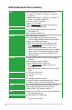
M4N78-AM specifications summary CPU AMD® Socket AM2+ / AM2 for AMD® Phenom™ x4 / Phenom™ x3 / Athlon™ x2 / Athlon™ / Sempron™ processors Compatible with Phenom™ II / Athlon™ x4 / Athlon™ x3 / Athlon™ x2 processors (AM3 CPU) AMD Cool ‘n’ Quiet™ Technology Supports CPU up to 95W Refer to www.asus.com for the AMD CPU support list Chipset NVIDIA® GeForce 8200 (MCP78S) System bus Up to 5200 MT/s HyperTransport™ 3.
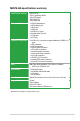
M4N78-AM specifications summary ASUS special features ASUS Q-Fan ASUS CrashFree BIOS3 ASUS EZ Flash2 ASUS AI NET2 ASUS MyLogo2 Back panel I/O ports 1 x PS/2 Keyboard port 1 x PS/2 Mouse port 1 x RJ45 port 1 x VGA port 4 x USB 2.0/1.1 ports 6-channel audio I/O ports 1 x COM port 1 x LPT port Internal I/O connectors 3 x USB 2.0/1.1 connectors support additional 6 USB 2.0/1.
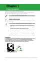
Chapter 1 Product introduction Thank you for buying an ASUS® M4N78-AM motherboard! Before you start installing the motherboard, and hardware devices on it, check the items in your motherboard package. Refer to page ix for the list of accessories. If any of the items is damaged or missing, contact your retailer. 1.1 Before you proceed Take note of the following precautions before you install motherboard components or change any motherboard settings.
1.2 Motherboard overview 1.2.1 Motherboard layout SOCKET AM2+ COM1 Ensure that you install the motherboard into the chassis in the correct orientation. The edge with external ports goes to the rear part of the chassis. Place this side towards the rear of the chassis. USBPW1-4 NVIDIA® GeForce 8200 B5071A 2KFBG USBPW5-10 VIA VT1708S Place six screws into the holes indicated by circles to secure the motherboard to the chassis. DO NOT overtighten the screws! Doing so can damage the motherboard. 1.
1.3 Central Processing Unit (CPU) This motherboard comes with an AM2+ / AM2 socket designed for AMD® Phenom™ x4 / Phenom™ x3 / Athlon™ x2 / Athlon™ / Sempron™ processors. It also supports AM3 CPUs including Phenom™ II / Athlon™ x4 / Athlon™ x3 / Athlon™ x2 processors. The AM2+ / AM2 socket has a different pinout from the 940-pin socket designed for the AMD Opteron™ processor. Use a CPU that is designed for the AM2+ socket. 1.4 System memory 1.4.
• Due to the memory address limitation on 32-bit Windows® OS, when you install 4GB or more memory on the motherboard, the actual usable memory for the OS can be about 3GB or less. For effective use of memory, we recommend that you do any of the following: - Install a maximum of 3GB system memory if you are using a 32-bit Windows® OS. Use a 64-bit Windows® OS if you want to install 4GB or more memory on the motherboard.
DDR2-800MHz capability DIMM support A* B* Vendor Part No. Size SS/ DS Chip No. CL Chip Brand Crucial BL12864AL804.8FE5 SS Heat-Sink Package 4 N/A • • M2Y1G64TU88D5B-AC 0828.GS M2Y1G64TU8HB0B-25C M2Y2G64TU8HD5B-AC 0826.
DDR2-667MHz capability DIMM support A* B* • • • • • • • • • • • • • • • • • • • • • • Vendor Part No. Size SS/ DS Chip No. CL Chip Brand ADATA ADATA Apacer Apacer Corsair G.SKILL G.SKILL GEIL GEIL HY Kingmax M2OAD5G314170Q1C58 M2OAD5H3J4170I1C53 78.01G9O.9K5 78.A1G9O.
1.6 1. Jumpers Clear RTC RAM (3-pin CLRTC) This jumper allows you to clear the Real Time Clock (RTC) RAM in CMOS. You can clear the CMOS memory of date, time, and system setup parameters by erasing the CMOS RTC RAM data. The onboard button cell battery powers the RAM data in CMOS, which include system setup information such as system passwords. To erase the RTC RAM: 1. Turn OFF the computer and unplug the power cord. 2. Move the jumper cap from pins 1-2 (default) to pins 2-3.
3. Keyboard power (3-pin KBPWR) This jumper allows you to enable or disable the keyboard wake-up feature. When you set this jumper to pins 2-3 (+5VSB), you can wake up the computer by pressing a key on the keyboard (the default is the Space Bar). This feature requires an ATX power supply that can supply at least 1A on the +5VSB lead, and a corresponding setting in the BIOS. 1.7 Connectors 1.7.1 Rear panel ports 1 2 11 10 3 9 8 7 4 5 6 1. PS/2 Mouse port (green).
4. Line In port (light blue). This port connects to the tape, CD, DVD player, or other audio sources. 5. Line Out port (lime). This port connects to a headphone or a speaker. In 4-channel and 6-channel configurations, the function of this port becomes Front Speaker Out. 6. Microphone port (pink). This port connects to a microphone. Refer to the audio configuration table below for the function of the audio ports in 2, 4, or 6-channel configuration.
2. Serial ATA connectors (7-pin SATA1, SATA2, SATA3, SATA4) These connectors are for the Serial ATA signal cables for Serial ATA 3Gb/s hard disk and optical disk drives. The Serial ATA 3Gb/s is backward compatible with Serial ATA 1.5Gb/s specification. The data transfer rate of the Serial ATA 3Gb/s is faster than that of the standard parallel ATA (133MB/s). Install the Windows® XP Service Pack 1 before using Serial ATA. 3.
4. IDE connector (40-1 pin PRI_IDE) The onboard IDE connector is for an Ultra DMA 133/100/66 signal cable. There are three connectors on each Ultra DMA 133/100/66 signal cable: blue, black, and gray. Connect the blue connector to the motherboard’s IDE connector, then select one of the following modes to configure your devices.
6. USB connectors (10-1 pin USB56, USB78, USB910) These connectors are for USB 2.0 ports. Connect the USB module cable to any of these connectors, then install the module to a slot opening at the back of the system chassis. These USB connectors comply with the USB 2.0 specification that supports up to 480Mbps connection speed. Never connect a 1394 cable to the USB connectors. Doing so will damage the motherboard! The USB 2.0 module is purchased separately. 7.
8. ATX power connectors (24-pin EATXPWR, 4-pin ATX12V) These connectors are for an ATX power supply. The plugs from the power supply are designed to fit these connectors in only one orientation. Find the proper orientation and push down firmly until the connectors completely fit. • We recommend that you use an ATX 12V Specification 2.0‑compliant power supply unit (PSU) with a minimum of 300W power rating. This PSU type has 24-pin and 4-pin power plugs.
• System power LED (2-pin PWRLED) • This 2-pin connector is for the system power LED. Connect the chassis power LED cable to this connector. The system power LED lights up when you turn on the system power, and blinks when the system is in sleep mode. Hard disk drive activity LED (2-pin HDLED) • This 2-pin connector is for the HDD Activity LED. Connect the HDD Activity LED cable to this connector. The IDE LED lights up or flashes when data is read from or written to the HDD.
1.8 Software support 1.8.1 Installing an operating system This motherboard supports Windows® XP/Vista Operating Systems (OS). Always install the latest OS version and corresponding updates to maximize the features of your hardware. • Motherboard settings and hardware options vary. Refer to your OS documentation for detailed information.
Chapter 2 BIOS information 2.1 Managing and updating your BIOS Save a copy of the original motherboard BIOS file to a USB flash disk in case you need to restore the BIOS in the future. Copy the original motherboard BIOS using the ASUS Update utility. 2.1.1 ASUS Update utility The ASUS Update is a utility that allows you to manage, save, and update the motherboard BIOS in Windows® environment. • ASUS Update requires an Internet connection either through a network or an Internet Service Provider (ISP).
Updating from a BIOS file a. Select Update BIOS from a file, then click Next. b. Locate the BIOS file from the Open window, then click Open. 3. Follow the onscreen instructions to complete the updating process. 2.1.2 ASUS EZ Flash 2 utility The ASUS EZ Flash 2 feature allows you to update the BIOS without using an OS‑based utility. Download the latest BIOS file from the ASUS website at www.asus.com. To update the BIOS using EZ Flash 2: 1.
2.1.3 ASUS CrashFree BIOS 3 utility The ASUS CrashFree BIOS 3 is an auto recovery tool that allows you to restore the BIOS file when it fails or gets corrupted during the updating process. You can update a corrupted BIOS file using the motherboard Support DVD or a USB flash disk that contains the updated BIOS file. • Prepare the motherboard Support DVD or a USB flash disk containing the updated motherboard BIOS before using this utility.
2.2 BIOS setup program Use the BIOS Setup program when you are installing a motherboard, reconfiguring your system, or prompted to “Run Setup.” This section explains how to configure your system using this utility. If you want to enter Setup after POST, reboot the system by doing any of the following procedures: • Restart using the OS standard shut-down procedure. • Press ++ simultaneously. • Press the reset button on the system chassis.
2.3.3 Primary IDE Master/Slave, SATA 1/2/3/4 While entering Setup, the BIOS automatically detects the presence of IDE/SATA devices. There is a separate submenu for each IDE/SATA device. Select a device item then press to display the IDE/SATA device information. The BIOS automatically detects the values opposite the dimmed items (Device, Vendor, Size, LBA Mode, Block Mode, PIO Mode, Async DMA, Ultra DMA, and SMART monitoring). These values are not user-configurable.
2.3.4 Storage Configuration The items in this menu allow you to set or change the configurations for the storage devices installed in the system. Select an item then press if you want to configure the item. Onboard PCI IDE Controller [Enabled] Enables or disables the onboard IDE controller. Configuration options: [Disabled] [Enabled] OnChip S-ATA Controller [Enabled] Enables or disables the onchip SATA controller.
2.4.1 JumperFree Configuration The items in this menu may vary depending on the AMD CPU type. CPU Overclocking [Auto] Selects the CPU overclocking options to achieve desired CPU internal frequency. [Manual] - Allows you to manually set overclocking parameters. [Auto] - Loads the optimal settings for the system. [Overclock Profile] - Loads overclocking profiles with optimal parameters for stability when overclocking. The following item appears only when the CPU Overclocking item is set to [Manual].
Processor Frequency Multiplier [Auto] Allows you to select the processor frequency. Configuration options: [Auto] [x4.0 800MHz] [x5.0 1000MHz] [x6.0 1200MHz] [x7.0 1400MHz] [x8.0 1600MHz] [x9.0 1800MHz] Processor Voltage [Standard] Allows you to set the processor voltage. Configuration options: [Power Saving Mode] [Standard] [+50mv] [+100mv] Hyper Transport Speed [Auto] Allows you to select the Hyper Transport speed.
tWRRD [Auto] Configuration options: [Auto] [0 CLK] ~ [3 CLK] tWTR [Auto] Configuration options: [Auto] [1 CLK] [2 CLK] [3 CLK] tWRWR [Auto] Configuration options: [Auto] [1 CLK] [2 CLK] [3 CLK] tRDRD [Auto] Configuration options: [Auto] [2 CLK] [3 CLK] [4 CLK] [5 CLK] tRFC0/1/2/3 [Auto] Configuration options: [Auto] [75ns] [105ns] [127.5ns] [195ns] [327.5ns] Memory Over Voltage [Auto] Allows you to set the memory over voltage. The value ranges from 1.85000V to 2.24375V with a 0.00625V increment.
2.4.3 Chipset The Chipset menu allows you to change the advanced chipset settings. Select an item then press to display the sub-menu. NorthBridge Configuration Memory Configuration Bank Interleaving [Auto] Allows you to enable the bank memory interleaving. Configuration options: [Disabled] [Auto] Channel Interleaving [Disabled] Allows you to enable the channel memory interleaving.
PCIE 2.0 Support [Auto] Configures the PCIE 2.0 support. Configuration options: [Disabled] [Auto] AZALIA AUDIO [Enabled] Allows you to enable or disable the HD audio mode. Configuration options: [Disabled] [Enabled] Front Panel Select [HD Audio] Allows you to set the HD audio mode. Configuration options: [AC97] [HD Audio] Onboard LAN [Enabled] Allows you to set or disable the Onboard LAN.
2.4.6 USB Configuration The items in this menu allows you to change the USB-related features. Select an item then press to display the configuration options. The Module Version and USB Devices Enabled items show the auto-detected values. If no USB device is detected, the item shows None. USB Functions [Enabled] Enables or disables the USB functions. Configuration options: [Enabled] [Disabled] USB 2.0 Controller [Enabled] Enables or disables the USB 2.0 Controller.
2.5.1 Suspend Mode [Auto] 2.5.2 ACPI 2.0 Support [Disabled] 2.5.3 ACPI APIC Support [Enabled] 2.5.4 APM Configuration Allows you to select the Advanced Configuration and Power Interface (ACPI) state to be used for system suspend. Configuration options: [S1 (POS) Only] [S3 Only] [Auto] [S1(POS) Only] - Enables the system to enter the ACPI S1 (Power on Suspend) sleep state In S1 sleep state, the system appears suspended and stays in a low power mode. The system can be resumed at any time.
2.5.5 Hardware Monitor CPU Temperature [xxxºC/xxxºF] MB Temperature [xxxºC/xxxºF] The onboard hardware monitor automatically detects and displays the motherboard and CPU temperatures. Select Ignored if you do not want to display the detected temperatures. CPU Fan Speed [xxxxRPM] or [Ignored] The onboard hardware monitor automatically detects and displays the CPU fan speed in rotations per minute (RPM). If the fan is not connected to the motherboard, the field shows N/A.
AddOn ROM Display Mode [Force BIOS] Sets the display mode for option ROM. Configuration options: [Force BIOS] [Keep Current] Bootup Num-Lock [On] Allows you to select the power-on state for the NumLock. Configuration options: [Off] [On] Wait for ‘F1’ If Error [Enabled] When set to Enabled, the system waits for the F1 key to be pressed when error occurs.
Change User Password Select this item to set or change the user password. The User Password item on top of the screen shows the default Not Installed. After you set a password, this item shows Installed. To set a User Password: 1. Select the Change User Password item. 2. From the password box, key in a password composed of up to six letters and/or numbers, then press . 3. Confirm the password when prompted. The message Password Installed appears after you set your password successfully.