• M5A78L-M LX V2 • M5A78L-M LX PLUS Motherboard M5A78L-M LX Series
E6816 First Edition (V1) August 2011 Copyright © 2011 ASUSTeK Computer Inc. All Rights Reserved. No part of this manual, including the products and software described in it, may be reproduced, transmitted, transcribed, stored in a retrieval system, or translated into any language in any form or by any means, except documentation kept by the purchaser for backup purposes, without the express written permission of ASUSTeK Computer Inc. (“ASUS”).
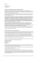
Contents Notices.......................................................................................................... vi Safety information...................................................................................... vii About this guide........................................................................................ viii M5A78L-M LX Series specifications summary......................................... ix Chapter 1: Product introduction 1.1 Welcome!...................................
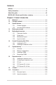
Contents 1.11 Software support......................................................................... 1-27 1.11.1 1.11.2 Installing an operating system....................................... 1-27 Support DVD information............................................... 1-27 Chapter 2: BIOS information 2.1 Managing and updating your BIOS............................................. 2-1 2.1.1 ASUS Update utility......................................................... 2-1 2.1.3 ASUS CrashFree BIOS 3....
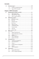
Contents 2.5.3 ACPI APIC Support [Enabled]........................................ 2-17 2.5.5 HW Monitor Configuration.............................................. 2-18 2.5.4 2.6 2.5.6 2.8 Anti Surge Support [Enabled]........................................ 2-18 Boot menu................................................................................... 2-19 2.6.1 Boot Device Priority....................................................... 2-19 2.6.3 Security.....................................
Notices Federal Communications Commission Statement This device complies with Part 15 of the FCC Rules. Operation is subject to the following two conditions: • This device may not cause harmful interference, and • This device must accept any interference received including interference that may cause undesired operation. This equipment has been tested and found to comply with the limits for a Class B digital device, pursuant to Part 15 of the FCC Rules.
REACH Complying with the REACH (Registration, Evaluation, Authorisation, and Restriction of Chemicals) regulatory framework, we published the chemical substances in our products at ASUS REACH website at http://csr.asus.com/english/REACH.htm. DO NOT throw the motherboard in municipal waste. This product has been designed to enable proper reuse of parts and recycling.
About this guide This user guide contains the information you need when installing and configuring the motherboard. How this guide is organized This guide contains the following parts: • Chapter 1: Product introduction • This chapter describes the features of the motherboard and the new technology it supports. Chapter 2: BIOS information This chapter tells how to change system settings through the BIOS Setup menus. Detailed descriptions of the BIOS parameters are also provided.
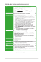
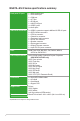
M5A78L-M LX Series specifications summary CPU AMD® Socket AM3+ for AMD® FX™ / Phenom™ II / Athlon™ II / Sempron™ 100 series processors AMD® Cool ‘n’ Quiet™ Technology Supports CPU up to 125W * Refer to www.asus.com for the AMD® CPU support list Chipset AMD® 760G(780L) / SB710 Front side bus Up to 5200 MT/s HyperTransport™ 3.0 interface Memory Dual-channel memory architecture 2 x 240-pin DIMM slots support maximum 8GB unbuffered ECC and non-ECC DDR3 1866(O.C.) / 1600(O.C.
M5A78L-M LX Series specifications summary Back panel I/O ports 1 x PS/2 Keyboard port 1 x PS/2 Mouse port 1 x COM port 1 x LPT port 1 x D-Sub port 1 x LAN (RJ-45) port 4 x USB 2.0 ports 3 x Audio jacks Internal I/O connectors 3 x USB 2.0 connectors support additional 6 USB 2.0 ports 6 x SATA 3.
Chapter 1 Product introduction 1.1 Welcome! Thank you for buying an ASUS® M5A78L-M LX Series motherboard! The motherboard delivers a host of new features and latest technologies, making it another standout in the long line of ASUS quality motherboards! Before you start installing the motherboard, and hardware devices on it, check the items in your package with the list below. 1.2 Package contents Check your motherboard package for the following items.
HyperTransport™ 3.0 support HyperTransport™ 3.0 technology provides 2.6 times more bandwidth than HT1.0 that radically improves system efficiency for a smoother and faster computing environment. AMD® Cool ‘n’ Quiet Technology This motherboard supports the AMD® Cool ‘n’ Quiet technology which monitors system operation and automatically adjusts CPU voltage and frequency for a cool and quiet operating environment. Dual-Channel DDR3 1866 (O.C.
1.3.2 1 2 Innovative ASUS features Core Unlocker ASUS Core Unlocker simplifies the activation of a latent AMD® CPUwith just pressing a key. Enjoy an instant performance boost by simply unlocking the extra cores, without performing complicated BIOS changes. ASUS Turbo Key ASUS Turbo Key allows you to turn the PC power button into an overclocking button. After the easy setup, Turbo Key boosts performances without interrupting ongoing work or games, simply through pressing the button.
ErP ready The motherboard is European Union´s Energy-related Products (ErP) ready, and ErP requires products to meet certain energy efficiency requirements in regards to energy consumptions. This is in line with ASUS vision of creating environment-friendly and energy-efficient products through product design and innovation to reduce carbon footprint of the product and thus mitigate environmental impacts.
1.4 Before you proceed Take note of the following precautions before you install motherboard components or change any motherboard settings. • Unplug the power cord from the wall socket before touching any component. • Before handling components, use a grounded wrist strap or touch a safely grounded object or a metal object, such as the power supply case, to avoid damaging them due to static electricity. • Hold components by the edges to avoid touching the ICs on them.
1.5 Motherboard overview 1.5.1 Placement direction 1.5.2 Screw holes When installing the motherboard, ensure that you place it into the chassis in the correct orientation. The edge with external ports goes to the rear part of the chassis as indicated in the image below. Place six screws into the holes indicated by circles to secure the motherboard to the chassis. DO NOT overtighten the screws! Doing so can damage the motherboard. Place this side towards the rear of the chassis.
1.5.3 Motherboard layout 1 2 3 5 4 6 20.3cm(8.0in) KBMS KBPWR EPU EATXPWR LAN1_USB12 ICS 9LPRS483 CPU_FAN AMD® 760G SATA3G_5 CHA_FAN PCIEX1_1 RTL 8111E SATA3G_6 AUDIO 3 24.4cm(9.
1.6 Central Processing Unit (CPU) This motherboard comes with an AM3+ socket designed for FX™ / Phenom™ II / Athlon™ II / Sempron™ 100 series processors. The AM3+ socket has a different pinout from the AM2+/AM2 socket. Ensure that you use a CPU designed for the AM3+ socket. The CPU fits in only one correct orientation. DO NOT force the CPU into the socket to prevent bending the pins and damaging the CPU! 1.6.1 Installing the CPU To install a CPU: 1. Locate the CPU socket on the motherboard.
5. When the CPU is in place, push down the socket lever to secure the CPU. The lever clicks on the side tab to indicate that it is locked. 6. Install a CPU heatsink and fan following the instructions that comes with the heatsink package. You can also refer to section 1.6.2 Installing heatsink and fan for instructions. 7. Connect the CPU fan cable to the CPU_FAN connector on the motherboard.
1.6.2 Installing the heatsink and fan Ensure that you use only AMD-certified heatsink and fan assembly. To install the CPU heatsink and fan: 1. Place the heatsink on top of the installed CPU, ensuring that the heatsink fits properly on the retention module base. • The retention module base is already installed on the motherboard upon purchase. • You do not have to remove the retention module base when installing the CPU or installing other motherboard components.
3. Align the other end of the retention bracket to the retention module base. A clicking sound denotes that the retention bracket is in place. Ensure that the fan and heatsink assembly perfectly fits the retention mechanism module base, otherwise you cannot snap the retention bracket in place. 4. Push down the retention bracket lock on the retention mechanism to secure the heatsink and fan to the module base. 5.
1.7.2 Memory configurations You may install 1GB, 2GB, and 4GB unbuffered ECC and non-ECC DDR3 DIMMs into the DIMM sockets. • You may install varying memory sizes in Channel A and Channel B. The system maps the total size of the lower-sized channel for the dual-channel configuration. Any excess memory from the higher-sized channel is then mapped for single-channel operation. • Always install DIMMs with the same CAS latency.
DDR3-1600(O.C.) MHz capability Part No. Size SS/ DS G.SKILL F3-12800CL9D-2GBNQ 2048MB(Kit of 2) SS N/A Heat-Sink Package 9-9-9-24 1.5V~1.6V • • G.SKILL F3-12800CL8T-6GBHK 2048MB DS N/A Heat-Sink Package 8-8-8-21 1.6~1.65 • • G.SKILL F3-12800CL9T-6GBNQ 6144MB(Kit of 3) DS N/A Heat-Sink Package 9-9-9-24 1.5V~1.
DDR3-1333 MHz capability 1-14 Timing DIMM (BIOS) DIMM Support Vendor Part No. Size SS/ DS G.SKILL F3-10600CL8D-2GBHK 1024MB SS G.SKILL Heat-Sink Package G.SKILL F3-10600CL9D-2GBPK 1024MB SS G.SKILL Heat-Sink Package G.SKILL F3-10666CL7T-3GBPK 3072MB(Kit of 3) SS N/A Heat-Sink Package 7-7-7-18 G.SKILL F3-10666CL9T-3GBNQ 3072MB(Kit of 3) SS N/A Heat-Sink Package 9-9-9-24 G.SKILL F3-10600CL7D-2GBPI 1024MB DS G.SKILL F3-10600CL9D-2GBNQ 1024MB DS G.
DDR3-1066 MHz capability Timing DIMM (BIOS) DIMM Support Vendor Part No. Size SS/ DS A* B* Crucial CT12864BA1067.8FF 1024MB SS Micron 9GF22D9KPT 7 • • Crucial CT12872BA1067.9FF 1024MB SS Micron 9HF22D9KPT(ECC) 7 • • Crucial CT25664BA1067.16FF 2048MB DS Micron 9HF22D9KPT 7 • • Crucial CT25672BA1067.
1.7.3 Installing a DIMM Unplug the power supply before adding or removing DIMMs or other system components. Failure to do so can cause severe damage to both the motherboard and the components. 2 1. Press the retaining clips outward to unlock a DIMM socket. 2. Align a DIMM on the socket such that the notch on the DIMM matches the DIMM slot key on the socket. DIMM notch 1 1 Unlocked retaining clip A DIMM is keyed with a notch so that it fits in only one direction.
1.8 Expansion slots In the future, you may need to install expansion cards. The following sub‑sections describe the slots and the expansion cards that they support. Unplug the power cord before adding or removing expansion cards. Failure to do so may cause you physical injury and damage motherboard components. 1.8.1 Installing an expansion card To install an expansion card: 1.
1.9 1. Jumpers Clear RTC RAM (CLRTC) This jumper allows you to clear the Real Time Clock (RTC) RAM in CMOS. You can clear the CMOS memory of date, time, and system setup parameters by erasing the CMOS RTC RAM data. The onboard button cell battery powers the RAM data in CMOS, which include system setup information such as system passwords. CLRTC 1 2 2 3 Normal (Default) Clear RTC M5A78L-M LX PLUS M5A78L-M LX PLUS Clear RTC RAM To erase the RTC RAM: 1.
2. USB device wake-up (3-pin USBPW1-4, USBPW5-10) Set these jumpers to +5V to wake up the computer from S1 sleep mode (CPU stopped, DRAM refreshed, system running in low power mode) using the connected USB devices. Set these jumpers to +5VSB to wake up the compurer from S3 and S4 sleep modes (no power to CPU, DRAM in slow refresh, power supply in reduced power mode).
1.10 Connectors 1.10.1 Rear panel ports 1 2 11 3 10 9 8 7 4 5 6 1. PS/2 Mouse port (green). This port is for a PS/2 mouse. 2. Parallel port. This 25-pin port connects a parallel printer, a scanner, or other devices. 3. LAN (RJ-45) port. This port allows Gigabit connection to a Local Area Network (LAN) through a network hub.
7. USB 2.0 ports 1 and 2. These two 4-pin Universal Serial Bus (USB) ports connect to USB 2.0 devices. 8. USB 2.0 ports 3 and 4. These two 4-pin Universal Serial Bus (USB) ports connect to USB 2.0 devices. 9. Video Graphics Adapter (VGA) port. This 15-pin port is for a VGA monitor or other VGA-compatible devices. 10. Serial port. This 9-pin COM1 port is for pointing devices or other serial devices. 11. PS/2 Keyboard port (purple). This port is for a PS/2 keyboard. 1.10.
2. ATX power connectors (24-pin EATXPWR, 4-pin ATX12V) These connectors are for an ATX power supply. The plugs from the power supply are designed to fit these connectors in only one orientation. Find the proper orientation and push down firmly until the connectors completely fit.
3. Serial ATA connectors (7-pin SATA1, SATA2, SATA3, SATA4, SATA5, and SATA6) These connectors are for the Serial ATA signal cables for Serial ATA 3Gb/s hard disk and optical disk drives. The Serial ATA 3Gb/s is backward compatible with Serial ATA 1.5Gb/s specification. The data transfer rate of the Serial ATA 3Gb/s is faster than the standard parallel ATA with 133MB/s (Ultra DMA133).
4. System panel connector (10-1 pin F_PANEL) This connector supports several chassis-mounted functions. F_PANEL PWRBTN PLED+ PLEDPWR GND PLED IDE_LED+ IDE_LEDGround Reset PIN 1 M5A78L-M LX PLUS +HDLED RESET M5A78L-M LX PLUS System panel connector • • • • 5. System power LED (2-pin PLED) This 2-pin connector is for the system power LED. Connect the chassis power LED cable to this connector.
USB connectors (10-1 pin USB56, USB78, USB910) These connectors are for USB 2.0 ports. Connect the USB module cable to any of these connectors, then install the module to a slot opening at the back of the system chassis. These USB connectors comply with USB 2.0 specification that supports up to 480Mbps connection speed.
8. CPU and chassis fan connectors (4-pin CPU_FAN and 3-pin CHA_FAN) Connect the fan cables to the fan connectors on the motherboard, ensuring that the black wire of each cable matches the ground pin of the connector. CPU_FAN GND CPU FAN PWR CPU FAN IN CPU FAN PWM CHA_FAN M5A78L-M LX PLUS GND +12V Rotation M5A78L-M LX PLUS Fan connectors DO NOT forget to connect the fan cables to the fan connectors. Insufficient air flow inside the system may damage the motherboard components.
1.11 Software support 1.11.1 Installing an operating system This motherboard supports Windows® XP/Vista/7 Operating Systems (OS). Always install the latest OS version and corresponding updates to maximize the features of your hardware. • Motherboard settings and hardware options vary. Refer to your OS documentation for detailed information.
1-28 Chapter 1: Product introduction
Chapter 2 BIOS information 2.1 Managing and updating your BIOS Save a copy of the original motherboard BIOS file to a USB flash disk in case you need to restore the BIOS in the future. Copy the original motherboard BIOS using the ASUS Update utility. 2.1.1 ASUS Update utility The ASUS Update is a utility that allows you to manage, save, and update the motherboard BIOS in Windows® environment. • ASUS Update requires an Internet connection either through a network or an Internet Service Provider (ISP).
Updating from a BIOS file 3. a. Select Update BIOS from a file, then click Next. b. Locate the BIOS file from the Open window, then click Open. Follow the onscreen instructions to complete the updating process. 2.1.2 ASUS EZ Flash 2 utility The ASUS EZ Flash 2 feature allows you to update the BIOS without using an OS‑based utility. Before you start using this utility, download the latest BIOS file from the ASUS website at www.asus.com. To update the BIOS using EZ Flash 2: 1.
2.1.3 ASUS CrashFree BIOS 3 ASUS CrashFree BIOS 3 is an auto recovery tool that allows you to restore the BIOS file when it fails or gets corrupted during the updating process. You can restore a corrupted BIOS file using the motherboard support DVD or a USB flash drive that contains the BIOS file. • Before using this utility, rename the BIOS file in the USB flash drive into M78LMLX2.ROM (for M5A78L-M LX V2) or M78LMLPS.ROM (for M5A78L-M LX PLUS).
2.2 BIOS setup program Use the BIOS Setup program to update the BIOS or configure its parameters. The BIOS screens include navigation keys and brief online help to guide you in using the BIOS Setup program. Entering BIOS Setup at startup To enter BIOS Setup at startup: • Press during the Power-On Self-Test (POST). If you do not press , POST continues with its routines. Entering BIOS Setup after POST To enter BIOS Setup after POST: • Press ++ simultaneously.
2.2.1 BIOS menu screen Menu items Main Menu bar Configuration fields General help M5A78L-M LX PLUS BIOS Setup Power Boot Tools Exit Advanced Version 0302 Main Settings System Time System Date SATA3G_1 SATA3G_2 SATA3G_3 SATA3G_4 SATA3G_5 SATA3G_6 SATA Configuration [19:34:30] [Thu 08/14/2011] :[Not :[Not :[Not :[Not :[Not :[Not Detected] Detected] Detected] Detected] Detected] Detected] Use [ENTER], [TAB] or [SHIFT-TAB] to select a field. Use [+] or [-] to configure system Time.
2.2.4 Menu items 2.2.5 Submenu items 2.2.6 Configuration fields 2.2.7 Pop-up window The highlighted item on the menu bar displays the specific items for that menu. For example, selecting Main shows the Main menu items. The other items (Advanced, Power, Boot, Tools, and Exit) on the menu bar have their respective menu items. A solid triangle before each item on a menu screen means that the item has a submenu. To display the submenu, select the item and press .
2.3 Main menu When you enter the BIOS Setup program, the Main menu screen appears, giving you an overview of the basic system information. Refer to section 2.2.1 BIOS menu screen for information on the menu screen items and how to navigate through them.
LBA/Large Mode [Auto] Enables or disables the LBA mode. Setting this item to [Auto] enables the LBA mode if the device supports this mode, and if the device was not previously formatted with LBA mode disabled. Configuration options: [Disabled] [Auto] Block (Multi-Sector Transfer) M [Auto] Enables or disables data multi-sectors transfers. When this item is set to [Auto], the data transfer from and to the device occurs multiple sectors at a time if the device supports multisector transfer feature.
SATA Port5 - Port6 [IDE] Setting this item to [IDE] instead of [RAID] or [AHCI] allows the system to recognize the optical dirves connected to the SATA connectors 5 or 6 when installing OS. If you use a SATA optical drive to run the OS installation disk, we strongly recommend that you install the optical dirve to the SATA connectors 5/6 and set them to [IDE] mode. 2.3.5 System Information This menu gives you an overview of the general system specifications.
2.4.1 JumperFree Configuration The items and configuration options in this menu may vary depending on the AMD CPU type. CPU OverClocking [Auto] Selects the CPU overclocking options to achieve desired CPU internal frequency. Configuration options: [Manual] [Auto] [Overclock Profile] [Test Mode] The following item only appears when you set CPU Overclocking to [Manual]. CPU/HT Reference Clock (MHz) [200] Sets the CPU/HT Reference Clock. Configuration options: [Min.=200] [Max.
VDDNB Over Voltage [Auto] Sets the VDDNB over voltage. The valid value ranges vary depending on your CPU model. Use <+> / <-> keys to adjust the ratio. Configuration options: [Auto] LoadLine Calibration [Auto] Sets the LoadLine. Configuration options: [Auto] [0%] [3.225%] [6.450%] [9.675%] [12.90%] ~ [87.075%] [90.3%] [93.525%] [96.75%] [100%] If the system becomes unstable after changing the setting, set it back to [Auto] for safe mode. HT Link Speed [Auto] Sets the HyperTransport link speed.
DRAM WRITE Recovery Time [Auto] Configuration options: [Auto] [5 CLK] [6 CLK] [7 CLK] [8 CLK] [10 CLK] [12 CLK] DRAM RAS# to RAS# Delay [Auto] Configuration options: [Auto] [4 CLK] [5 CLK] [6 CLK] [7 CLK] DRAM READ to WRITE Delay [Auto] Configuration options: [Auto] [3 CLK] ~ [17 CLK] DRAM WRITE to READ Delay(DD) [Auto] Configuration options: [Auto] [2 CLK] ~ [10 CLK] DRAM WRITE to READ Delay(SD) [Auto] Configuration options: [Auto] [4 CLK] [5 CLK] [6 CLK] [7 CLK] DRAM WRITE to WRITE Timing [Auto] Con
Secure Virtual Machine Mode [Disabled] Enables or disables Secure Virtual Machine Mode (SVM). Configuration options: [Disabled] [Enabled] Cool ‘n’ Quiet [Enabled] Enables or disables the AMD® Cool ‘n’ Quiet technology. Configuration options: [Enabled] [Disabled] C1E Support [Disabled] Enables or disables the CPU Enhanced Halt (C1E) function, a CPU power-saving function in system halt state.
2.4.3 Chipset NorthBridge Configuration DRAM Controller Configuration Bank Interleaving [Auto] Allows you to enable the bank memory interleaving. Configuration options: [Disabled] [Auto] Node Interleaving [Disabled] Allows you to enable the node memory interleaving. Configuration options: [Disabled] [Auto] Channel Interleaving [Auto] Allows you to enable the channel memory interleaving.
Surround View [Auto] Disables or enables the Surround View function. Configuration options: [Auto] [Disabled] [Enabled] This item becomes user-configurable when you install an ATI graphics card into the PCIe x16 slot. Frame Buffer Location [Above 4G] Configuration options: [Below 4G] [Above 4G] 2.4.4 Onboard Devices Configuration Serial Port1 Address [3F8/IRQ4] Allows you to select the Serial Port1 base address.
2.4.5 PCIPnP The PCI PnP menu items allow you to change the advanced settings for PCI/PnP devices. The menu includes setting IRQ and DMA channel resources for either PCI/PnP or legacy ISA devices, and setting the memory size block for legacy ISA devices. Take caution when changing the settings of the PCI PnP menu items. Incorrect field values can cause the system to malfunction. Plug and Play O/S [No] When this item is set to [No], BIOS configures all the devices in the system.
2.5 Power menu The Power menu items allow you to change the settings for the Advanced Configuration and Power Interface (ACPI) and the Advanced Power Management (APM). Select an item then press to display the configuration options. Main Advanced Power M5A78L-M LX PLUS BIOS Setup Boot Tools Exit Power Settings Suspend Mode ACPI 2.
Power on By PS/2 Keyboard [Disabled] Enables or disables PS/2 Keyboard to generate a wake event. Configuration options: [Disabled] [Space Bar] [Power Key] [Ctrl-Esc] Power on From S5 By RTC Alarm [Disabled] Enables or disables RTC to generate a wake event. Configuration options: [Disabled] [Enabled] 2.5.
2.6 Boot menu The Boot menu items allow you to change the system boot options. Select an item then press to display the submenu. Main Advanced Power M5A78L-M LX PLUS BIOS Setup Boot Tools Exit Boot Settings Boot Device Priority Boot Settings Configuration Security Version 0302 Specifies the Boot Device Priority sequence. A virtual floppy disk drive (Floppy Drive B:) may appear when you set the CD-ROM drive as the first boot device.
AddOn ROM Display Mode [Force BIOS] Sets the display mode for option ROM. Configuration options: [Force BIOS] [Keep Current] Bootup Num-Lock [On] Selects the power-on state for the NumLock. Configuration options: [Off] [On] Wait for ‘F1’ If Error [Enabled] When this item is set to [Enabled], the system waits for the F1 key to be pressed when error occurs.
After you have set a supervisor password, the other items appear to allow you to change other security settings. User Access Level [Full Access] This item allows you to select the access restriction to the Setup items. Configuration options: [No Access] [View Only] [Limited] [Full Access] No Access prevents user access to the Setup utility. View Only allows access but does not allow change to any field. Limited allows changes only to selected fields, such as Date and Time.
2.7 Tools menu The Tools menu items allow you to configure options for special functions. Select an item then press to display the sub-menu. Main Advanced Power M5A78L-M LX PLUS BIOS Setup Boot Tools Exit Tools Settings ASUS EZ Flash 2 ASUS O.C. Profile Version 0302 Press ENTER to run the utility to select and update BIOS. This utility supports: 1.FAT 12/16/32 (r/w) 2.NTFS (read only) 3.
2.8 Exit menu The Exit menu items allow you to load the optimal or failsafe default values for the BIOS items, and save or discard your changes to the BIOS items. Main Advanced Power Exit Options Exit & Save Changes Exit & Discard Changes Discard Changes Load Setup Defaults M5A78L-M LX PLUS BIOS Setup Boot Tools Exit Version 0302 Exit system setup after saving the cahnges. F10 key can be used for this operation. Pressing does not immediately exit this menu.
2-24 Chapter 2: BIOS information
ASUS contact information ASUSTeK COMPUTER INC. Address Telephone Fax E-mail Web site Technical Support Telephone Online support 15 Li-Te Road, Peitou, Taipei, Taiwan 11259 +886-2-2894-3447 +886-2-2890-7798 info@asus.com.tw www.asus.com.tw +86-21-38429911 support.asus.
(510)739-3777/(510)608-4555 800 Corporate Way, Fremont, CA 94539. Asus Computer International Signature : Date : Representative Person’s Name : Sep. 2, 2011 Steve Chang / President This device complies with part 15 of the FCC Rules. Operation is subject to the following two conditions: (1) This device may not cause harmful interference, and (2) this device must accept any interference received, including interference that may cause undesired operation.