Mini PC PN62 User Manual
E15484 First Edition August 2019 COPYRIGHT INFORMATION No part of this manual, including the products and software described in it, may be reproduced, transmitted, transcribed, stored in a retrieval system, or translated into any language in any form or by any means, except documentation kept by the purchaser for backup purposes, without the express written permission of ASUSTeK COMPUTER INC. (“ASUS”).
Contents About this manual..................................................................................................................4 Conventions used in this manual.....................................................................................5 Typography..............................................................................................................................5 Package contents.................................................................................................
About this manual This manual provides information about the hardware and software features of your Mini PC, organized through the following chapters: Chapter 1: Getting to know your Mini PC This chapter details the hardware components of your Mini PC. Chapter 2: Using your Mini PC This chapter provides you with information on using your Mini PC.
Conventions used in this manual To highlight key information in this manual, some text are presented as follows: IMPORTANT! This message contains vital information that must be followed to complete a task. NOTE: This message contains additional information and tips that can help complete tasks. WARNING! This message contains important information that must be followed to keep you safe while performing certain tasks and prevent damage to your Mini PC's data and components.
Package contents Your Mini PC package contains the following items: ASUS Mini PC PN Series AC power adapter* Technical documentations 6 PN Series Power cord*
NOTE: • • • • *The bundled power adapter may vary by model and territories. Some bundled accessories may vary with different models. For details on these accessories, refer to their respective user manuals. The device illustration is for reference only. Actual product specifications may vary with models.
PN Series
1 Getting to know your Mini PC
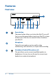
Features Front view Power button The power button allows you to turn the Mini PC on or off. You can use the power button to put your Mini PC to sleep mode or press it for four (4) seconds to force shutdown your Mini PC. Microphone The built-in microphone can be used for video conferencing, voice narrations, or simple audio recording. Headphone/Headset/Microphone jack This port allows you to connect amplified speakers or headphones.
USB 3.2 Gen 2 Type-C™ port This USB Type-C™ (Universal Serial Bus) port provides a transfer rate of up to 10 Gbit/s. This port also supports the Battery Charging 1.2 technology that allows you to charge your USB devices. NOTE: Battery Charging 1.2 technology is only available on selected models, and provides a maximum of 5V / 1.5A output. Memory card slot The built-in memory card reader enables your Mini PC to read and write data to and from Micro SD cards. USB 3.2 Gen 1 port The USB 3.
Left view Air vents (intake vent) The air vents allow cooler air to enter your Mini PC chassis. IMPORTANT: For an optimum heat dissipation and air ventilation, ensure that the air vents are free from obstructions.
Right view Air vents (intake vent) The air vents allow cooler air to enter your Mini PC chassis. IMPORTANT: For an optimum heat dissipation and air ventilation, ensure that the air vents are free from obstructions. Kensington security slot The Kensington security slot allows you to secure your Mini PC using Kensington® security products.
Rear view HDMI port The HDMI (High Definition Multimedia Interface) port supports a Full-HD device such as an LCD TV or monitor to allow viewing on a larger external display. Air vents (exhaust vent) The air vents allow your Mini PC chassis to expel hot air out. IMPORTANT: For an optimum heat dissipation and air ventilation, ensure that the air vents are free from obstructions.
Configurable port This port varies between models and consists of the following port options: VGA port This port allows you to connect your Mini PC to an external display. Serial (COM) connector The 9-pin serial (COM) connector allows you to connect devices that have serial ports such as mouse, modem, or printers. LAN port The 8-pin RJ-45 LAN port supports a standard Ethernet cable for connection to a local network. DisplayPort This port allows you to connect your Mini PC to an external display.
USB 3.2 Gen 1 Type-C™ / DisplayPort / Power (DC) input combo port This USB Type-C™ (Universal Serial Bus) port provides the following: • Transfer rate of up to 5 Gbit/s. • Supports Display port 1.2. Use a USB Type-C™ adapter to connect your Mini PC to an external display. • USB power delivery with a maximum of 5V / 3A output. • Supports power (DC) input when connected to an external device which is PD (Power Delivery) compliant and a 20V / 3.25A output.
Power input The supplied power adapter converts AC power to DC power for use with this jack. Power supplied through this jack supplies power to the Mini PC. To prevent damage to the Mini PC, always use the supplied power adapter. WARNING! The power adapter may become warm to hot when in use. Do not cover the adapter and keep it away from your body.
PN Series
Using your Mini PC 2
Getting started Connect the AC power adapter to your Mini PC To connect the AC power adapter to your Mini PC: A. Connect the power cord to the AC power adapter. B. Connect the DC power connector into your Mini PC’s power (DC) input. C. Plug the AC power adapter into a 100V~240V power source. NOTE: The power adapter may vary in appearance, depending on models and your region.
IMPORTANT! • • • • e strongly recommend that you use only the AC power W adapter and cable that came with your Mini PC. We strongly recommend that you use a grounded wall socket while using your Mini PC. The socket outlet must be easily accessible and near your Mini PC. To disconnect your Mini PC from its main power supply, unplug your Mini PC from the power socket.
Connect a display panel to your device You can connect a display panel or projector to your device that has the following connectors: • VGA connector • DisplayPort • HDMI connector • Thunderbolt 3 connector NOTE: These ports may vary per model. To connect a display panel to your Mini PC: Connect one end of a VGA, DisplayPort, HDMI or Thunderbolt 3 cable to an external display, and the other end of the cable to your Mini PC’s VGA port, DisplayPort, HDMI port, or Thunderbolt 3 port.
Connect display via VGA port Connect display via HDMI port PN Series 23
Connect display via DisplayPortt Connect display via Thunderbolt 3 port 24 PN Series
Connect the USB cable from keyboard or mouse You can connect generally any USB keyboard and mouse to your Mini PC. You can also connect a USB dongle for a wireless keyboard and mouse set. To connect a keyboard and mouse to your Mini PC: Connect the USB cable from your keyboard and mouse to any of the USB ports of your Mini PC. NOTE: The keyboard varies with country or region.
Turn on your Mini PC Press the power button to turn on your Mini PC.
Turning your Mini PC off If your Mini PC is unresponsive, press and hold the power button for at least four (4) seconds until your Mini PC turns off. Putting your Mini PC to sleep To put your Mini PC on Sleep mode, press the Power button once. Entering the BIOS Setup BIOS (Basic Input and Output System) stores system hardware settings that are needed for system startup in the Mini PC. In normal circumstances, the default BIOS settings apply to most conditions to ensure optimal performance.
Load default BIOS settings To load the default values for each of the parameters in your BIOS: • Enter the BIOS by pressing or on the POST screen. NOTE: POST (Power-On Self Test) is a series of software controlled diagnostic tests that run when you turn on your Mini PC. • • • 28 Navigate to the Exit menu. Select the Load Optimized Defaults option, or you may press . Select OK to load the default BIOS values.
3 Upgrading your Mini PC
IMPORTANT! • • I t is recommended that you install or upgrade the memory modules, wireless card, and solid state drive (SSD), under professional supervision. Visit an ASUS service center for further assistance. Ensure that your hands are dry before proceeding with the rest of the installation process. Before installing any of the features in this guide, use a grounded wrist strap or touch a safely grounded object or metal object to avoid damaging them due to static electricity.
Replacing the bottom cover Push the bottom cover from the right side towards the left side of the Mini PC (A), then secure it using the four (4) screws removed previously (B).
Installing memory modules Your Mini PC comes with two SO-DIMM memory slots that allow you to install two DDR4 SO-DIMMs. Align and insert the memory module into the slot (A) and press it down (B) until it is securely seated in place. Repeat the same steps to install the other memory module. IMPORTANT! Refer to http://www.asus.com for the list of compatible DIMMs. You can only install DDR4 SO-DIMMs to the Mini PC’s DIMM slots.
Installing 2.5” HDD or SSD 1. Prepare your 2.5” HDD or SSD, then align it with the storage bay on the bottom cover of your Mini PC. 2. Insert your HDD or SSD into the storage bay (A), then secure it with four (4) screws (B). IMPORTANT! This device only supports 7mm and 9.5mm 2.5” HDD or SSD.
Installing the M.2 SSD (on selected models) 1. Align and insert the 2280 M.2 SSD into its slot inside the Mini PC. 2. Gently push down the 2280 M.2 SSD on top of the screw hole and fasten it using one of the bundled 3mm round screws.
Installing the wireless card NOTE: Your Mini PC includes a M.2 slot for 2230 wireless and Bluetooth modules. Refer to http://www.asus.com for the list of compatible wireless and Bluetooth modules. 1. (optional) Remove the M.2 SSD if an M.2 SSD is installed. To remove the M.2 SSD, remove the screw from the screw hole, then remove the M.2 SSD. 2. Remove the M.2 stand screw. 3.
PN Series
Appendix
Safety information Your Mini PC is designed and tested to meet the latest standards of safety for information technology equipment. However, to ensure your safety, it is important that you read the following safety instructions. Setting up your system • • • • • • • Read and follow all instructions in the documentation before you operate your system. Do not use this product near water or a heated source. Set up the system on a stable surface. Openings on the chassis are for ventilation.
• If you encounter the following technical problems with the product, unplug the power cord and contact a qualified service technician or your retailer. – The power cord or plug is damaged. – Liquid has been spilled into the system. – The system does not function properly even if you follow the operating instructions. – The system was dropped or the cabinet is damaged. – The system performance changes. Lithium-Ion Battery Warning CAUTION: Danger of explosion if battery is incorrectly replaced.
Regulatory notices REACH Complying with the REACH (Registration, Evaluation, Authorization, and Restriction of Chemicals) regulatory framework, we publish the chemical substances in our products at ASUS REACH website at http://csr.asus.com/ english/REACH.htm ASUS Recycling/Takeback Services ASUS recycling and takeback programs come from our commitment to the highest standards for protecting our environment.
Federal Communications Commission Statement This device complies with Part 15 of the FCC Rules. Operation is subject to the following two conditions: • • This device may not cause harmful interference, and This device must accept any interference received including interference that may cause undesired operation. This equipment has been tested and found to comply with the limits for a Class B digital device, pursuant to Part 15 of the FCC Rules.
ISED Radiation Exposure Statement for Canada This equipment complies with ISED radiation exposure limits set forth for an uncontrolled environment. To maintain compliance with ISED RF exposure compliance requirements, please avoid direct contact to the transmitting antenna during transmitting. End users must follow the specific operating instructions for satisfying RF exposure compliance.
Wireless Operation Channel for Different Domains N. America 2.412-2.462 GHz Ch01 through CH11 Japan 2.412-2.484 GHz Ch01 through Ch14 Europe ETSI 2.412-2.472 GHz Ch01 through Ch13 Regional notice for California WARNING Cancer and Reproductive Harm www.P65Warnings.ca.
ENERGY STAR complied product ENERGY STAR is a joint program of the U.S. Environmental Protection Agency and the U.S. Department of Energy helping us all save money and protect the environment through energy efficient products and practices. All ASUS products with the ENERGY STAR logo comply with the ENERGY STAR standard, and the power management feature is enabled by default. The monitor and computer are automatically set to sleep after 10 and 30 minutes of user inactivity.