
User Manual

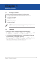
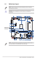
Table Of Contents
- Chapter 1
- Chapter 2
- Chapter 3
- BIOS setup
- 3.1 BIOS setup program
- 3.2 Main menu
- 3.3 Advanced menu
- 3.3.1 Platform Trust Technology
- 3.3.2 Trusted Computing
- 3.3.3 CPU Configuration
- 3.3.4 Graphic Configuration
- 3.3.5 PCI Express Configuration
- 3.3.6 CSM Configuration
- 3.3.7 Super IO Configuration
- 3.3.8 Serial Console Redirection
- 3.3.9 SATA Configuration
- 3.3.10 Network Stack Configuration
- 3.3.11 USB Configuration
- 3.3.12 Onboard Devices Configuration
- 3.3.13 Watchdog Timer
- 3.3.14 APM Configuration
- 3.3.15 EZ-Flash
- 3.3.16 Miscellaneous
- 3.4 Hardware Monitor menu
- 3.5 Security menu
- 3.6 Boot menu
- 3.7 Exit menu
- BIOS setup
- Appendix

J3455T-IM-A/N3350T-IM-A/N4200T-IM-A
2-2
J3455T-IM-A
17.0cm(6.7in)
17.0cm(6.7in)
CHASSIS
SPEAKER
SATA6G_2
SATA6G_1
AT_ATX_SEL
WDT_EN
ATX_5VSB
I2C
CLRTC
ALC887 /
ALC897
AAFP
AUDIO
Super
I/O
M.2(WIFI)
MPCIE_MSATA
8Mb
BIOS
ATX12V
PCIEX1
NANO_SIM
LVDS_EDP
GPIO_CON
KBMS_CON
BKLPWR_SEL
LCD_BLKT_PANEL
VCC_PWR_SEL
F_PANEL
BATTERY
CPU_FAN
CHA_FAN
DC_PWR
COM1_SEL
LPC_DEBUG
SPI_TPM
LAN1_LAN2
DDR3L So-DIMM_B1 (64bit, 204-pin module)
DDR3L So-DIMM_A1 (64bit, 204-pin module)
SATA_PWRCON
USBE12
USBE34
COM1COM2COM3COM4COM5COM6
PANEL_SW
Intel
®
J3455/
N3350/
N4200
SoC
Realtek
®
8111H
Realtek
®
8111H
VGA
U32G1_12
U32G1_34
HDMI
DP
15
12
11
13
14
10
20
17
16
19
18
22
21
24
23
26 25
31
30
29
28
27
1 2 3 4 5 7 8 9 26
2.2 Motherboard layout
Place this side
towards the rear
of the chassis
NOTE: Place four screws into the holes indicated by circles to secure the
motherboard to the chassis.
CAUTION! Do not overtighten the screws! Doing so can damage the
motherboard.
NOTE: The audio codec may vary between motherboards, please consult
your sales window for the motherboards’ exact codec type.