
User Manual


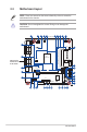

Table Of Contents
- Chapter 1
- Chapter 2
- Chapter 3
- BIOS setup
- 3.1 BIOS setup program
- 3.2 Main menu
- 3.3 Advanced menu
- 3.3.1 LVDS Configuration
- 3.3.2 Video Configuration
- 3.3.3 PCH-FW Configuration
- 3.3.4 Trusted Computing
- 3.3.5 CPU Configuration
- 3.3.6 Graphic Configuration
- 3.3.7 PCI Express Configuration
- 3.3.8 SATA And RST Configuration
- 3.3.9 Network Stack Configuration
- 3.3.10 USB Configuration
- 3.3.11 Onboard Devices Configuration
- 3.3.12 Power Management
- 3.3.13 Super IO Configuration
- 3.3.14 Serial Console Redirection
- 3.3.15 Miscellaneous
- 3.3.16 Realtek PCIe GBE Family Controller (MAC:00:E0:4C:68:00:0B)
- 3.3.17 APM Configuration
- 3.3.18 EZ-Flash
- 3.3.19 Watchdog Timer
- 3.4 Hardware Monitor menu
- 3.5 Security menu
- 3.6 Boot menu
- 3.7 Exit menu
- BIOS setup
- Appendix

N5105I-IM-A
2-2
17.0cm(6.7in)
17.0cm(6.7in)
CHASSIS
AT_ATX_SEL
COM_P80_SEL
COM4_SEL SATA_PWR1
SATA_PWR2COM5_SEL
COM6_SEL
COM_DEBUG
SPEAKER
SATA6G_1 SATA6G_2
CLRTC
ALC
897
AAFP
AUDIO
MPCIE
BUZZER
64Mb
BIOS
ATX12V
ATX12V_OUT
RJ11_VCC_SEL
PCIEX1
LPT
LCD_BLKT_PANEL
LVDS
VCC_PWR_SEL
TPM
GPIO_CON
BKLTEN_SEL
MSR_DAT_SEL
MSR_CLK_SEL
MSR
F_PANEL
BATTERY
CHA_FAN
DC_PWR
RJ11
COM1
COM2
COM3
VGA
DDR4 So-DIMM_B1 (64bit, 204-pin module)
DDR4 So-DIMM_A1 (64bit, 204-pin module)
KBMS_CON
USB_56USB_E12
COM4COM5COM6
MONO_OUT
PANEL_SW
Intel
®
N5105 SoC
RTL
8111H
HDMI
U32G1_34
LAN_U32G1_12
Super
I/O
NANO_SIM
B
B
A
A
17
18
14
13
12
16
15
11
24
20
21
19
23
22
25
26
29 28 27
34
33
32
31
30
1 3 4 52 9 106 7 8
2.2 Motherboard layout
Place this side
towards the rear
of the chassis
NOTE: Place four screws into the holes indicated by circles to secure the
motherboard to the chassis.
CAUTION! Do not overtighten the screws! Doing so can damage the
motherboard.