Intel® NUC Kit NUC11ATKPE Intel® NUC Kit NUC11ATKC4 Intel® NUC Kit NUC11ATKC2 User Guide January 2022 1 NUC11ATKPE, NUC11ATKC4, NUC11ATKC2 User Guide - January 2022
You may not use or facilitate the use of this document in connection with any infringement or other legal analysis concerning Intel products described herein. You agree to grant Intel a non-exclusive, royalty-free license to any patent claim thereafter drafted which includes subject matter disclosed herein. No license (express or implied, by estoppel or otherwise) to any intellectual property rights is granted by this document. All information provided here is subject to change without notice.
Contents 1.0 Introduction ............................................................................................................................. 5 1.1 1.2 1.3 Before You Begin ........................................................................................................................................... 5 Installation Precautions .............................................................................................................................
Revision History Date January 2022 Revision 1.0 Description Initial release.
1.0 Introduction This User Guide provides step-by-step installation instructions for these products: 1.1 Intel® NUC Kit NUC11ATKPE Intel® NUC Kit NUC11ATKC4 Intel® NUC Kit NUC11ATKC2 Before You Begin CAUTIONS The steps in this guide assume you’re familiar with computer terminology and with the safety practices and regulatory compliance required for using and modifying computer equipment.
To avoid injury, be careful of: Sharp pins on connectors Sharp pins on circuit boards Rough edges and sharp corners on the chassis Hot components (such as SSDs, processors, voltage regulators, and heat sinks) Damage to wires that could cause a short circuit Observe all warnings and cautions that instruct you to refer computer servicing to qualified technical personnel. 1.
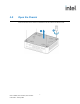
2.0 Open the Chassis Unscrew the four corner screws on the bottom of the chassis and lift the cover.
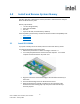
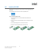
3.0 Install and Remove System Memory Intel NUC Kits NUC11ATKPE, NUC11ATKC4, and NUC11ATKC2 have two 260-pin DDR4 SO-DIMM memory slots Memory requirements: 1.2V low voltage memory 2933 MHz SO-DIMMs Non-ECC Up to 32 GB total (2x 16GB memory modules) Find compatible system memory modules at the Intel® Product Compatibility Tool: 3.1 NUC11ATKPE NUC11ATKC4 NUC11ATKC2 Install SO-DIMMs If you plan to install just one SO-DIMM, install it in the lower memory socket.
3.2 Remove SO-DIMMs To remove a SO-DIMM, follow these steps: 1. 2. 3. 4. 5. 6. 7. 8. Observe the precautions in "Before You Begin" in Section 1.1. Turn off all peripheral devices connected to the computer. Turn off the computer. Remove the AC power cord from the computer. Remove the computer’s cover. Gently spread the retaining clips at each end of the SO-DIMM socket. The SO-DIMM pops out of the socket. Hold the SO-DIMM by the edges, lift it away from the socket, and store it in an anti-static package.
4.0 Install an M.2 SSD Intel NUC Kits NUC11ATKPE, NUC11ATKC4, and NUC11ATKC2 support 80mm and 42mm SSDs. Find compatible M.2 SSDs at the Intel® Product Compatibility Tool: NUC11ATKPE NUC11ATKC4 NUC11ATKC2 If you’re installing an 80mm M.2 SSD: 1. Remove the small silver screw from the 80mm metal standoff on the motherboard. 2. Align the small notch at the bottom edge of the M.2 card with the key in the connector. 3. Insert the bottom edge of the M.2 card into the connector. 4.
If you’re installing a 42mm M.2 SSD: 1. Remove the small silver screw from the metal standoff on the motherboard. 2. Move the standoff from the 80mm position to the 42mm position. 3. Align the small notch at the bottom edge of the M.2 card with the key in the connector. 4. Insert the bottom edge of the M.2 card into the connector. 5. Secure the card to the standoff with the small silver screw.
5.0 Close the Chassis After all components have been installed, close the Intel NUC chassis. Intel recommends this be done by hand with a screwdriver to avoid over-tightening and possibly damaging the screws.
6.0 Use the VESA Bracket (Optional) Follow these instructions to attach and use the VESA mount bracket: 1. Using the four small black screws that were included in the box, attach the VESA bracket to the back of the monitor or TV. 2. Attach the two slightly larger black screws to the bottom chassis cover of the Intel NUC.
3. Slide the Intel NUC onto the VESA mount bracket.
7.0 Connect Power Country-specific power plug attachments are included in the box. 1. Choose the attachment for your region. 2. Connect AC power. Each Intel NUC model includes either a region-specific AC power cord or no AC power cord (only the power adapter). Product codes Power cord type BNUC11ATKPE000 No power cord included. An AC power cord needs to be purchased separately. Power cords are available at many Internet sites for use in multiple countries.
BNUC11ATKPE001 US power cord included. BNUC11ATKC4001 BNUC11ATKC4001 BNUC11ATKPE002 EU power cord included. BNUC11ATKC4002 BNUC11ATKC4002 BNUC11ATKPE003 UK power cord included. BNUC11ATKC4003 BNUC11ATKC4003 BNUC11ATKPE004 Australia/New Zealand power cord included. BNUC11ATKC4004 BNUC11ATKC4004 BNUC11ATKPE006 China power cord included.
8.0 Install an Operating System See Supported Operating Systems for a list of Intel-validated Windows* operating systems. The Intel Product Compatibility Tool lists versions of Linux* that have been reported as compatible by Intel NUC owners. If you need assistance with Linux on your Intel NUC, check the distribution’s website and forums for peer assistance. Refer to Operating System Installation for system requirements and installation steps.
9.0 Install the Latest Device Drivers and Software Here are the options for keeping device drivers current: Allow the Intel® Driver & Support Assistant (Intel® DSA) to detect out-ofdate drivers Manually download drivers, BIOS, and software from Download Center: o o o NUC11ATKPE NUC11ATKC4 NUC11ATKC2 The following device drivers and software are available.