
User Manual

vii
Contents
Revision History ............................................................................................................... ii
Disclaimer .................................................................................................................................................................. ii
Preface .............................................................................................................................. iii
Intended Audience ................................................................................................................................................ iii
What This Document Contains ........................................................................................................................ iii
Typographical Conventions .............................................................................................................................. iii
Intel® NUC 8 Compute Element Identification Information .................................................................. v
Specification Changes or Clarifications ........................................................................................................ vi
Errata ........................................................................................................................................................................... vi
Contents .......................................................................................................................... vii
2 Product Description .................................................................................................. 9
2.1 Overview ......................................................................................................................................................... 9
2.2 Version Summary ........................................................................................................................................ 9
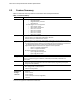
2.3 Feature Summary ..................................................................................................................................... 10
3 Technical Reference ............................................................................................... 12
3.1 Block Diagram ............................................................................................................................................ 12
3.2 Compute Element Exterior ................................................................................................................... 13
3.3 Connector .................................................................................................................................................... 14
3.3.1 Connector Pin-Out ................................................................................................................ 15
3.4 Antenna Connection ............................................................................................................................... 19
3.5 BIOS Security Switch............................................................................................................................... 19
3.6 Power............................................................................................................................................................. 21
3.7 Mechanical .................................................................................................................................................. 21
3.8 Thermal ........................................................................................................................................................ 23
3.9 Environmental ........................................................................................................................................... 24
4 Characterized Errata ............................................................................................... 25
Figures
Figure 1. Block Diagram ........................................................................................................................................... 12
Figure 2. Integrated Heat Shield Side ................................................................................................................ 13
Figure 3. Mylar Side ................................................................................................................................................... 13
Figure 4. Connector with Pinout – Mylar Side ................................................................................................ 14
Figure 5. Connector with Pinout – IHS Side .................................................................................................... 14
Figure 6. Location of the Antenna Connectors .............................................................................................. 19
Figure 7. Location of the BIOS Security Switch ............................................................................................. 20
Figure 8. Mylar Side ................................................................................................................................................... 21