P/I-AP55T Mainboard User's Manual
Copyright This Product, Including Any Software And Documentation, May Not, In Whole Or In Part, Be Copied, Photocopied, Translated Or Reduced To Any Electronic Or Machine-Readable Form Without Prior Written Consent From ASUSTek Computer Inc., Except For Copies Retained By The Purchaser For Backup Purposes. No Warranty Or Representation, Either Expressed Or Implied, Is Made With Respect To This Documentation, Its Quality, Performance, Merchant ability, Or Fitness For A Particular Purpose.
Table of Contents Chapter 1: Feature Guide..........................................1-1 The P/I-AP55T Package.................................................................1-2 Main Features................................................................................. 1-3 Bundled Software...........................................................................1-5 Static Electricity Precautions........................................................ 1-5 Mainboard Layout.................................
P/I-AP55T User’s Manual IDE HDD Auto Detection......................................................3-26 Save And Exit Setup............................................................... 3-28 Exit Without Saving...............................................................3-28 NCR SCSI BIOS & Drivers......................................................... 3-29 Flash Memory Writer Utility...................................................... 3-30 Chapter 4: Technical Summary..............................
Feature Guide This manual explains how to use this system mainboard and in stall upgrades. It has an overview of the design and features of the board and provides useful information if you want to change the con figuration of the board, or a system it is installed in.
P/I-AP55T User's Manual If you want to change the existing configuration, consult all of your system documentation. Also be certain that opening up and working on the system yourself won't violate your system warranty. Most system vendors do allow you to open the system to install ex pansion cards or additional peripheral equipment. This manual provides all the information you need to upgrade or change the setup of the board.
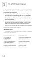
Feature Guide Main Features The P/I-AP55T has many performance and system features in tegrated onto the mainboard, including the following: • Supports 75, 90,100,120,133,150 or 166MHz Pentium CPUs in a ZIP Socket 5 or 7. Pentium P55CT CPUs require the ZIP Socket 7 and Header 7 VRM sockets. • Intel Triton chipset • Uses 72-pin SIMM modules of 4, 8,16, or 32MB in configura tions up to 128MB using either Past Page Mode or Extended Data Output (EDO) DRAM.
P/I-AP55T User's Manual Onboard Creative Technology Vibra 16S soimd card with ex ternal port module provides 16-bit SoimdBlaster audio and onboard sound connections for several CD-ROM drives. Ex ternal module has Microphone, Line-in, Speaker and Game ports and volume control. Software drivers and utilities pro vided are explained in accompanying \^deo/Audio manual.
Feature Guide Bundled Software This mainboard comes with a variety of support software. The BIOS Support Disk has a readme file on it with the latest information on upgrading the BIOS, as explained in Chapter 3 of this manual. The Video/Audio manual that comes with this mainboard explains how to install and use the software for the VGA and audio features. The software includes: • PFlash Memory Writer — updates the system BIOS with a new BIOS file.
P/I-AP55T User’s Manual To protect the mainboard and other components against damage from static electric discharge, you should follow some basic precau tions whenever you handle them: 1. Use a grounding wrist strap. The strap will have an 'alligator' clip at the end of a shielded wire lead. Clip it to a grounded object. Any static electricity will then harmlessly discharge through the strap. Put on and connect the strap before you handle the components. 2. Use an anti-static pad.
Feature Guide P/I-AP55T Layout O CD (DCDCD 1-7
P/I-AP55T User's Manual Using Your Mainboard In addition to the operating instructions in your system manual, there are a few additional things specific to the mainboard you will need to know. These have to do with the hardware settings on the mainboard and the system configuration record. Hardware Settings There are a number of hardware settings on the board. They specify configuration options for various features. The settings are made using something called a 'jumper'.
Feature Guide Setting options for most jumpers are printed on the board in a stylized bird's-eye view, with which pins to connect for each setting marked by a bar connecting two pins. For example, if a jumper has three pins, connecting, or 'shorting', the first and second pins creates one setting and shorting the second and third pins creates another. The same type of diagrams are used in this manual.
P/I-AP55T User’s Manual The System Configuration Record All personal computers use a BIOS (Basic Input Output System) as the basic software that tells the computer how to function. In or der for the BIOS to function, there has to be a record of the computer's hardware and configuration settings for it to refer to. This record is created by using a software program permanently stored in the BIOS ROM chip on the mainboard. The program is called the BIOS Setup Utility.
Feature Guide System IRQs Later in the manual you'll see something called an "IRQ" men tioned several times. If you're not familiar with these, this is a short explanation of what they are and why you may need to know about them if you upgrade your system. An IRQ, or interrupt request, is the process whereby an input or output device tells the CPU to temporarily interrupt whatever it is doing and immediately process something from the source of the interrupt.
P/I-AP55T User's Manual BIOS-Supported Enhanced IDE Features The BIOS has several feature enhancements for IDE hard disk drives and support for other ГОЕ devices. ,The original IDE implementation was limited to two hard disk drives with relatively slower data transfer rates.
Feature Guide Large IDE Hard Disks For ГОЕ hard disk drives, the BIOS provides three modes to sup port both normal IDE hard disks and also drives larger than 528MB: Normal - for IDE drives smaller than 528MB Large - for drives larger than 528MB that do not use LBA. These can only be used with the MS-DOS operating system. LBA - for drives larger than 528MB and up to 8.4 GB (GigaBytes) that use Logic Block Addressing mode. Other IDE Devices Enhanced IDE allows the use of IDE devices other than hard disks.
P/I-AP55T User’s Manual Dual IDE Channel Support With the onboard ГОЕ controller you can connect up to four ГОЕ peripheral devices to your system. With Enhanced ГОЕ you can con nect two devices to each connector. All devices are categorized the saíne way IDE hard disks have been in the past, with one device set as the "Master'' device and the second as the "Slave" device. These two charmels are called the "Primary" and the "Secondary" channel. The Primary channel uses IRQ14, the Secondary, IRQ15.
Feature Guide Onboard VGA & Audio Features The onboard VGA display and audio features come with exten sive software drivers and utilities. The other manual in the mainboard package explains how to install and use the software for these fea tures. There is information on the hardware setup for these features in Chapter 4 of this manual. VGA Hardware & Software The onboard VGA display is capable of displaying multiple reso lutions and color depths (numbers of colors) at a variety of refresh rates.
P/I-AP55T User's Manual SCSI BIOS Firmware & The Optional SC-200 Controller Card This mainboard has onboard NCR SCSI firmware recorded in the BIOS flash ROM chip that supports the NCR 53C810 PCI Fast SCSI2 controller. There is an optional SCSI controller card, the SC-200 that uses this firmware. The NCR SCSI controller is a full 32-bit PCI DMA bus master and supports the ASPI and CAM standards. You can connect a chain of up to seven devices to the SCSI inter face.
This section explains how to install options on your mainboard. It covers the most likely and technically accessible upgrades you might want to do, including installing expansion cards, adding sys tem or video memory, installing ГОЕ devices and upgrading the CPU. Installing upgrades will either improve the performance of your computer, or add some additional capabilities to it. You can install upgrades yourself, or have your dealer or a qualified computer ser vice technician do it for you.
P/I-AP55T User’s Manual Before you start, always make sure the computer is turned off. You should also make sure to observe standard static electricity dis charge precautions. You can damage your expansion card, the mainboard, or both by not being careful about this. ' The basic procedure for installing expansion cards is the same for both ISA and PCI cards. The basic procedure is as follows: 1. Open the system case to gain access to the expansion slots. 2.
upgrade Guide Assigning System IRQs for Expansion Cards Cards for both the ISA and PCI buses may need to use IRQs. You must configure any IRQ assignments so that the system can know which IRQ is assigned to which card. IRQs must be assigned correctly or the mainboard will not work properly. As mentioned in Chapter 1, there are 16 IRQs. Some of them are already in use by standard parts of the system such as the keyboard or mouse. IRQs 5,10 and 11 are not used by the mainboard and are available.
P/I-AP55T User's Manual Installing Expansion Cards That Use An IRQ Example PCI installation procedure: 1. Choose a slot to usee.g. PCI Slot 1 - fixed INT A# 2. Make sure Slot 1 is setto the "Auto" setting 3. Configure the card you will install in PCI Slot 1 to use INT A and install it Example ISA installation procedure: 1. If it is a Legacy card, select the ISA IRQ it will use. If PNP card, skip this. e.g. IRQ 5 2. If it is a Legacy card, set IRQ 5 as used by ISA in PCI and PNP Setup, or use ICU.
upgrade Guide Upgrading System Memory This section explains how to install system memory. There are instructions on how to configure and install memory and an expla nation of the technical specifications required. System DRAM is the main source of data for the CPU. Data re mains stored in DRAM as long as the system is turned on, and is lost when you turn it off. The Level 2 cache memory is Static RAM (SRAM), which is faster than DRAM memory. When the CPU looks for data, it first searches the cache.
P/I-AP55T User's Manual Configuring System Memory If you want to add system memory, you must use the configura tion options and specifications shown in this section. Memory Combinations You can configure the system memory in a variety of ways, us ing different combinations of SIMM modules. Using the 4 SIMM sockets there are many configuration options. The following chart shows the supported combinations. The only restrictions are: • You must use 2 sockets at a time, in sequence, i.e.
upgrade Guide Memory Module Combinations BankO Sockets 1&2 Banki Sockets3&4 Total Memory Using Sockets 1 through 4 4MB X 2 None 8MB* 8MBx2 Mone 16MB* 16MB X 2 None 32MB* 32MB X 2 None 64MB* * Note: The configurations above can use Bank 1 and leave Bank 0 empty instead 4MBx2 4MBx2 16MB 4MBx2 8MB X 2 24MB 4MBx2 16MB X 2 40MB 4MBx2 32MB X 2 72MB 8MB X 2 4MBx2 24MB 8MB X 2 8MB X 2 32MB 8MB X 2 16MB x 2 48MB 8MB X 2 32MB X 2 80MB 16MBx2 4MBx2 40MB 16MBx2 8MB X 2 48MB
P/I-AP55T User’s Manual Installing SIMMs To install SIMMs follow these instructions: 1. The modules will only insert in a socket in one orientation. An - orientation cut-out will prevent you from inserting them the wrong way. See the figures at right. 2. Press the module edge connector into the socket at a moder ate angle to the board. See the figures below. 3.
Cut-out SIMMs have a cut-out at one end that matches an extension on one of the vertical posts of e a c h socket. Put orientation cut-out at this end. SIMM# 4 3 2 1 V T £ E Install modules starting with the SIMM1 socket on the righthand side. Modules may have chips on one or both sides.
P/I-AP55T User's Manual Upgrading Video DRAM Memory The mainboard comes with 1MB of video display DRAM mounted on it. In addition, there are two expansion sockets that al low you to expand the video display memory to 2MB. To expand the video display memory, you must install two 512KB DRAM chips in the expansion sockets. To install the chips, observe static discharge precautions and do as follows: 1. Open your system case and find the video display memory ex pansion sockets, located near the monitor port.
upgrade Guide Installing IDE Hard Disks This section explains how to install IDE hard disk drives or other devices. You can connect up to four ГОЕ devices to the onboard con nectors. This section explains the information specific to this mainboard, not the basic procedure for how to install a hard disk in your system. Your system manual should have instructions specific to installing devices in your case.
P/I-AP55T User’s Manual Installing Additional IDE Devices If you have space in your system case, you can install another ГОЕ hard disk or other IDE device using the procedure on the previous page. Install the drive in an empty drive bay and cormect the drive to the unused middle connector of the ГОЕ ribbon cable. Note that a second IDE device on a channel must be set to function as a "slave" device, because the first ГОЕ device functions as the "master" device.
upgrade Guide Updating the Flash BIOS This mainboard has two BIOS ROM chip options. It can use ei ther of two programmable 'flash' EPROM chips, 5-volt or 12-volt, either of which you can update when BIOS upgrades are available. Jumper JP9 enables programming for the BIOS ROM chip. There are two settings. The default setting, which shorts pins 1&2, is for Write-Protect/Normal Read. The other setting, which shorts pms 2&3, is for Enable Programming.
P/I-AP55T User's Manual Installing a Pentium Upgrade If yoiir mainboard has a "Socket 7" ZBF socket and Header 7 VRM (Voltage Regulator Module) socket, you can install a Pentium upgr,ade processor ruiming at either 150MHz or 167MHz. The upgrade package will consist of the Pentium CPU and the required VRM. To install an upgrade processor, follow the instructions that come with the upgrade. Remember to take careful precautions against static electric discharge. The basic procedure will be as follows: 1.
Software Guide This chapter explains the Setup Utility for the Award BIOS, the SCSI BIOS and drivers, and the system BIOS flash memory update utility. Award BIOS Setup All computer mainboards of this type have a 'Setup' utility pro gram stored in the BIOS ROM that is used to create a record of the system configuration and settings. If you received your mainboard installed as part of a system, the proper entries have probably already been made.
P/I-AP55T User's Manual After you press the key the main program screen will ap pear, displaying the following choices. Main Program Screen ROM PCI/ISA BIOS{PI-5XTP4: CMOS SETUP tJTILITY AWARD SOFTWARE,INC.
Software Guide Standard CMOS Setup "STANDARD CMOS SETUP" records some basic system hard ware information and sets the system clock and error handling. If your mainboard is already installed in a working system you will not need to do this. If the configuration record which gets stored in the CMOS memory on the board is lost or corrupted, or if you change your system hardware configuration, you will need to recreate the record.
P/I-AP55T User's Manual "STANDARD CMOS SETUP" displays a screen with a list of en tries. Follow the on-screen instructions to move around the screen. Instructions at the bottom of the screen list the controls for this screen. Use the arrow keys to move between fields, and the ('PU')/ (TD') or plus and minus keys to change the op tion shown in the selected field. Pressing + changes the color scheme of the display, and exits this level and returns to the main screen.
Software Guide If you have one or more SCSI hard disks installed in your system, you do not need to enter their specifications here. SCSI drives oper ate using device drivers and are not supported directly by any cur rent PC BIOS. If your mainboard has the SCSI controller card option, and you will use it, see the SCSI instructions that follow later in this section. If you have some other SCSI controller, follow the instruc tions that came with it on how to install any required SCSI driver.
P/I-AP55T User's Manual Mode Setting For Hard Disk Drives Larger Than 528MB The last of the specification entries. Mode, requires additional explanation. The Mode settings are for ГОЕ hard disks only. You can ignore this item for MFM and ESDI drives. There are three entries you can select from in the Mode field, "Normal", "Large" and "LBA". Set Mode to the Normal setting for ГОЕ hard disk drives smaller than 528MB.
Software Guide Video Display Types ''Video" refers to the type of video display card your system has. The options are: EGA/VGA Mono (for Hercules or MDA) CGA 40 CGA 80 You should select the setting that matches your video display card. If you have a VGA or any higher resolution card, choose the EGA/VGA setting. Error Handling The last line "Halt On" controls whether the system stops in case of an error.
P/I-AP55T User’s Manual BIOS Features Setup "BIOS FEATURES SETUP" is a list of system configuration op tions. Some entries are defaults required by the mainboard's design. Others will improve your system's performance if enabled, or let you set up some system features according to your preference. BIOS Features Setup Screen ROM PCI/ISA BIOS(PI-5XTP4) BIOS FEATURES SETUP AWARD SOFTWARE INC.
Software Guide Virus Protection The "Virus Warning" default setting is "Disabled". This feature protects the boot sector and partition table of your hard disk. Any attempt to write to them will halt the system and cause a warning message to appear. If this happens, you can either allow the opera tion to continue or stop it and use an anti-virus utility on a virus-free bootable floppy disk to reboot and investigate your system.
P/I-AP55T User's Manual The default "Boot Up NumLock Status" setting is "On". When the computer boots, the numbers on the numeric keypad of an IBMcompatible extended keyboard will be active. If you turn this off the keypad cursor controls will be active. ' "Boot Up System Speed" sets the CPU speed at boot up. The de fault setting is "High". IDE Modes The "IDE HDD Block Mode" default setting is "Enabled".
Software Guide Password Control The "Security Option" controls the Password Setting in the main screen. The default setting is "System", uses the User Password fea ture every time you boot up. The other setting is "Setup". This will allow the system to boot, and use the Supervisor Password only to protect the Setup Utility settings from being tampered with. You cre ate a password by using the Supervisor or User Password command from the main screen as explained later in this section.
P/I-AP55T User’s Manual Chipset Features Setup This screen controls the settings for the mainboard's chip set. The controls for this screen are the same as for the previous screen. Chipset Features Screen ROM PCI/ISA BIOS(PI-5XTP4) CHIPSET FEATURES SETUP AMARD SOFTWARE INC.
Software Guide Controller Settings The default setting for "Onboard IDE Timing" is "Fastest", which provides optimum performance for Enhanced ГОЕ Modes 3 and 4. К the hard disk drive(s) installed in your system can not use the fcistest timing, you should change the setting to "Fast". If you have any hard disk installed that does not support Mode 3 and 4 timing, you should set this line to the "Standard" setting. Note: This line also has a "Disable" setting.
P/I-AP55T User’s Manual Serial Ports The "Onboard Serial Port 1" and "Onboard Serial Port 2" lines control the assignments for the mainboard's two onboard serial con nectors.
Software Guide ECP DMA Select If you select the ECP parallel port feature on the previous line, the BIOS will auto-select DMA channel 3 for the "ECP DMA Select" line. This line does not appear unless the ECP feature is selected. UART2 Use Infrared * The default setting for the "UART2 Use Infrared " is "Disabled". The default setting leaves the second serial port UART set to support the Serial Port 2 connector.
P/I-AP55T User's Manual Power Management Setup Power Management Setup controls the mainboard's "green" fea tures. The features shut down the video display and hard disk to save energy. THb Power Management Setup Screen ROM PCI/ISA BIOS (PI-5XTP4) POWER MANAGEMENT SETUP AWARD SOFTWARE INC.
Software Guide Min Saving Another set of power saving assignments which activate each after a moderate period of system inactivity. Disable Turns off all power saving User Defined Allows you to set power saving options ac cording to your requirements. (Default) Max Saving The "Max Saving" defaults are "1 Min" and "1 Min". Min Saving The "Min Saving" defaults are "20Min" and "1 Hour". Video Off The "Video Off Option" default is "Susp,Stby-> Off".
P/I-AP55T User’s Manual Suspend Switch The "Suspend Switch" default is "Enable". This enables the SMI connector on the mainboard. The SMI connector connects to the lead from a Suspend switch mounted on the system case. Doze & Standby Speeds The next two lines set the speed the CPU will operate at during each mode. The number indicates what the normal CPU speed is di vided by. PM Timers The next lines control the time-out settings for the Power Man agement scheme.
Software Guide PM Events If there is activity on any of the IRQs listed in the left-hand group while the system is suspended, the system will wake up if that IRQ is Enabled. You can enable power management for IRQs 3-15 indi vidually in the list at the right of the screen. The power management scheme will work on the enabled IRQs. Note: Normally, a Microsoft serial mouse or compatible will use either COMl (IRQ4) or COM2 (IRQ3) and a PS/2-type mouse will use IRQ12.
P/I-AP55T User's Manual PCI and PNP Configuration Setup This screen configures the PCI Bus slots. All the slots use INTA#. If you install a card , you should set the card to INTA#. PCI And PNP Configuration Setup Screen ROM PCI/ISA BIOS(PI-5XTP4: PCI AND PNP SETUP AWARD SOFTWARE INC.
Software Guide The next line is the "PCI Latency Hmer" setting. Do not change the "80 PCI Clock" setting. This default setting enables maximum PCI performance for this mainboard. Plug And Play The seven "IRQ ... Used By ISA" lines indicate whether or not the IRQ indicated for each line is being used by a 'legacy' (non-PnP) ISA card.
P/I-AP55T User's Manual If you have a legacy ISA card that uses any memory segment in the C800h to DCOOh address range and you have not used an ICU to specify the range it uses, you should set the base address and block size by using the "ISA MEM Block BASE" line. When you select a base address from the six options, the "ISA MEM Block SIZE" line will appear and you can select a block size from the four options.
Software Guide Load BIOS Defaults "LOAD BIOS DEFAULTS" loads the troubleshooting default values permanently recorded in the BIOS ROM. ITiese settings are non-optimal and turn off all high performance features. The Standcird CMOS Setup screen is not affected. To use this fea ture, highlight it on the main screen and press . A line will appear asking if you want to load the BIOS default values. Press the key and then . The default settings will load.
P/I-AP55T User's Manual Load Setup Defaults The "LOAD SETUP DEFAULTS" option loads optimized set tings from the BIOS ROM. Use this option to load default settings for normal use. The Setup Defaults default settings do not affect the Standard CMOS Setup screen. To use the Setup Defavdts, highlight the entry on the main screen and press . A line will appear asking if you want to load the Setup default values. Press the key and then press . The Setup Defaults will load.
Software Guide Setting Supervisor & User Passwords The "SUPERVISOR PASSWORD" and "USER PASSWORD" options set passwords. The Supervisor Password is for system and Setup Utility access. The User Password is for the system only. The mainboard ships with no passwords. To create a password, highlight the type you want and press the key. At the prompt, type your password. The password is case sensitive, and can be up to 8 alphanumeric characters.
P/I-AP55T User’s Manual IDE HDD Auto Detection If your system has an IDE hard drive, you can use this utility to detect its parameters and enter them into the Standard CMOS Setup automatically. This utility will detect as many as four IDE drives if your system configuration supports that many. In sequence, a set of parameters for each drive will appear in the box. To accept the entries displayed press the Y key, to skip to the next drive, press the N key.
Software Guide IDE HDD Auto Detection Screen ROM PCI/ISA BI0S(P1-5XTP4) CMOS SETOP UTILITy AHARD 50PTHARE,INC. HARD DISKS TYPE SIZE CYLS HEADS PRECOKP LANDZ SECTOR MODE Primary Master: Select Primary Master Option (M«Skip) ? N OPTIONS SIZE KY) 307 CYLS. HEADS PIUSCOKP LANDZONB SECTORS MODE 790. 15 65535 790 57 NORMAL Important!: This utility will only detect one set of parameters for an ГОЕ hard drive. Some ГОЕ drives can use more than one set.
P/I-AP55T User's Manual Save And Exit Setup The next selection on the Utilities menu is "SAVE AND EXIT SETUP". If you select this and press the key the values en tered during the current session will be recorded in the CMOS memory on the mainboard. The system will check it every time you turn your system on and compare it to what it finds as it checks the system. This record is required for the system to operate.
Software Guide NCR SCSI BIOS & Drivers The NCR 53C810 SCSI BIOS is recorded on the same flash memory chip as the system BIOS. To use the onboard NCR SCSI BIOS, the optional SC-200 SCSI controller card must be installed in your system. All SCSI devices you connect to your system require driver soft ware. The NCR SCSI BIOS directly supports SCSI hard disks imder DOS, Windows and OS/2.
P/I-AP55T User’s Manual Flash Memory Writer Utility Your mainboard comes with a utility to upgrade the BIOS. The BIOS is stored on a 'flash' EPROM BIOS ROM chip on the mainboard that can be erased and reprogrammed. This is what the Flash Memory Writer (FMW) utility does. The utility is in the "Flash" directory on the DOS-formatted support floppy disk that comes with the mainboard. You will find three files in the directory: PFLASH.
Software Guide 2. Make sure the CPU is running in 'real mode'. FMW will not run if the CPU is operating in protected or vir tual mode. This means that you can not run it with Windows running or with any memory manager software (including HIMEM.SYS). You must disable any memory manager soft ware first. The easiest way to do this is to: a. Boot your system from a bootable floppy disk with no config.sys or autoexec.bat files and then run Flash Memory Writer from a backup copy of your support disk.
P/I-AP55T User’s Manual The Flash Memory Writer Utility Screen ASUSTek PHP BIOS FLASH MEMORY WRITER VI.0 Copyright (C) 1995, ASUSTek COMPUTER Inc Flash Type -- SST 29EE010 Current BIOS Revision: #401X0-0109 Choose one of the following: 1. Save Current BIOS To File 2. Update BIOS Main Block From File 3. Advanced Features Enter Choice: [1] Press BSC To Exit There are three command options which you invoke by typing the number of the command and pressing the "Enter" key: 1.
Software Guide There is a line at the bottom of the screen 'Tress ESC To Exit". If you press the Escape key the program will terminate and re turn you to the DOS prompt. If you type a "3" and then press the "Enter" key the Advanced Features screen will appear. The Advanced Features Screen Advanced Features Flash Type -- SST 29EE010 Current BIOS Revision: t401A0-0I09 Choose one of the following: 1. Clear PHP ESCD Parameter Block 2.
P/I-AP55T User's Manual Follow this procedure to update the Plug and Play system BIOS: 1. Back up your existing system BIOS by using the "Save Current BIOS To File" command. Type "1" and press "Enter" to execute the command. A second screen will appear. Type the BIOS file name, e.g. TR5A0109.AWD, press "Enter" and the program will write a file containing the current BIOS to the directory you are nmning FMW from. 2. Install the new BIOS using the "Update BIOS Main Block From File" command.
Technical Summary This section provides additional information on the technical specifications of the mainboard. The second part explains how to set up the optional PCI-SC200 SCSI Interface card. Jumper Setting Summary Base Address Selector: JP1 & JP2 These jumpers set the base address for the onboard audio. JPl JP2 220h 2&3 2&3 240h 2&3 1&2 260h 1&2 2&3 280h 1&2 1&2 OO C. T7 CSJ c. -o 1 1 2 ^5 N» o $ o $ 220h 240h o 0 $ $ o ® $ 0 0 o o 260h Sg c.
P/I-AP55T User's Manual Bus & CPU External Clock Speed Selector: JP4, JP5 & JP6 Set these according to the Bus clock and the CPU's external clock speed Ext Clock JP4 JP5 JP6 Int. Clk Speed 66Mhz 2&3 1&2 2&3 100/133/167MHz 60Mhz 2&3 2&3 1&2 90/120/150MHz SOMhz 1&2 2&3 2&3 75MHz Note: CPUs are normally listed by their /nferna/clock speed. You MUST also set JP11 & 12 for the correct multiple of the external clock speed.
Technical Summary Flash EPROM Voltage Selector: JP8 This jumper is factory set for the type of EPROM chip installed. JP8 +5V 1&2 +12V 2&3 JP8 JP8 o o +5-Volt EPROM +12-Volt EPROM Flash EPROM Read/Write Selector: JP9 This jumper selects between Normal Read/Write Protected mode and Program ming Enabled mode for the BIOS flash EPROM. JP9 Normal / W. Protect 1&2 Programming Enabled 2&3 © o ■ C"O CO (T) Normal Read Write Protect Default o .
P/I-AP55T User's Manual Level 2 Cache Size: JP10 This is factory- set based on the size of the cache mounted on the mainboard. JPIO 256K 1&2 512K 2&3 to CJl a> 7^ cn ro O 7^ ro CJ1 03 7^ O cn ^% 2S6KB Cache 512KB Cache CPU Internal Clock External Mulitple Salector: JP11 & JP12 The default setting is for 75MHz, 90Mhz and 100MHz Pentium CPUs. CPU Internal Clock J P l l JP12 Int. Clock = 1.5 X Ext Clock Open Open 75/90/100 Int Clock s 2 X Ext Clock Short Open 120/133MHZ Int. Clock = 2.
Technical Summary RTC Clear CMOS Memory: JP13 You can use this jumper to clear the CMOS memory that stores the BIOS Setup Utility configuration record, including any passwords. After clearing the CMOS memory you must run the BIOS Setup Utility again to create and store a new configuration record. JP13 Normal Open Clear Short OO “D CO Normal 0© 2 CO Clear CMOS memory Voltage Regulator Type Selector JP15 This jumper sets which type of voltage regulator is installed on the mainboard.
P/I-AP55T User's Manual Voltage Regulator Output Selector: JP16, JP17 These set the CPU voltage and are factory-set for the installed CPU. JP16 JP17 STD/VR Short Open Default VRE Open Short IMPORTANT: You must set these jumpers correctly for the CPU's voltage type or your system will operate improperly. O O o o 1 1 JP1 7 . P16 JPl 7 . P16 3.3V +5% STO/VR 3.4V-3.
Technical Summary COM 2 Mode Selector: JP24 & JP25 These set COM2 to support either an RS-232 serial port or an Infrared (IR) port JP24 JP25 RS-232 1&2 1&2 Memory Subsystem Memory Specifications: See pages 2-7. Memory Configurations See page 2-8 for a chart of the configuration options.
P/I-AP55T User's Manual External Connections There are several connectors on the board for switches and indicator lights from the system case. The connectors are made of the same components as the jumper switches. There are also connectors for the on-board I/O ports and the leads from a 5-volt system power supply. Connector Block: Power LED Connector for a Power-On indicator LED lead SMI Switch Connector for a Suspend switch lead. SMO Signal Connector for a Suspend mode indicator.
Technical Summary Connector Locations Audio Module Connector TItJ 1I ^ CD-ROM audio connectors I Infrared connector Wave Table Connector CPU Fan & CMOS clear IDE LED connector Connector block Connector Block [Pin 1 Corner] Power LED o O o o o o7^ oo oo o o o "0 o> oo m oo Keylock o SMI Suspend Switch s 00 SMO Suspend Signal 00 m 3D Reset m 00 Speaker 3D 4-9
P/I-AP55T User's Manual Other Feature Connectors O O oo 2 CPU Fan power lead connector (+12V) o o o o o RTC clear CMOS memory oo IDE LED JO o o IrDA infrared module connector IDE LED activity light connector Audio Connectots LGGR o a SONY oooo -o Panasonic CD-ROM R > > drive audio lead G CO connector L o o o o MTM o o o o SONY CD-ROM drive audio lead connector G R G L Pin Assignments G; Ground L: Left Channel R: Right Channel 4-10 Mitsumi CD-ROM drive audio lead connector
External Audio Module Game port Pini Module ribbon cable connects to AUDIO CON. on mainboard Speaker jack Volume control Line-in jack Microphone jack The external audio module installs in an empty horizontal expansion slot opening.
P/I-AP55T User’s Manual I/O Port Connectors Pini is the upper left-hand pin on each connector Floppy Disk Drive cable connector IDE Hard Disk Drive cable connectors. Primary IDE (Middle) Secondary IDE (Right) W hen you connect a ribbon cable to any of these I/O connectors, you must orient the cable connector so that the Pin 1 edge of the cable is at the Pin 1 end of the on-board connector.
Technical Summary Connecting A Power Supply The system power supply connector is for a 5-volt power supply. To connect the leads from the power supply, you should first make sure the power supply is unplugged. Most power supplies have two leads. Each lead has six wires, two of which are black. Orient the connectors so the black wires are in the middle. Align the plastic guide pins on lead to their receptacles on the connector. You may need to hold the lead at an angle to line it up.
P/I-AP55T User's Manual Onboard ATI mach64 Information The onboard ATI mach64 video accelerator chip is capable of displaying a number of resolution and color depth combinations. The following chart lists the sup ported combinations and the video memory required. Display Memory Resolution 1MB 2MB 640x480x16 / / 640x480x256 / ✓ 640x480x32K ✓ / 640x480x64K / / 640x480x16.7M / 800x600x256 / / 800x600x32K / / 800x600x64K / / 800x600x16.
Technical Summary The PCI-SC200 SCSI Interface Card Your mainboard may have come with an optional SCSI (Small Computer System Interface) controller card, the PCI-SC200. The card is also available separately. This card works with the SCSI BIOS on the mainboard. Together, they provide a complete PCI Fast SCSI-2 in terface. With the card installed in your system you can connect SCSI devices installed in your system case to the internal cormector on the card.
P/I-AP55T User’s Manual Setting Up the PCI-SC200 There are two jumper settings you may need to make on the card to set it up. One setting assigns the PCI INT interrupt the other sets the card's termination. Setting the INT Assignment As explained in Chapter 2, any PCI card you install must use PCI INT A. On the PCI-SC200, you assign the INT by setting jumper JPl or JP2. The default setting for the card already is INT A, so you do not need to change the setting to use the SC-200 with this mainboard.
Technical Summary Terminator Settings SCSI devices are cormected together in a "chain" by cables. In ternal devices connect to the PCI-SC200 with a fifty-pin flat ribbon cable. External devices connect to the external port with a SCSI-2 cable. If there is more than one internal or external device, additional devices are connected with cables to form a "daisy chain". The SCSI chain must be "terminated" at both ends, or the devices in the chain will not work properly.
P/I-AP55T User's Manual Example 1: Only internal or only external devices connected Internal SCSI Cable SCSI Device 1 (Termination Disabled) SCSI Device 2 End Device (Termination Enabled) Note: SCSI controller card ID# is "7".
Technical Summary SCSI ID Numbers All SCSI devices, including the PCI-SC200 interface card must have a SCSI identification number that is not in use by any other SCSI device. There are eight possible ID numbers, 0 through 7. The PCISC200 has a fixed SCSI ID of 7. You can connect up to seven SCSI devices to the interface card. You must set a SCSI ID number for each device. SCSI devices vary in how they set the ID number. Some use jumpers, others have some kind of selector switch.