
User Guide


ASUS P10S-V/4L
2-33
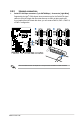
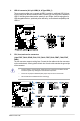
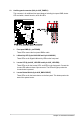
11. System panel connector (20-1 pin PANEL1)
Thisconnectorsupportsseveralchassis-mountedfunctions.
1. System power LED (3-pin PLED)
This3-pinconnectorisforthesystempowerLED.Connectthechassispower
LEDcabletothisconnector.ThesystempowerLEDlightsupwhenyouturnon
thesystempower,andblinkswhenthesystemisinsleepmode.
2. Message LED (2-pin MLED)
This2-pinconnectorisforthemessageLEDcablethatconnectstothefront
messageLED.ThemessageLEDiscontrolledbyHardwaremonitortoindicate
anabnormaleventoccurrence.
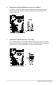
3. System warning speaker (4-pin SPEAKER)
This 4-pin connector is for the chassis-mounted system warning speaker. The
speaker allows you to hear system beeps and warnings.
4. Hard disk drive activity LED (2-pin +HDLED)
This2-pinconnectorisfortheHDDActivityLED.ConnecttheHDDActivityLED
cabletothisconnector.TheIDELEDlightsuporasheswhendataisreadfrom
orwrittentotheHDD.
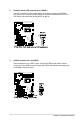
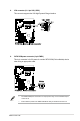
5. Power button/soft-off button (2-pin PWRSW)
This connector is for the system power button. Pressing the power button turns
the system on or puts the system in sleep or soft-off mode depending on the
BIOSsettings.Pressingthepowerswitchformorethanfoursecondswhilethe
system is ON turns the system OFF.
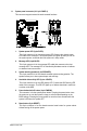
6. Reset button (2-pin RESET)
This 2-pin connector is for the chassis-mounted reset button for system reboot
without turning off the system power.