Motherboard P12R-M Series
E18697 First Edition August 2021 Copyright © 2021 ASUSTeK COMPUTER INC. All Rights Reserved. No part of this manual, including the products and software described in it, may be reproduced, transmitted, transcribed, stored in a retrieval system, or translated into any language in any form or by any means, except documentation kept by the purchaser for backup purposes, without the express written permission of ASUSTeK COMPUTER INC. (“ASUS”).
Contents Safety information...................................................................................................... vii Electrical safety...............................................................................................vii Operation safety..............................................................................................vii P12R-M Series Specifications Summary.................................................................. ix Chapter 1: Product Introduction 1.
Contents 2.6 Jumpers..................................................................................................... 2-23 2.7 Onboard LEDs........................................................................................... 2-29 2.8 Connectors................................................................................................ 2-31 2.8.1 Rear panel connectors............................................................... 2-31 2.8.2 Internal connectors...........................
Contents 4.5 4.4.8 Serial Port Console Redirection................................................. 4-19 4.4.9 Intel TXT Information................................................................. 4-22 4.4.10 SIO Configuration...................................................................... 4-22 4.4.11 PCI Subsystem Settings............................................................ 4-23 4.4.12 USB Configuration..................................................................... 4-27 4.
Contents 5.3 Intel® Rapid Storage Technology enterprise (Windows)......................... 5-7 5.3.1 Creating a RAID set..................................................................... 5-8 5.3.2 Changing a Volume Type.......................................................... 5-10 5.3.3 Deleting a volume...................................................................... 5-11 5.3.4 Preferences................................................................................ 5-12 Chapter 6: 6.
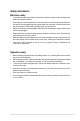
Safety information Electrical safety • To prevent electrical shock hazard, disconnect the power cable from the electrical outlet before relocating the system. • When adding or removing devices to or from the system, ensure that the power cables for the devices are unplugged before the signal cables are connected. If possible, disconnect all power cables from the existing system before you add a device.
Conventions used in this guide To ensure that you perform certain tasks properly, take note of the following symbols used throughout this manual. DANGER/WARNING: Information to prevent injury to yourself when trying to complete a task. CAUTION: Information to prevent damage to the components when trying to complete a task. IMPORTANT: Instructions that you MUST follow to complete a task. NOTE: Tips and additional information to help you complete a task.
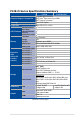
P12R-M Series Specifications Summary Processor Support / System Bus Core Logic Form Factor P12R-M P12R-M/10G-2T 1 x Socket H5 (LGA 1200) Intel® Xeon® E processor (up to 95W) Intel® Pentium™ processor Intel® C252 Chipset Micro ATX, 9.6 in. x 9.6 in. Fan Speed Control Rack Ready ASUS Features (Rack and Pedestal dual use) ASUS Control Center 4 (2 Channels) 1.
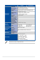
TPM Header PSU Connector Management Header Onboard I/O Connectors USB Connector/ Header Fan Header SMBus Chassis Intruder Front LAN LED Serial Port Header VGA Header M.2 Connector External USB Port VGA Port Rear I/O Connectors RJ-45 Management Solution P12R-M P12R-M/10G-2T 1 24-pin ATX power connector 8-pin ATX 12V power connector Onboard header for optional management card 2 x USB 3.2 Gen 2 (rear), 1 x USB 3.2 Gen 2 (header, 2 ports), 1 x USB 2.
Chapter 1: Product Introduction Product Introduction This chapter describes the motherboard features and the new technologies it supports.
1.1 Welcome! Thank you for buying an ASUS® P12R-M Series motherboard! The motherboard delivers a host of new features and latest technologies, making it another standout in the long line of ASUS quality motherboards! Before you start installing the motherboard and hardware devices on it, check the items in your package with the list below. 1.2 Package contents Check your motherboard package for the following items.
1.3 Serial number label Before requesting support from the ASUS Technical Support team, you must take note of the motherboard's serial number containing 12 characters xxSxxxxxxxxx shown as the figure below. With the correct serial number of the product, ASUS Technical Support team members can then offer a quicker and satisfying solution to your problems. P12R-M xxSxxxxxxxxx P12R-M/10G-2T xxSxxxxxxxxx 1.4 Special features 1.4.
Intel® EM64T The motherboard supports Intel® processors with the Intel® EM64T (Extended Memory 64 Technology). The Intel® EM64T feature allows your computer to run on 64-bit operating systems and access larger amounts of system memory for faster and more efficient computing. DDR4 memory support The motherboard supports DDR4 memory that features faster clock frequencies and higher data transfer rates of 3200 MT/s (million transfers per second). DDR4 offers a lower voltage standard of 1.
Temperature, fan, and voltage monitoring The CPU temperature is monitored to prevent overheating and damage. The system fan rotations per minute (RPM) is monitored for timely failure detection. The chip monitors the voltage levels to ensure stable supply of current for critical components. 1.4.2 Innovative ASUS features ASUS Fan Speed technology The ASUS Fan Speed technology smartly adjusts the fan speeds according to the system loading to ensure quiet, cool, and efficient operation.
1-6 Chapter 1: Product Introduction
Chapter 2: Hardware Information Hardware Information This chapter lists the hardware setup procedures that you have to perform when installing system components. It includes description of the jumpers and connectors on the motherboard.
2.1 Before you proceed Take note of the following precautions before you install motherboard components or change any motherboard settings. 2-2 • Unplug the power cord from the wall socket before touching any component. • Use a grounded wrist strap or touch a safely grounded object or a metal object, such as the power supply case, before handling components to avoid damaging them due to static electricity. • Hold components by the edges to avoid touching the ICs on them.
2.2 Motherboard overview Before you install the motherboard, study the configuration of your chassis to ensure that the motherboard fits into it. To optimize the motherboard features, we highly recommend that you install it in an ATX 2.2 compliant chassis. Ensure to unplug the chassis power cord before installing or removing the motherboard. Failure to do so can cause you physical injury and damage motherboard components! 2.2.
P12R-M/10G-2T Place this side towards the rear of the chassis 2-4 Chapter 2: Hardware Information
2.2.
P12R-M/10G-2T 2-6 Chapter 2: Hardware Information
2.2.4 Layout contents Slots/Sockets Page 1. 2-9 CPU socket 2. DDR4 sockets 2-15 3. PCI Express x16 / PCI Express x8 2-19 Jumpers Page 1. Clear RTC RAM (2-pin CLRTC) 2-23 2. VGA controller setting (3-pin VGA_SW1) 2-24 3. DDR4 Thermal Event jumper (3-pin DIMMTRIP2) 2-24 4. ME firmware force recovery setting (3-pin ME_RCVR1) 2-25 5. Smart Ride Through (SmaRT) setting (3-pin SMART_PSU1) 2-25 6. DMLAN setting (3-pin DM_IP_SEL1) 2-26 7.
Rear panel connectors (P12R-M/10G-2T) Page 1. 2-32 Video Graphics Adapter port 2. RJ-45 port for iKVM 2-32 3. USB 3.2 Gen 2 ports 1 and 2 2-32 4. RJ-45 ports for Intel® LOM X710AT LAN 1-2 2-32 5. HDMI™ port 2-32 6. Q-Code LED 2-32 7. Power-on Button 2-32 Internal connectors Page 1. Serial ATA 6.0 Gbp/s connectors (7-pin SATA6G_1-4; SATA5-6) 2-34 2. Hard disk activity LED connector (4-pin HDLED1) 2-34 3. Serial General Purpose Input/Output connector (6-1 pin SGPIO1) 2-35 4.
2.3 Central Processing Unit (CPU) The motherboard comes with a surface mount LGA1200 socket designed for the Intel® Xeon® E processor (up to 95W) and Intel® Pentium™ processors. • Upon purchase of the motherboard, ensure that the PnP cap is on the socket and the socket contacts are not bent. Contact your retailer immediately if the PnP cap is missing, or if you see any damage to the PnP cap/socket contacts/motherboard components.
2. Press the load lever with your thumb (A), then move it to the right (B) until it is released from the retention tab. Do not remove the PnP cap yet from the CPU socket. Doing so may bend the pins of the socket. Load lever Retention tab 3. Lift the load plate. Load plate 4. Remove the PnP cap from the CPU socket. 5. Position the CPU above the socket, ensuring that the gold triangle mark is on the bottom-left corner of the socket, then fit the CPU notches to the socket's alignment keys.
6. Close the load plate (A), ensuring that the front edge of the load plate slides under the retention lock (B). 7. Push the load lever down and insert it under the retention tab to secure the CPU in the socket. 8. Apply some Thermal Interface Material to the exposed area of the CPU that the heatsink will be in contact with, ensuring that it is evenly spread in a thin layer. Some heatsinks come with preapplied Thermal Interface Material. If so, skip this step.
2.3.2 Installing the CPU heatsink The Intel LGA1200 processor requires a specially designed CPU heatsink to ensure optimum thermal condition and performance. ® • When you buy a boxed Intel® processor, a specially designed CPU heatsink or a CPU heatsink with a CPU fan assembly is included depending on the package. If you buy a CPU separately, ensure that you use only Intel® certified multi‑directional CPU heatsink or CPU heatsink with CPU fan.
3. Connect the CPU fan cable to the connector on the motherboard labeled CPU_FAN1. DO NOT forget to connect the CPU fan connector! Hardware monitoring errors can occur if you fail to plug this connector. 2.3.3 Uninstalling the CPU heatsink and fan To uninstall the CPU heatsink and fan: 1. Disconnect the CPU fan cable from the connector on the motherboard. 2. Rotate each fastener counterclockwise. 3.
2.3.4 Installing the CPU heatsink in rack The Intel® LGA1200 processor requires a specially designed heatsink to ensure optimum thermal condition and performance. • Ensure that you use qualified heatsink assembly only. • Ensure that you have applied the thermal interface material to the top of the CPU before installing the heatsink and fan. 1. Peel off the sticker on the heatsink metal plate and affix the plate to the back of the motherboard, matching the standoffs to the heatsink screw holes. 2.
2.4 System memory 2.4.1 Overview The motherboard comes with four (4) Double Data Rate 4 (DDR4) Dual Inline Memory Modules (DIMM) sockets. A DDR4 module is notched differently from a DDR, DDR2, or DDR3 module. DO NOT install a DDR, DDR2, or DDR3 memory module to the DDR4 slot. The figure illustrates the location of the DDR4 DIMM sockets: 2.4.2 Memory configurations You may install unbuffered DDR4 DIMMs into the DIMM sockets using the memory configurations in this section.
2.4.3 Installing a DIMM Ensure to unplug the power supply before adding or removing DIMMs or other system components. Failure to do so may cause severe damage to both the motherboard and the components. 1. Unlock a DIMM socket by pressing the retaining clips outward. 2. Align a DIMM on the socket such that the notch on the DIMM matches the DIMM slot key on the socket. DIMM notch DIMM slot key Unlocked retaining clip A DIMM is keyed with a notch so that it fits in only one direction.
2.5 Expansion slots In the future, you may need to install expansion cards. The following subsections describe the slots and the expansion cards that they support. Ensure to unplug the power cord before adding or removing expansion cards. Failure to do so may cause you physical injury and damage motherboard components. 2.5.1 Installing an expansion card To install an expansion card: 1.
2.5.
2.5.4 PCI Express x8 slot (x4 link) The onboard PCIEX8_4 provide one x4 Gen4 link to the PCH. These slots support various server class high performance add-on cards. 2.5.5 PCI Express x16 slot (x16 link) The onboard PCIEX16_6 provides one x16 Gen4 link to CPU. This slot supports VGA cards and various server class high performance add-on cards. No.
2.5.6 Installing the Baseboard Management Card Follow the steps below to install an optional ASMB10 Management Card on your motherboard. The motherboard illustration is for reference only. The motherboard layout and appearance may vary depending on the model, but the installation steps remain the same. 1. Locate the Baseboard Management Card header on the motherboard. 2. Orient and press the Management Card in place.
2.5.7 Installing an M.2 module You may install an M.2 card (supports up to 2280) to the onboard M.2 slot on the motherboard. This connector supports type 2242 / 2260 / 2280 devices on PCIe Gen 3 x4 interface. • The M.2 (NGFF) device is purchased separately. • The motherboard illustration is for reference only. The motherboard layout and appearance may vary depending on the model, but the installation steps remain the same. 1. Locate the M.2 slot (M.2_1(SOCKET3)) on the motherboard. 2.
2.5.8 (optional) Installing the PFR module The optional PFR module will come pre-installed on your system and is connected to the PFR module connector on your motherboard. • The illustration below is for reference only. • For more information or assistance, please refer to www.asus.com. 1. Locate the PFR module connector on your motherboard. 2. Align and connect the PFR module to the PFR module connector. 3.
2.6 Jumpers The motherboard illustration is for reference only. The motherboard layout and appearance may vary depending on the model, but the locations for these jumpers/LEDs/connectors remain the same. 1. Clear RTC RAM (2-pin CLRTC) This jumper allows you to clear the CMOS memory system setup parameters by erasing the CMOS Real Time Clock (RTC) RAM data. The onboard button cell battery powers the RAM data in CMOS, which include system setup information such as system passwords. To erase the RTC RAM: 1.
2. VGA controller setting (3-pin VGA_SW1) This jumper allows you to enable or disable the onboard VGA controller. Set to pins 1–2 to activate the VGA feature. 3. DDR4 Thermal Event jumper (3-pin DIMMTRIP2) Set to pins 1-2 to enable DDR4 DIMM thermal sensing event.
4. ME firmware force recovery setting (3-pin ME_RCVR1) This jumper allows you to force Intel Management Engine (ME) boot from recovery mode when ME become corrupted. 5. Smart Ride Through (SmaRT) setting (3-pin SMART_PSU1) This jumper allows you to enable or disable the Smart Ride Through (SmaRT) function. This feature is disabled by default. Set to pins 1-2 to enable it. When enabled, SmaRT allows uninterrupted operation of the system during an AC loss event.
6. DMLAN setting (3-pin DM_IP_SEL1) This jumper allows you to select the DMLAN setting. Set to pins 2-3 to force the DMLAN IP to static mode (IP=10.10.10.10, submask=255.255.255.0). 7. SATADOM power setting (3-pin DOM_PWR1) This jumper allows SATA56 to support SATADOM which do not need external power connections. Set to pins 2-3 to activate the SATA56 support feature.
8. CPU PCIE configuration setting (4-pin CFG5-6) These jumpers allow you to configure the speed at which PCIEX16_6 will run at. Refer to the table below for the different jumper configurations.
9. PCIe SMBus Switcher setting (3-pin SMB_SW1) This jumper allows toggle whether the SMBUS signal comes from BMC or PCH.
2.7 Onboard LEDs The motherboard illustration is for reference only. The motherboard layout and appearance may vary depending on the model, but the locations for these jumpers/LEDs/connectors remain the same. 1. Standby Power LED (SBPWR1) The motherboard comes with a standby power LED. The green LED lights up to indicate that the system is ON, in S5 mode. This is a reminder that you should shut down the system and unplug the power cable before removing or plugging in any motherboard component.
3. Location LED (LOCLED1) This onboard LED lights up when the Location button on the server is pressed or when triggered by a system management software. The Location LED helps visually locate and quickly identify the server in error on a server rack. 4. Message LED (MLED1) This onboard LED lights up to indicate that there is a temperature warning or a BMC event log is generated.
2.8 Connectors 2.8.1 Rear panel connectors P12R-M 1. Video Graphics Adapter port. This port is for a VGA monitor or other VGA-compatible devices. 2. RJ-45 ports for Intel® I210 LAN 1-2. These ports allows Gigabit connection to a Local Area Network (LAN) through a network hub. Refer to the table below for the LAN port LED indications. 3. RJ-45 port for iKVM. This RJ-45 port functions only when you enable ASMB10 Management card. 4. USB 3.2 Gen 2 ports 1 and 2.
P12R-M/10G-2T 1. Video Graphics Adapter port. This port is for a VGA monitor or other VGA-compatible devices. 2. RJ-45 port for iKVM. This RJ-45 port functions only when you enable ASMB10 Management card. 3. USB 3.2 Gen 2 ports 1 and 2. These two 4-pin USB ports are available for connecting USB 3.2 Gen 2 devices. 4. RJ-45 ports for Intel® LOM X710AT LAN 1-2. These ports allows Gigabit connection to a Local Area Network (LAN) through a network hub.
Intel® I210 LAN port LED indications Activity/Link LED Status Description Speed LED Status ACT/LINK SPEED LED LED Description OFF No link OFF 10 Mbps connection GREEN Linked ORANGE 100 Mbps connection BLINKING Data activity GREEN 1 Gbps connection ACT/LINK SPEED LED LED Intel® LOM X710AT LAN port LED indications Activity/Link LED Status Description ACT/LINK SPEED LED LED Speed LED Status Description OFF No link OFF 100 Mbps connection GREEN Linked ORANGE 1 Gbps connection BLINK
2.8.2 1. Internal connectors Serial ATA 6.0 Gbp/s connectors (7-pin SATA6G_1-4; SATA5-6) Supported by the Intel® C252 chipset, these connectors are for the Serial ATA signal cables for Serial ATA hard disk drives that allows up to 6Gb/s of data transfer rate. If you installed Serial ATA hard disk drives, you can create a RAID 0, RAID 1, RAID 10, or RAID 5 configuration. The actual data transfer rate depends on the speed of Serial ATA hard disks installed. 2.
3. Serial General Purpose Input/Output connector (6-1 pin SGPIO1) The SGPIO 1 connector is used for the Intel Rapid Storage Technology Enterprise SGPIO interface that controls the LED pattern generation, device information, and general purpose data. DO NOT connect a 1394 cable to the USB connectors. Doing so will damage the motherboard! 4. USB 2.0 connectors (10-1 pin USB67) This connector allows you to connect a USB 2.0 module for additional USB 2.0 front or rear panel ports.
5. USB 3.2 Gen 2 connector (20-1 pin USB3_34) This connector allows you to connect a USB 3.2 Gen 2 module for additional USB 3.2 Gen 2 front or rear panel ports. The USB 3.2 Gen 2 connector provides data transfer speeds of up to 10 Gb/s. The USB 3.2 Gen 2 module is purchased separately. The plugged USB 3.2 Gen 2 device may run on xHCI or EHCI mode depending on the operating system’s setting. 6. VGA connector (16-pin VGA_HDR1) This connector supports the VGA High Dynamic-Range interface.
7. Trusted Platform Module connector (14-1 pin TPM1) This connector supports a Trusted Platform Module (TPM) system, which can securely store keys, digital certificates, passwords, and data. A TPM system also helps enhance network security, protects digital identities, and ensures platform integrity. 8. Fan connectors (4-pin CPU_FAN1, FRNT_FAN1-4, REAR_FAN1) The fan connectors support cooling fans.
9. Serial port connector (10-1 pin COM1) These connectors are for the serial (COM) ports. Connect the serial port module cable to the connector, then install the module to a slot opening at the back of the system chassis. The COM module is purchased separately. 10. Power Supply SMBus connector (5-pin PSUSMB1) This connector allows you to connect SMBus (System Management Bus) to the PSU (power supply unit) to read PSU information.
11. ATX power connectors (24-pin EATXPWR1, 8-pin EATX12V1) These connectors are for the ATX power supply plugs. The power supply plugs are designed to fit these connectors in only one orientation. Find the proper orientation and push down firmly until the connectors completely fit. • DO NOT forget to connect the 24-pin and the 8-pin power plugs; otherwise, the system will not boot up.
12. System panel connector (20-1 pin PANEL1) This connector supports several chassis-mounted functions. • System power LED (3-pin PLED) This 3-pin connector is for the system power LED. Connect the chassis power LED cable to this connector. The system power LED lights up when you turn on the system power, and blinks when the system is in sleep mode. • Message LED (2-pin MLED) This 2-pin connector is for the message LED cable that connects to the front message LED.
13. Auxiliary panel connectors (20-2 pin AUX_PANEL1; 20-pin AUX_PANEL2) These connectors are for additional front panel features including front panel SMB, locator LED and switch, chassis intrusion, and LAN LEDs. • Front panel SMB (6-1 pin FPSMB) This 6-1 pin connector is for the front panel SMBus cable. • LAN activity LED (2-pin LAN1_LED, LAN2_LED) This 2-pin connector is for the Gigabit LAN activity LEDs on the front panel.
14. Chassis intrusion connector (2-pin INTRUSION) This connector is for a chassis-mounted intrusion detection sensor or switch. Connect one end of the chassis intrusion sensor or switch cable to this connector. The chassis intrusion sensor or switch sends a high-level signal to this connector when a chassis component is removed or replaced. The signal is then generated as a chassis intrusion event. By default, the pin labeled “Chassis Signal” and “Ground” are shorted with a jumper cap.
16. Thermal sensor cable connector (3-pin TR1) This connector allows you to connect a thermal sensor cable that is used for monitoring temperature. Connect the thermal sensor cable to the connector and place its probe to the device that you want to monitor. 17. VPP_I2C connector (10-1 pin VPP_I2C1) The VPP_I2C connector is used for the storage backplane with sensor readings.
2-44 Chapter 2: Hardware Information
Powering Up This chapter describes the power up sequence, and ways of shutting down the system.
3.1 Starting up for the first time 1. After making all the connections, replace the system case cover. 2. Be sure that all switches are off. 3. Connect the power cord to the power connector at the back of the system chassis. 4. Connect the power cord to a power outlet that is equipped with a surge protector. 5. Turn on the devices in the following order: 6. a. Monitor b. External storage devices (starting with the last device on the chain) c.
3.2 Powering off the computer 3.2.1 Using the OS shut down function Using Windows® Server 2019: 1. Press ++. 2. Click on the Power icon on the lower right side of the screen. 3. Select Shut down. 4. In the Shutdown Event Tracker, select the Other (Planned) option in the selection lists. Otherwise, select the option that best describes why you want to shut down the computer. 5. Click Continue. 3.2.
BIOS Setup This chapter tells how to change the system settings through the BIOS Setup menus. Detailed descriptions of the BIOS parameters are also provided.
4.1 Managing and updating your BIOS The following utilities allow you to manage and update the motherboard Basic Input/Output System (BIOS) setup: 1. ASUS CrashFree BIOS 3 To recover the BIOS using a bootable USB flash disk drive when the BIOS file fails or gets corrupted. 2. ASUS EzFlash Updates the BIOS using a USB flash disk. 3. BUPDATER Updates the BIOS in DOS mode using a bootable USB flash disk drive. Refer to the corresponding sections for details on these utilities.
4.1.2 ASUS EzFlash Utility The ASUS EzFlash Utility feature allows you to update the BIOS using a USB flash disk without having to use a DOS‑based utility. Download the latest BIOS from the ASUS website at www.asus.com before using this utility. The succeeding BIOS screens are for reference only. The actual BIOS screen displays may not be the same as shown. To update the BIOS using EzFlash Utility: 1. Insert the USB flash disk that contains the latest BIOS file to the USB port. 2.
• This function can support devices such as a USB flash disk with FAT 32/16 format and single partition only. • DO NOT shut down or reset the system while updating the BIOS to prevent system boot failure! Ensure to load the BIOS default settings to ensure system compatibility and stability. Press and select Yes to load the BIOS default settings. 4.1.3 BUPDATER utility The succeeding BIOS screens are for reference only. The actual BIOS screen displays may not be the same as shown.
The utility verifies the file, then starts updating the BIOS file. ASUSTek. EzFlash Utility Current Platform Platform : P12R-M Version : 0201 Build date: 04/13/2021 Start Programming Flash. New Platform Platform : P12R-M Version : 0207 Build date: 06/25/2021 DO NOT SHUTDOWN THE SYSTEM!!! Write 75% DO NOT shut down or reset the system while updating the BIOS to prevent system boot failure! The utility returns to the DOS prompt after the BIOS update process is completed. 4.
4.2 BIOS setup program This motherboard supports a programmable firmware chip that you can update using the provided utility described in section 4.1 Managing and updating your BIOS. Use the BIOS Setup program when you are installing a motherboard, reconfiguring your system, or prompted to “Run Setup.” This section explains how to configure your system using this utility. Even if you are not prompted to use the Setup program, you can change the configuration of your computer in the future.
4.2.1 BIOS menu screen Menu items Menu bar Configuration fields General help Navigation keys 4.2.
4.2.3 Menu items The highlighted item on the menu bar displays the specific items for that menu. For example, selecting Main shows the Main menu items. The other items (Advanced, Chipset, Security, Boot, Monitor, Tool, Event Logs, Server Mgmt, and Exit) on the menu bar have their respective menu items. 4.2.4 Submenu items A solid triangle before each item on any menu screen means that the item has a submenu. To display the submenu, select the item then press . 4.2.
4.3 Main menu When you enter the BIOS Setup program, the Main menu screen appears. The Main menu provides you an overview of the basic system information, and allows you to set the system date, time, and language. Navigate to the second page of the screen to see the rest of items in this menu by pressing the Up or Down arrow keys. To quickly go to the last item of the second page, press the Page Down button. Press the Page Up button to go back to the first item in the first page. 4.3.
4.4 Advanced menu The Advanced menu items allow you to change the settings for the CPU and other system devices. Take caution when changing the settings of the Advanced menu items. Incorrect field values can cause the system to malfunction.
4.4.1 CPU Configuration CPU Flex Ratio Override [Disabled] Allows you to enable or disable CPU Flex Ratio Override. Configuration options: [Disabled] [Enabled] The following item appears only when CPU Flex Ratio Override is set to [Enabled]. CPU Flex Ratio Settings [37] Allows you to set the CPU Flex Ratio. This value must be between the Max Efficiency Ratio (LFM) and the Maximum non-turbo ratio set by the Hardware (HFW).
AVX [Enabled] Allows you to enable or disable the AVX 2/3 Instructions. This is applicable for Big Core only. Configuration options: [Disabled] [Enabled] AVX3 [Enabled] Allows you to enable or disable the AVX 3 Instructions. This is applicable for Big Core only. Configuration options: [Disabled] [Enabled] Active Processor Cores [All] Allows you to set the number of cores to enable in each processor package.
Race To Halt (RTH) [Enabled] Allows you to enable or disable Race To Halt feature. RTH dynamically increases the CPU frequency to quickly enter the package C-State and reduce the overall power. RTH is controlled through MSR 1FC bit 20. Configuration options: [Disabled] [Enabled] Intel(R) Speed Shift Technology [Native Mode] Allows you to enable or disable Intel(R) Speed Shift Technology support. Enabling will expose the CPPC v2 interface to allow for hardware controlled P-states.
The following items appears only when C-States is set to [Enabled]. Enhanced C-States [Enabled] Allows you to enable or disable C11E. Enable this item to allow the CPU to switch to minimum speed when all cores enter C-State. Configuration options: [Disabled] [Enabled] C-State Auto Demotion [C1] This item allows you to configure the C-state auto demotion. Configuration options: [Disabled] [C1] C-State Un-demotion [C1] This item allows you to configure the C-state Un-demotion.
4.4.3 Server ME Configuration Displays the Server ME Technology parameters on your system. Scroll using / keys to see more items.
4.4.4 System Event Log Allows you to view the System Event Main Screen and RAS features enabling. System Errors [Disabled] Allows you to enable or disable system error setup options. Configuration options: [Disabled] [Enabled] The following items appear only when System Errors is set to [Enabled]. Whea Driver Support [Disabled] Allows you to enable or disable Whea Driver Support. This option may not be effective with some OS.
The following item appears only when PCH Error Enable is set to [Yes]. PCI/PCI Error Enabling: Press to view or change PCH errors enabling options. PCI-Ex Error Enable [No] Configuration options: [No] [Yes] Fatal Error Enable [Enabled] Allows you to enable and escalate fatal errors to error pins. Configuration options: [Disable Link] [Enabled] Uncorrected Error Enable [Enabled] Allows you to enable and escalate Uncorrectable/Recoverable errors to error pins.
4.4.6 Redfish Host Interface Settings Redfish [Disabled] Allows you to enable or disable Redfish. Configuration options: [Disabled] [Enabled] The following items appear only when Redfish is set to [Enabled]. Authentication mode [Basic Authentication] Allows you to select the authentication mode. Configuration options: [Basic Authentication] [Session Authentication] Redfish BMC Settings IP address Enter the IP address. IP Mask address Enter the IP Mask address. IP Port Enter the IP Port. 4.4.
P12R-M/10G-2T Onboard X710 LAN Configuration Intel X710 LAN1-2 LAN Enable [Enabled] Allows you to enable or disable the Intel LAN. Configuration options: [Disabled] [Enabled] 4.4.8 Serial Port Console Redirection COM1 Console Redirection [Disabled] Allows you to enable or disable the console redirection feature. Configuration options: [Disabled] [Enabled] The following item appears only when Console Redirection is set to [Enabled].
Terminal Type [ANSI] Allows you to set the terminal type. [VT100] ASCII char set. [VT100+] Extends VT100 to support color, function keys, etc. [VT-UTF8] Uses UTF8 encoding to map Unicode chars onto 1 or more bytes. [ANSI] Extended ASCII char set. Bits per second [115200] Selects serial port transmission speed. The speed must be matched on the other side. Long or noisy lines may require lower speeds.
Legacy Console Redirection Settings Legacy Console Redirection Port [COM1] Allows you to select a COM port to display redirection of Legacy OS and Legacy OPROM Messages. Configuration options: [COM1] [COM2 (Disabled)] Resolution [80x24] Allows you to select a the number of rows and columns in supported redirection. Configuration options: [80x24] [80x25] Redirect After POST [Always Enable] Allows you to select the redirection after POST.
4.4.9 Intel TXT Information You may view the Intel TXT information in this menu. 4.4.10 SIO Configuration Logical Devices state on the left side of the control, reflects the current Logical Device state. Changes made during Setup Session will be shown after you restart the system. [*Active*] Serial Port 1 / [*Active*] Serial Port 2 Allows you to view and set basic properties of the SIO Logical device. Like IO Base, IRQ Range, DMA Channel, and Device Mode.
The following item appears only when Use This Device is set to [Enabled]. Disabling SIO Logical Devices may have unwanted side effects. PROCEED WITH CAUTION. Possible: [Use Automatic Settings] Allows the user to change the device resource settings. New settings will be reflected no this setup page after system restarts.
PERR# Generation [Disabled] Allows you to enable or disable PCI Device to Generate PERR#. Configuration options: [Disabled] [Enabled] SERR# Generation [Disabled] Allows you to enable or disable PCI Device to Generate SERR#. Configuration options: [Disabled] [Enabled] Above 4G Decoding [Enabled] Allows you to enable or disable 64-bit capable devices to be decoded in above 4G address space. It only works if the system supports 64-bit PCI decoding.
Maximum Payload [Auto] Allows you to set Maximum Payload of PCI Express Device or allow System BIOS to select the value. Configuration options: [Auto] [128 Bytes] [256 Bytes] [512 Bytes] [1024 Bytes] [2048 Bytes] [4096 Bytes] Maximum Read Request [Auto] Allows you to set Maximum Read Request Size of PCI Express Device or allow System BIOS to select the value.
ARI Forwarding [Disabled] If supported by hardware and set to [Enabled], the Downstream Port disables its traditional Device Number field being 0 enforcement when turning a Type1 Configuration Request into a Type0 Configuration Request, permitting access to Extended Functions in an ARI Device immediately below the Port.
Compliance SOS [Disabled] If supported by hardware and set to [Enabled], this will force LTSSM to send SKP Ordered Sets between sequences when sending Compliance Pattern or Modified Compliance Pattern. Configuration options: [Disabled] [Enabled] Hardware Autonomous Width [Enabled] If supported by hardware and set to [Disabled], this will disable the hardware’s ability to change link width except width size reduction for the purpose of correcting unstable link operation.
USB Mass Storage Driver Support [Enabled] Allows you to enable or disable USB Mass Storage driver support. Configuration options: [Disabled] [Enabled] Port 60/64 Emulation [Enabled] Allows you to enable or disable Port 60/64 Emulation. Configuration options: [Disabled] [Enabled] USB hardware delays and time-outs USB transfer time-out [20 sec] Allows you to set the time-out value for Control, Bulk, and Interrupt transfers.
The following items appear only when Network Stack is set to [Enabled]. Ipv4 PXE Support [Disabled] Enables or disables the Ipv4 PXE Boot Support. If disabled, Ipv4 PXE boot option will not be created. Configuration options: [Disabled] [Enabled] Ipv4 HTTP Support [Disabled] Enables or disables the Ipv4 HTTP Boot Support. If disabled, Ipv4 PXE boot option will not be created. Configuration options: [Disabled] [Enabled] Ipv6 PXE Support [Disabled] Enables or disables the Ipv6 PXE Boot Support.
The following items appear only when Launch CSM is set to [Enabled]. GateA20 Active [Upon Request] This allows you to set the GA20 option. [Upon Request] GA20 can be disabled using BIOS services. [Always] Do not allow disabling GA20; this option is useful when any RT code is executed above 1MB. Interrupt 19 Capture [Immediate] Allows you to select the BIOS reaction on INT19 trapping by Option ROM. [Immediate] Execute the trap right away. [Postponed] Execute the trap during legacy boot.
4.4.15 NVMe Configuration You may view the NVMe controller and Drive information if an NVMe device is connected. 4.4.16 APM Configuration This page will allow you to configure the Advance Power Management (APM) settings. Restore AC Power Loss [Last State] When set to [Power Off], the system goes into off state after an AC power loss. When set to [Power On], the system will reboot after an AC power loss.
4.4.17 Third-party UEFI driver configurations Additional configuration options for third-party UEFI drivers installed to the system will appear in the section marked in red in the screenshot below.
4.5 Chipset menu The Chipset menu allows you to change the platform settings. Take caution when changing the settings of the Chipset menu items. Incorrect field values can cause the system to malfunction. 4.5.1 System Agent (SA) Configuration Memory Configuration Maximum Memory Frequency [Auto] Allows you to select the maximum memory frequency setting.
ECC Support [Enabled] Allows you to enable or disable the DDR Ecc support. Configuration options: [Disabled] [Enabled] DDR Speed Control [Auto] Allows you to set DDR Frequency and Gear1 / Gear2 control for all SAGV points. Configuration options: [Auto] [Manual] Memory Scrambler [Enabled] Allows you to enable or disable Memory Scrambler support. Configuration options: [Disabled] [Enabled] Fast Boot [Disabled] Allows you to enable or disable fast path thru the MRC.
IOP VTD Enable [Enabled] Allows you to enable or disable IOP VTD. Configuration options: [Disabled] [Enabled] CRID Support [Disabled] Allows you to enable or disable SA CRID and TCSS CRID control for Intel SIPP. Configuration options: [Disabled] [Enabled] Above 4G Decoding [Enabled] Allows you to enable or disable 64-bit capable devices to be decoded in above 4G address space. It only works if the system supports 64-bit PCI decoding. Configuration options: [Disabled] [Enabled] 4.5.
SATA 1 Port 1 [Enabled] Allows you to enable or disable the SATA port. Configuration options: [Disabled] [Enabled] SATA6G_1 Hot Plug [Disabled] Allows you to enable or disable this port as hot pluggable. Configuration options: [Disabled] [Enabled] Spin Up Device [Disabled] Allows you to enable or disable Spin Up Device. If enabled for any of the ports, Staggered Spin Up will be performed and only the drives which have this option enabled will spin up at boot. Otherwise all drives spin up at boot.
SATA Device Type [Hard Disk Drive] Allows you to identify the SATA port is connected to a solid state drive or a hard disk drive Configuration options: [Hard Disk Drive] [Solid State Drive] SATA 4 Port 1 [Enabled] Allows you to enable or disable the SATA port. Configuration options: [Disabled] [Enabled] SATA6G_4 Hot Plug [Disabled] Allows you to enable or disable this port as hot pluggable. Configuration options: [Disabled] [Enabled] Spin Up Device [Disabled] Allows you to enable or disable Spin Up Device.
Spin Up Device [Disabled] Allows you to enable or disable Spin Up Device. If enabled for any of the ports, Staggered Spin Up will be performed and only the drives which have this option enabled will spin up at boot. Otherwise all drives spin up at boot.
4.6 Security menu This menu allows a new password to be created or a current password to be changed. The menu also enables or disables the Secure Boot state and lets the user configure the System Mode state. Administrator Password To set an administrator password: 1. Select the Administrator Password item and press . 2. From the Create New Password box, key in a password, then press . 3. Confirm the password when prompted. To change an administrator password: 1.
User Password To set a user password: 1. Select the User Password item and press . 2. From the Create New Password box, key in a password, then press . 3. Confirm the password when prompted. To change a user password: 1. Select the User Password item and press . 2. From the Enter Current Password box, key in the current password, then press . 3. From the Create New Password box, key in a new password, then press . 4. Confirm the password when prompted.
The following items are available only when Secure Boot Mode is set to [Custom]. Install Default Secure Boot Keys This option will load the default secure boot keys, including the PK (Platform key), KEK (keyexchange key), db (signature database), and dbx (revoked signature database). All the secure boot keys states will change from unloaded to loaded. Save changes and reset the system for the changes to take effect.
Clear Secure Boot Keys This option will delete all previously applied secure boot keys, including the PK (Platform key), KEK (key-exchange key), db (signature database), and dbx (revoked signature database). All the secure boot keys states will change from unloaded to loaded. Save changes and reset the system for the changes to take effect.
4.7 Boot menu The Boot menu items allow you to change the system boot options. Setup Prompt Timeout [1] Allows you to set the number of seconds that the firmware waits before initiating the original default boot selection. 65535(OxFFFF) means indefinite waiting. Use the <+> or <-> to adjust the value. Bootup NumLock State [Off] Allows you to select the power-on state for the NumLock. Configuration options: [Off] [On] Boot Logo Display [Disabled] [Disabled] Hide the logo during POST.
Boot Option Priorities These items specify the boot device priority sequence from the available devices. The number of device items that appears on the screen depends on the number of devices installed in the system. • To select the boot device during system startup, press when ASUS Logo appears. • To access Windows OS in Safe Mode, please press after POST.
4.8 Monitor menu This menu displays the system temperature, fan speed, and power status. You can also change the fan settings in this menu. Fan Speed Control [Auto Mode] Allows you to select the power-on state for the NumLock. Configuration options: [Auto Mode] [Full Speed Mode] [Manual Speed Mode] The following items appear only when Fan Speed Control is set to [Manual Speed Mode]. REAR_FAN1 / CPU_FAN1 / FRNT_FAN1-4 Duty% [50] Allows you to set the desired POST Report waiting time from 1 to 10 seconds.
4.9 Tool menu Start ASUS EzFlash Allows you to run ASUS EzFlash BIOS ROM Utility when you press . Refer to the ASUS EzFlash Utility section for details. ASUS SMBIOS Viewer Allows you to start ASUS SMBIOS Viewer when you press .
4.10 Event Logs menu The Event Logs menu items allow you to change the event log settings and view the system event logs.
4.10.1 Change Smbios Event Log Settings Press to change the Smbios Event Log configuration. All values changed here do not take effect until computer is restarted. Enabling/Disabling Options Smbios Event Log [Enabled] Change this to enable or disable all features of Smbios Event Logging during boot. Configuration options: [Disabled] [Enabled] The following items appear only when Smbios Event Log is set to [Enabled].
The following item appears only when Log EFI Status Code is set to [Enabled]. Convert EFI Status Codes to Standard Smbios Type [Disabled] This option allows you to enable or disable converting of EFI Status Codes to Standard Smbios Type (Not all may be translated). Configuration options: [Disabled] [Enabled] 4.10.2 View Smbios Event Log Press to view all smbios event logs.
4.11 Server Mgmt menu BMC Support [Enabled] This item allows you to enable or disable interfaces to communicate with BMC. Configuration options: [Disabled] [Enabled] The following items appear only when BMC Support is set to [Enabled]. OS Watchdog Timer [Disabled] This item allows you to start a BIOS timer which can only be shut off by Management Software after the OS loads. Configuration options: [Disabled] [Enabled] The following items are configurable only when OS Watchdog Timer is set to [Enabled].
BMC init phase [PEI phase] Allows you to set BMC init phase. Configuration options: [PEI phase] [BDS phase] 4.11.1 System Event Log Allows you to change the SEL event log configuration. Enabling/Disabling Options SEL Components [Enabled] Allows you to enable or disable event logging for error/progress codes during boot. Configuration options: [Disabled] [Enabled] • The following items are configurable only when SEL Components is set to [Enabled].
4.11.2 View FRU information Press to view FRU information. 4.11.3 Bmc self test log Allows you to change the SEL event log configuration. Erase Log [Yes, On every reset] Choose options for erasing Smbios Event Log. Erasing is done prior to any logging activation during reset. Configuration options: [No] [Yes, On every reset] When Log is Full [Clear Log] Allows you to choose options for reactions to a full Smbios Event Log.
4.11.4 BMC network configuration The sub-items in this configuration allow you to configure the BMC network parameters. Navigate to the second page of the screen to see the rest of items in this menu by pressing the Up or Down arrow keys. To quickly go to the last item of the second page, press the Page Down button. Press the Page Up button to go back to the first item in the first page.
Router MAC Address Allows you to set the router MAC address. Configure IPV6 support Lan channel 1 / Lan channel 2 IPV6 support [Enabled] Allows you to enable or disable IPV6 support. Configuration options: [Enabled] [Disabled] The following items appear only when IPV6 support is set to [Enabled]. Configuration Address source [Unspecified] Allows you to set the LAN channel parameters statically or dynamically (by BIOS or by BMC).
4.12 Exit menu The Exit menu items allow you to save or discard your changes to the BIOS items. Pressing does not immediately exit this menu. Select one of the options from this menu or from the legend bar to exit. Save Changes and Reset Reset system after saving the changes. Discard Changes and Reset Reset system setup without saving any changes. Load Optimized Defaults Restore/load default values for all the setup options. Boot Override These items displays the available devices.
4-56 Chapter 4: BIOS Setup
RAID Configuration This chapter provides instructions for setting up, creating, and configuring RAID sets using the available utilities.
5.1 Setting up RAID The motherboard supports the Intel® Rapid Storage Technology enterprise Option ROM Utility with RAID 0, RAID 1, RAID 10, and RAID 5 support (for Windows OS and Linux). 5.1.1 RAID definitions RAID 0 (Data striping) optimizes two identical hard disk drives to read and write data in parallel, interleaved stacks. Two hard disks perform the same work as a single drive but at a sustained data transfer rate, double that of a single disk alone, thus improving data access and storage.
5.1.2 Installing hard disk drives The motherboard supports Serial ATA for RAID set configuration. For optimal performance, install identical drives of the same model and capacity when creating a disk array. To install the SATA hard disks for RAID configuration: 1. Install the SATA hard disks into the drive bays following the instructions in the system user guide. 2. Connect a SATA signal cable to the signal connector at the back of each drive and to the SATA connector on the motherboard. 3.
5.2 Intel® Virtual Raid on CPU in BIOS This feature allows you to do CPU RAID functions with Intel® CPU RSTe. 1. Enter the BIOS Setup during POST. 2. Go to the Advanced menu > Intel(R) VROC SATA Controller then press to display the Intel® Virtual Raid on CPU menu. Refer to Chapter 4 for details on entering and navigating through the BIOS Setup.
5.2.1 Creating a RAID set To create a RAID set: 1. From the Intel® Virtual Raid on CPU menu, select Create RAID Volume and press . The following screen appears: 2. When the Name item is selected, enter a name for the RAID set and press . 3. When the RAID Level item is selected, press to select the RAID level to create, and then press . 4. Under Select Disks, press and select X for the disks you want to include in the RAID set. 5.
5.2.2 Deleting a RAID set Be cautious when deleting a RAID set. You will lose all data on the hard disk drives when you delete a RAID set. To delete a RAID set: 5-6 1. From the Intel® Virtual Raid on CPU menu, select the RAID volume you want to delete and press . The following screen appears: 2. When the Delete item is selected, press , then select Yes to delete the RAID volume and return to the Intel® Virtual Raid on CPU menu, or select No to cancel.
5.3 Intel® Rapid Storage Technology enterprise (Windows) The Intel® Rapid Storage Technology enterprise allows you to create RAID 0, RAID 1, RAID 10 (RAID 1+0), and RAID 5 set(s) from Serial ATA hard disk drives that are connected to the Serial ATA connectors supported by the Southbridge. You need to manually install the Intel® Rapid Storage Technology enterprise utility on a Windows® operating system. Please refer to the installation instructions in Chapter 6.
5.3.1 Creating a RAID set To create a RAID set: 5-8 1. From the utility main menu, select Create Volume and select volume type. 2. Click Next. 3. Enter a name for the RAID set, then select the array disks. 4. Select Volume Size tab, you can drag the bar to decide the volume size. 5. Click Next. • If you do not want to keep the data on one of the selected disks, select NO when prompted. • If you want to Enable volume write-back cache or Initialize volume, click Advanced.
6. Confirm the volume creation, than click Create Volume to continue. This process could take a while depending on the number and size of the disks. You can continue using other applications during this time. 7. Wait until the process is completed, then click OK when prompted. You still need to partition your new volume using Windows Disk Management before adding any data. The RAID set is displayed in the Volumes list and you can change the settings in Volume Properties.
5.3.2 Changing a Volume Type To change the volume type in Volume Properties: 1. Click the SATA array items you want to change in Volumes field. 2. From the Volume Properties field, select Type:RAID 1 Change type. 3. You can change the Name, Select the new volume type, and Select additional disks to include in the new volume if needed. 4. Select the Data stripe size for the RAID array (for RAID 0, 10 and 5 only), and click OK. The available stripe size values range from 4 KB to 128 KB.
5.3.3 Deleting a volume Be cautious when deleting a volume. You will lose all data on the hard disk drives. Before you proceed, ensure that you back up all your important data from your hard drives. To delete a volume: 1. From the utility main menu, select the volume (exp. Volume_0000) in Volumes field you want to delete. 2. Select Delete volume in Volume Properties field. The following screen appears. 3.
5.3.4 Preferences System Preferences Allow you to set to show the notification area icon and show system information, warning, or errors here.
Driver Installation This chapter provides the instructions for installing the necessary drivers for different system components in both Linux® and Windows® Operating Systems.
6.1 RAID driver installation After creating the RAID sets for your server system, you are now ready to install an operating system to the independent hard disk drive or bootable array. This part provides the instructions on how to install the RAID controller drivers during OS installation. 6.1.1 Creating a USB flash drive with RAID drive When installing Windows® Server OS, you can load the RAID driver from a USB flash drive.
3. Click Load Driver. 4. A message appears reminding you to insert the installation media containing the driver of the RAID controller driver (the installation media can be a CD, DVD, or USB flash drive). • If you have only one optical drive installed in your system, eject the Windows OS installation disc and replace with the motherboard Support DVD into the optical drive. • Or you may connect a USB flash drive containing the RAID controller driver. Click Browse to continue. 5.
7. When the system finishes loading the RAID driver, • Replace the motherboard Support DVD with the Windows Server installation disc. • Remove the USB flash drive. Select the drive to install Windows and click Next. 8. 6-4 Setup then proceeds with the OS installation. Follow the onscreen instructions to continue.
6.2 Running the Support DVD The support DVD that is bundled with your motherboard contains drivers, management applications, and utilities that you can install to maximize the features of your motherboard. The contents of the support DVD are subject to change at any time without notice. Visit the ASUS website (www.asus.com) for the latest updates on software and utilities. The main screen of the Support DVD contains the following tabs: 1.
6-6 Chapter 6: Driver Installation
Appendix This appendix includes additional information that you may refer to when configuring the motherboard.
P12R-M Series block diagram A-2 Appendix
Q-Code table Action PHASE POST CODE TYPE DESCRIPTION 0x1 Progress First post code 0x2 Progress Load BSP microcode 0x3 Progress Perform early platform Initialization 0x4 Progress Set cache as ram for PEI phase 0x5 Progress Establish Stack 0x6 Progress CPU Early Initialization 0x10 Progress PEI Core Entry 0x11 Progress PEI cache as ram CPU initial 0x15 Progress NB Initialization before installed memory 0x19 Progress SB Initialization before installed memory 0xB0 MRC Progres
Action PHASE POST CODE TYPE DESCRIPTION 0x90 Progress BDS started 0x91 Progress Connect device event 0x92 Progress PCI Bus Enumeration 0x93 Progress PCI Bus Enumeration 0x94 Progress PCI Bus Enumeration 0x95 Progress PCI Bus Enumeration 0x96 Progress PCI Bus Enumeration 0x97 Progress Console outout connect event 0x98 Progress Console input connect event 0x99 Progress AMI Super IO start 0x9A Progress AMI USB Driver Initialization 0x9B Progress AMI USB Driver Initializa
Notices Federal Communications Commission Statement This device complies with Part 15 of the FCC Rules. Operation is subject to the following two conditions: • This device may not cause harmful interference, and • This device must accept any interference received including interference that may cause undesired operation. This equipment has been tested and found to comply with the limits for a Class B digital device, pursuant to Part 15 of the FCC Rules.
Australia statement notice From 1 January 2012 updated warranties apply to all ASUS products, consistent with the Australian Consumer Law. For the latest product warranty details please visit https://www. asus.com/support. Our goods come with guarantees that cannot be excluded under the Australian Consumer Law. You are entitled to a replacement or refund for a major failure and compensation for any other reasonably foreseeable loss or damage.
ASUS Recycling/Takeback Services ASUS recycling and takeback programs come from our commitment to the highest standards for protecting our environment. We believe in providing solutions for you to be able to responsibly recycle our products, batteries, other components as well as the packaging materials. Please go to http://csr.asus.com/english/Takeback.htm for detailed recycling information in different regions. DO NOT throw the motherboard in municipal waste.
Русский Компания ASUS заявляет, что это устройство соответствует основным требованиям и другим соответствующим условиям соответствующих директив. Подробную информацию, пожалуйста, смотрите на www.asus.com/support Български С настоящото ASUSTeK Computer Inc. декларира, че това устройство е в съответствие със съществените изисквания и другите приложими постановления на свързаните директиви. Пълният текст на декларацията за съответствие на ЕС е достъпна на адрес: www.asus.
Slovenščina ASUSTeK Computer Inc. izjavlja, da je ta naprava skladna z bistvenimi zahtevami in drugimi ustreznimi določbami povezanih direktiv. Celotno besedilo EU-izjave o skladnosti je na voljo na spletnem mestu: www.asus.com/support Español Por la presente, ASUSTeK Computer Inc. declara que este dispositivo cumple los requisitos básicos y otras disposiciones pertinentes de las directivas relacionadas. El texto completo de la declaración de la UE de conformidad está disponible en: www.asus.
FCC COMPLIANCE INFORMATION Per FCC Part 2 Section 2.1077 Responsible Party: Address: Phone/Fax No: Asus Computer International 48720 Kato Rd, Fremont, CA 94538 (510)739-3777/(510)608-4555 hereby declares that the product Product Name : Model Number : Motherboard P12R-M;P12R-M/10G-2T compliance statement: This device complies with part 15 of the FCC Rules.