P4T533-C User’s Manual Motherboard ®
Checklist P4T533-C E1108 Manual 1.02 August 2002 Copyright © 2002 ASUSTeK COMPUTER INC. All Rights Reserved. No part of this manual, including the products and software described in it, may be reproduced, transmitted, transcribed, stored in a retrieval system, or translated into any language in any form or by any means, except documentation kept by the purchaser for backup purposes, without the express written permission of ASUSTeK COMPUTER INC. (“ASUS”).
About this guide Features This user manual contains complete information for installing the ASUS P4T533-C motherboard. How this guide is organized • • • • • • • Chapter 1: Product introduction. A summary of product features and special attributes of new technologies. Chapter 2: Hardware information. A list of hardware setup procedures and descriptions of all jumpers and connectors on the motherboard. Chapter 3: Powering up. Describes the power up sequence with information on BIOS beep codes.
Contents Safeguards About this guide .............................................................................. iii How this guide is organized .................................................... iii Conventions used in this guide ............................................... iii Safety information ........................................................................... vi FCC/CDC statements .................................................................... vii ASUS contact information ........
Contents 3.2 3.3 Vocal POST Messages .........................................................44 Powering off the computer .................................................... 46 Chapter 4: BIOS setup .......................................................... 47I 4.1 4.2 4.3 4.4 4.5 4.6 4.7 Managing and updating your BIOS ....................................... 47 4.1.1 Using ASUS EZ Flash to update the BIOS ............... 47 4.1.2 Using AFLASH from a Floppy Disk .......................... 49 4.1.
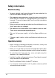
Safety information Electrical safety • To prevent electrical shock hazard, disconnect the power cable from the electrical outlet before relocating the system. • When adding or removing devices to or from the system, ensure that the power cables for the devices are unplugged before the signal cables are connected. Disconnect all power cables from the existing system before you add a device. • Before connecting or removing signal cables from the motherboard, ensure that all power cables are unplugged.
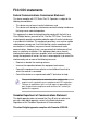
FCC/CDC statements Federal Communications Commission Statement This device complies with FCC Rules Part 15. Operation is subject to the following two conditions: • • This device may not cause harmful interference, and This device must accept any interference received including interference that may cause undesired operation. This equipment has been tested and found to comply with the limits for a Class B digital device, pursuant to Part 15 of the FCC Rules.
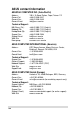
ASUS contact information ASUSTeK COMPUTER INC. (Asia-Pacific) Address: General Tel: General Fax: General Email: 150 Li-Te Road, Peitou, Taipei, Taiwan 112 +886-2-2894-3447 +886-2-2894-3449 info@asus.com.tw Technical Support: MB/Others (Tel): Notebook (Tel): Desktop/Server (Tel): Support Fax: Support Email: Web Site: Newsgroup: +886-2-2890-7121 (English) +886-2-2890-7122 (English) +886-2-2890-7123 (English) +886-2-2890-7698 tsd@asus.com.tw www.asus.com.tw cscnews.asus.com.
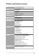
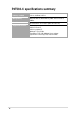
P4T533-C specifications summary CPU Socket 478 for Intel® Pentium® 4 On-die 512KB/256KB L2 cache Chipset Intel 82850E MCH Intel 82801 ICH2 Front Side Bus (FSB) 533/400 MHz Memory 4 x 184-pin PC1066/PC800-compliant Rambus DRAMs (RDRAMs) up to 2GB. memory. Expansion slots 1 x AGP 4X (1.
P4T533-C specifications summary x Industry Industrystandard standard PCI 2.2, USB 2.0, USB 1.1 Manageability Manageability WfM 2.0. DMI 2.0, WOL/WOR by PME, chassis intrusion, SMBus Form FormFactor Factor ATX form factor: 12 in x 9.6 in (30.5 cm x 24.
Chapter 1 Product introduction
Special Notice! Please refer to page 18 for special information about the requirements for the RIMM memory configuration.
Welcome! Thank you for buying the ASUS® P4T533-C motherboard! The ASUS P4T533-C motherboard delivers a host of new features to ensure long-lasting, superlative performance. The ASUS® P4T533-C motherboard is the prime choice for home PCs and workstations. The P4T533-C incorporates the Intel® Pentium® 4 Processor coupled with the Intel 850E chipset to set a new benchmark for an effective desktop platform solution.
1.2 Core Specifications The P4T533-C motherboard is designed and assembled according to the highest standards. This ASUS motherboard represents the latest advances and supplies users the finest components available today... Latest P4 Processor Technology: Intel® Pentium® 4 Socket 478 Northwood Processor. The Pentium 4 processor with 512KB L2 cache on a 0.13 micron processor core implements a 533MHz, quad-pumping system bus with a 133MHz system clock; the result: 4.2 GB/s data transfer rates are achieved.
1.3 Special Features Easy Overclocking • Quickly adjust CPU frequency multiples with BIOS in JumperFree™ Mode • Adjustable FSB/PCI frequency ratio (See pages 23, 24, 62 and 63.) • Adjustable Vcore Voltage (See pages 27 and 63.) ASUS EZ Plug™ This patented ASUS technology lets you use your existing power supply rather than buying a new ATX 12V power supply. The ASUS EZ Plug™ is a 4-pin auxillary +12V connector. This connector provides additional power required by the P4 CPU. (See page 35.
1.4 Motherboard Components Before installing the P4T533-C motherboard, take time to familiarize yourself with its configuration: understanding the motherboard makes upgrading easy. Sufficient knowledge of specifications prevents accidental damage. Location Processor Support Chipsets Main Memory Expansion Slots System I/O Hardware Monitoring Special Feature Network Feature Audio Features Power Form Factor 4 ® ™ Socket 478 for Intel P4 Processors ........................................
1.4.
Chapter 2 Hardware information
ASUS P4T533-C motherboard
2.1 Motherboard installation Before you install the motherboard, study the configuration of your chassis to ensure that the motherboard fits into it. The P4T533-C uses the ATX form factor that measures 24.5 cm (9.6 in.) x 30.5 cm (12.0 in.), a standard fit for most chassis. Make sure to unplug the power cord before installing or removing the motherboard. Failure to do so may cause you physical injury and damage motherboard components. 2.1.
2.2 Motherboard layout KBPWR 24.5cm (9.6in) ATX Power Connector USBPWR_12 RIMM_B2 (16/18 bit, 184-pin module) RIMM_B1 (16/18 bit, 184-pin module) Socket 478 PARALLEL PORT PWR_FAN COM2 Intel 82562ET Memory Controller Hub (MCH) Top:Line In Center:Line Out Below:Mic In PRI_IDE USB2.0 Top: T:USB4 RJ-45 B:USB3 30.5cm (12.0in) COM1 EZ_PLUG SEC_IDE T: USB1 B: USB2 RIMM_A2 (16/18 bit, 184-pin module) USB1.
2.2.1 Layout contents CPU, Memory and Expansion Slots 1) Socket 478 p. 12 Installing the CPU 2) Heatsink p. 13 Installing the Heatsink and Fan 3) Memory p. 16 System Memory Support 4) PCI 1/2/3/4/5 p. 19 32-bit PCI Bus Expansion Slots 5) AGP 4x p. 21 Accelerated Graphics Slot Motherboard Settings (Switches and Jumpers) 1) JEN p. 22 JumperFree Mode Setting (Disable/Enable) 2) DSW 6-10 p. 23 CPU Frequency Selection (Jumpers 6-10) 3) DSW 1-4 p. 24 CPU Frequency Multiple Setting 4) USB20_EN p. 25 USB 2.
21) FP_LO_SWL, FP_LO_SWR 22) FP_LINE_IN 23) FP_AUDIO 24) SPDIF_OUT 25) GAME 26) PLED 27) KEYLOCK 28) SPEAKER 29) MLED 30) SMI 31) PWRSW 32) RESET p. 39 p. 40 p. 40 p. 41 p. 41 p. 42 p. 42 p. 42 p. 42 p. 42 p. 42 p.
2.4 Central Processing Unit (CPU) 2.4.1 Overview The motherboard comes with a surface mount 478-pin Zero Insertion Force (ZIF) socket. This socket is specifically designed for the Intel® Pentium® 4 478 Processor. Gold Arrow ® P4T533-C P4T533-C Socket 478 The Intel Pentium 4 Processor in the 478-pin package uses the Flip-Chip Pin Grid Array 2 (FC-PGA2) package technology, and includes the Intel® NetBurst™ micro-architecture.
2.4.2 Installing the CPU Follow these steps to install a CPU: 1. Locate the Socket 478 and open it by pulling the lever gently sideways away from the socket. Then lift the lever upwards. The socket lever must be fully opened (90 to 100 degrees). Gold Arrow 90 - 100 2. Insert the CPU with the correct orientation. The gold arrow of the CPU must be oriented toward the inner corner of the socket base nearest to the hinge of the lever handle. The CPU fits in one orientation and should drop easily into place.
2.4.3 Installing the heatsink and fan The Intel® Pentium® 4 478 Processor requires a specially designed heatsink and fan assembly to ensure optimum thermal condition and performance. When you buy a boxed Intel Pentium 4 478 Processor, the package includes the heatsink, fan, and retention mechanism. In case you buy a CPU separately, make sure that you use only Intel certified heatsink and fan. Follow these steps to install the CPU heatsink and fan. 1.
2. Position the fan with the retention mechanism on top of the heatsink. Align and snap the four hooks of the retention mechanism to the holes on each corner of the module base. Make sure that the fan and retention mechanism assembly perfectly fits the heatsink and module base, otherwise you cannot snap the hooks into the holes. Retention Lock Retention Hook Snapped to the Retention Hole Keep the retention locks lifted upward while fitting the retention mechanism to the module base.
3. Push down the locks on the retention mechanism to secure the heatsink and fan to the module base. When secure, the retention locks should point to opposite directions. 2.4.4 Connecting the CPU fan cable When the fan, heatsink, and the retention mechanism are in place, connect the CPU fan cable to the connector on the motherboard labeled CPUFAN1. CPU Fan Connector (CPUFAN1) Don’t forget to connect the CPU fan connector! Hardware monitoring errors may occur if you fail to plug this connector.
2.5 System memory 2.5.1 Overview This motherboard has four 184-pin Rambus Inline Memory Modules (RIMM) sockets. These sockets support 64Mbit, 128Mbit, and 256Mbit Direct RDRAM technologies.
2.5.2 Installing Memory The memory module (RIMM) will fit in only one orientation. Do not touch the memory module’s connectors. Handle the module only by the edges. RIMM Sockets ® RIMM with Heat Spreader P4T533-C P4T533-C 184-Pin RIMM Sockets C-RIMM 1. Make sure that the notch keys in the module are aligned with the small ribs inside the RIMM sockets. MOUNTING NOTCH RDRAM (with heat spreader) NOTCH KEYS CONNECTORS (TOP VIEW) EJECTOR RIBS (inside socket) 2.
2.5.3 Removing Memory: To release a memory module, push both ejectors outward and pull the module straight up and out of the RIMM sockets. RIMM modules become extremely hot during operation. To reduce the risk of personal injury from hot surfaces, allow the modules to cool off before removing them. 2.5.4 General RIMM Memos: This motherboard supports 800MHz modules with the exception of NEC 800-45 series 800MHz RIMMS: the NEC 800-45 series modules do not function if the 533MHz CPU FSB is being used.
2.6 Expansion slots In the future, you may need to install expansion cards. The motherboard has five PCI slots and one Accelerated Graphics Port (AGP) slot. The following sub-sections describe the slots and the expansion cards that they support. Make sure to unplug the power cord before adding or removing expansion cards. Failure to do so may cause you physical injury and damage motherboard components. 2.6.1 Installing an expansion card Follow these steps to install an expansion card. 1.
2.6.2 Configuring an expansion card After physically installing the expansion card, configure the card by adjusting the software settings. 1. Turn on the system and change the necessary BIOS settings, if any. See Chapter 4 for information on BIOS setup. 2. Assign an IRQ to the card. Refer to the tables on the next page. 3. Install the software drivers for the expansion card.
2.6.3 PCI slots There are five 32-bit PCI slots in this motherboard. The slots support PCI cards such as a LAN card, SCSI card, USB card, and other cards that comply with PCI specifications. The following figure shows a LAN card installed on a PCI slot. 2.6.4 AGP slot This motherboard has an Accelerated Graphics Port (AGP) slot that supports AGP 4X 1.5V cards. CAUTION! This motherboard does not support 3.3V AGP cards; if a 3.
2.7 Jumpers The jumpers on the motherboard allow you to change some feature settings to suit your customized system configuration. Motherboard Frequency Settings (DSW Switches) The motherboard frequency is adjusted through the DSW switches. The illustration below shows the default position: DSW ON ON OFF 1 2 3 4 5 6 7 8 9 10 1. Frequency Multiple 2. Frequency Multiple 3. Frequency Multiple 4. Frequency Multiple 5. Reserved 6. Frequency Selection 7. Frequency Selection 8. Frequency Selection 9.
2. CPU External Frequency Selection (DSW Switches 6-10) This option tells the clock generator which frequency to send to the CPU, SDRAM and AGP clock, and sets the CPU’s External frequency. (The BUS Clock multiplied by the Frequency Multiple equals the CPU’s Internal frequency, or, the advertised CPU speed.) IMPORTANT: 1. To use this feature, JEN must be set to Jumper Mode, [1-2]. (See 1, JumperFree™ Mode.
3. CPU Frequency Multiple Setting (DSW Switches 1-4) Set DSW switches (1-4) to use the clock multiplier to coordinate the ratio of bus speeds with CPU settings. Set the DSW switches according to the internal speed of your processor and the bus frequency (133/100MHz). IMPORTANT: 1. To use this feature, JEN must be set to Jumper Mode, [1-2]. (See 1, JumperFree™ Mode.) DSW ON ON ON 1 2 3 4 5 6 7 8 9 10 1 2 3 4 5 6 7 8 9 10 16.0x 17.0x ON ON 18.0x ON 1 2 3 4 5 6 7 8 9 10 1 2 3 4 5 6 7 8 9 10 19.
4. USB 2.0 (3 pin USB20_EN) The USB 2.0 header (USB20_12) is enabled by the default setting, [1-2]. Select [2-3] to disable the header. USB20_EN ® 1 2 Enable (Default) P4T533-C 2 3 Disable P4T533-C USB2.0 Setting 5. USB Device Wake-Up (2x3 pin USBPWR_12, _34) The default setting, [1-2] (+5V) enables the USB wake-up feature. Reset these jumpers to pins [2-3] (+5VSB) to disable the wake up feature. The USB device wake-up feature requires a power supply that can provide at least 1A on the +5VSB lead.
6. Bass Center Setting (2x3 pin BCS1, BCS2) Use these jumpers in conjunction with the 6 channel Audio Driver and to adjust output for 4 or 6 speaker audio. No audio standard exists for the three pick-up surfaces on male audio jacks; therfore, it may be necessary to switch jumpers from the default position Center/Bass to Bass/Center in order to reroute signals among the internal leads of the Line-In, Line-Out, Mic female sockets.
8. CPU Over Voltage Setting (3 pin OVER_VOLT) This jumper controls the voltage to the CPU. The default [2-3] does not permit extra voltage to protect the CPU. Resetting the jumper to [1-2] permits extra voltage for the CPU through BIOS settings. It is not recommended to use extra voltage because it may prematurely shorten the life of the CPU and result in poor performance. OVER_VOLT 3 2 2 1 Enable Disable (Default) ® P4T533-C P4T533-C OVER_VOLT Setting 9.
10. Audio Setting (3 pin ADN#) The onboard 6 channel audio chip may be enabled or disabled using these jumpers. The defualt, [1-2], enables the audio setting. Disable the onboard audio system if using a PCI audio card on any of the expansion slots. ADN# 1 2 2 3 ® P4T533-C Enable (Default) Disable P4T533-C AUDIO Setting 11. Clear RTC RAM (CLRTC) This jumper clears the Real Time Clock (RTC) RAM in CMOS.
2.8 Connectors This section describes and illustrates the internal connectors on the motherboard. Some pins are used for connectors or power sources. These are clearly distinguished from jumpers in the Motherboard Layout. Placing jumper caps over these connector pins will cause damage to your motherboard. Ribbon cables should always be connected with the red stripe to Pin 1 in the connector scoket. 1.
3. Universal Serial Bus Ports: USB 1.1 and USB 2.0 (four x 4-pin USB) Four USB ports are available for connecting USB devices. Port 4 Port 1 USB 1.1 Port 2 Universal Serial Bus USB 2.0 Port 3 4. Parallel Port (Burgundy 25-pin PRINTER) You can enable the parallel port and choose the IRQ through Onboard Parallel Port (see 4.4.2 I/O Device Configuration). Serial printers must be connected to the serial port. Parallel Port (25-pin Female) 5.
6. Audio Connectors (Three 1/8” AUDIO) (optional) The Line Out (lime) connects a headphone or speakers. The Line In (light blue) connects a tape players or other audio sources. The Mic (pink) connects a microphone. In Out Mic 7. Fast-Ethernet Port Connector (RJ45) (optional) This RJ45 connector is located on top of the USB Ports 0 & 1. The RJ45 supports connectivity for local area networks.
8. IDE Activity LED (2-pin IDELED) This connector supplies power to the hard disk activity LED. The read or write activities of any device connected to the primary or secondary IDE connector cause this LED to light up. TIP: If the case-mounted LED does not light, try reversing the 2-pin plug. IDE_LED P4T533-C P4T533-C HD Activity LED Some pins are used for connectors or power sources. These are clearly distinguished from jumpers in the Motherboard Layout.
9. IDE Connectors (2 x 40-1 pin PRI_IDE / SEC_IDE) This connector supports the provided UltraDMA/100/66 IDE hard disk ribbon cable. Connect the cable’s blue connector to the IDE1 (recommended) or to the IDE2 connector; then connect the gray connector to the UltraDMA/100/66 slave device (hard disk drive) and the black connector to the UltraDMA/100/66 master device. It is recommended that you connect non-UltraDMA/100/66 devices to the secondary IDE connector.
10. Floppy disk drive connector (34-1 pin FLOPPY) This connector supports the provided floppy drive ribbon cable. After connecting one end to the motherboard, connect the other end to the floppy drive. (Pin 5 is removed to prevent incorrect insertion when using ribbon cables with pin 5 plug). FLOPPY PIN 1 ® NOTE: Orient the red markings on the floppy ribbon cable to PIN 1. P4T533-C P4T533-C Floppy Disk Drive Connector 11.
12. ATX power connectors (20-pin ATXPWR, 4-pin 12V EZ_PLUG, 4pin AUX12V) These connectors connect to an ATX 12V power supply. The plugs from the power supply are designed to fit these connectors in only one orientation. Find the proper orientation and push down firmly until the connectors completely fit. In addition to the 20-pin ATXPWR connector, this motherboard requires that you connect the 4-pin ATX +12V power plug to provide sufficient power to the CPU.
14. USB header (10-1 pin USB11_34) If the USB port connectors on the rear panel are inadequate, a USB header is available for additional USB port connectors. Connect the bundled 2-port USB connector set to this header and mount the USB bracket to an open slot in the chassis. GND USBP3+ USBP3– USB Power USB11_34 P4T533-C 6 5 1 NC GND USBP2+ USBP2– USB Power ® 10 P4T533-C USB 1.1 Header GND LDP2 LDM2 USB+5V 15.
16. Internal audio connectors (3 x 4-pin CD1, AUX, MODEM) (optional) These connectors allow you to receive stereo audio input from sound sources such as a CD-ROM, TV tuner, or MPEG card. The MODEM connector allows the onboard audio to interface with a voice modem card with a similar connector. It also allows the sharing of mono_in (such as a phone) and a mono_out (such as a speaker) between the audio and a voice modem card.
18. Infrared module connector (5-1 pin IR_CON) This connector supports an optional wireless transmitting and receiving infrared module. This module mounts to a small opening on system chassis that support this feature. You must also configure the UART2 Use As parameter in BIOS to set UART2 for use with IR. See section “4.4.2 I/O Device Configuration” for details.
IRRX GND IRTX SMBDATA +3VSB SMBCLK NC NC NC NC +5 V 20. ASUS iPanel / Infrared Connector (24-1 pin AFPANEL) This connector supports an optional ASUS iPanel, an easy to access drive bay with front I/O ports, status LEDs, and space reserved for a hard disk drive. Alternatively, if not using an ASUS iPanel, connect an optional wireless transmitting and receiving infrared module to the SIR connector for wireless transmitting/remote control functions through an external infrared module.
22. Front Panel Audio Line In Header (5 pin FP_LINE_IN) This connector suports audio input on left and right stereo audio channels. NOTE: The motherboard ships with Jumper caps over pins 1-2 and 4-5. Remove them only when making audio input connections. BLINE_IN_R LINE_IN_R AGND BLINE_LIN_L ALINE_LIN_L FP_LINE_IN ® P4T533-C P4T533-C LINE_IN Connector 23. Front Panel Audio Connector (10-1 pin FP_Audio) This is an interface connector for convenient front panel connections and audio control.
24. Digital audio connector (4-1 pin SPDIF_OUT) (Optional) This connector connects an S/PDIF audio module that allows digital instead of analog sound output. Connect one end of the audio cable to the S/PDIF Out connector on the motherboard, and the other end to the S/PDIF module. SPDIFOUT GND ® +5V SPDIF_OUT P4T533-C P4T533-C Digital Audio Connector 25. Game Header (16-1 pin GAME) This header supplies an external standard game connector to support joysticks and gamepads.
Panel Connector (20 pin PANEL) The following diagram illustrates items 26-32: P4S533 Message LED SMI Lead P4S533 System Panel Connectors Reset Ground +5V Ground Ground Speaker +5 V MLED ExtSMI# Ground PWR Ground +5 V PLED Power LED Speaker Connector Reset SW ATX Power Switch* * Requires an ATX power supply. 26. System Power LED Lead (3-1 pin PLED) This connector supplies the system power LED.
Chapter 3 Powering up
ASUS P4T533-C motherboard
3.1 Starting up for the first time 1. After making all the connections, replace the system case cover. 2. Be sure that all switches are off. 3. Connect the power cord to the power connector at the back of the system chassis. 4. Connect the power cord to a power outlet that is equipped with a surge protector. 5. Turn on the devices in the following order: a. Monitor b. External SCSI devices (starting with the last device on the chain) c.
3.2 Vocal POST Messages This motherboard includes the Winbond speech controller to support a special feature called the ASUS POST Reporter™. This feature gives you vocal POST messages and alerts to inform you of system events and boot status. In case of a boot failure, you will hear the specific cause of the problem. These POST messages are customizable using the Winbond Voice Editor software that came with your package. You can record your own messages to replace the default messages.
POST Message Action No keyboard detected • Check your keyboard if properly connected to the purple PS/2 connector on the rear panel. • See section “1.4 Motherboard Components” for the location of the connector. No floppy disk detected • Make sure you have connected a floppy disk to the floppy disk connector on the motherboard. • See section “2.8 Connectors.” No IDE hard disk detected • Make sure you have connected an IDE hard disk drive to the one of the IDE connectors on the motherboard.
3.3 Powering off the computer You must first exit the operating system and shut down the system before switching off the power. For ATX power supplies, you can press the ATX power switch after exiting or shutting down the operating system. If you use Windows 95/98/2000/XP, click the Start button, click Shut Down, then click the OK button to shut down the computer. The power supply should turn off after Windows shuts down.
Chapter 4 BIOS setup
ASUS P4T133-C motherboard
4.1 Managing and updating your BIOS It is recommended that you save a copy of the motherboard’s original BIOS to a bootable floppy disk in case you need to reinstall the original BIOS later. 4.1.1 Using ASUS EZ Flash to update the BIOS The ASUS EZ Flash feature allows you to easily update the BIOS without having to go through the long process of booting from a diskette and using a DOS-based utility.
5. At the prompt, “Please Enter File Name for NEW BIOS: _”, type in the BIOS file name that you downloaded from the ASUS website, then press . EZ Flash will automatically access drive A to look for the file name that you typed. When found, the following message appears on screen. [BIOS Information in File] BIOS Version: P4T533-C Boot Block WARNING! Continue to update the BIOS (Y/N)? _ If you accidentally typed in a wrong BIOS file name, the error message, “WARNING! File not found.” appears.
4.1.2 Using AFLASH from a Floppy Disk 1. Type FORMAT A:/S at the DOS prompt to create a bootable system disk. DO NOT copy AUTOEXEC.BAT and CONFIG.SYS to the disk. 2. Type COPY D:\AFLASH\AFLASH.EXE A:\ (assuming D is your CD-ROM drive) to copy AFLASH.EXE to the boot disk you created. NOTE! AFLASH works only in DOS mode. It does not function in the DOS prompt within Windows, and does not function with certain memory drivers that may be loaded when you boot from the hard drive.
4.1.3 Updating BIOS procedures Update the BIOS only if you have problems with the motherboard and you are sure that the new BIOS revision will solve your problems. Careless updating may result to more problems with the motherboard! 1. Download an updated ASUS BIOS file from the Internet (see the ASUS website: www.asus.com) and save to the boot floppy disk you created earlier. 2. Boot from the floppy disk. 3. At the “A:\” prompt, type AFLASH and then press . 4.
7. The utility starts to program the new BIOS information into the Flash ROM. The boot block is updated automatically only when necessary. This minimizes the possibility of boot problems in case of update failures. When the programming is done, the message “Flashed Successfully” appears. 8. Follow the onscreen instructions to continue. If you encounter problems while updating the new BIOS, DO NOT turn off the system because this may cause boot problems.
4.2 BIOS Setup program This motherboard supports a programmable Flash ROM that you can update using the provided utility described in section “4.1 Managing and updating your BIOS.” Use the BIOS Setup program when you are installing a motherboard, reconfiguring your system, or prompted to “Run Setup”. This section explains how to configure your system using this utility. Even if you are not prompted to use the Setup program, you may want to change the configuration of your computer in the future.
4.2.1 BIOS menu bar The top of the screen has a menu bar with the following selections: MAIN Use this menu to make changes to the basic system configuration. ADVANCED Use this menu to enable and make changes to the advanced features. POWER Use this menu to configure and enable Power Management features. BOOT Use this menu to configure the default system device used to locate and load the Operating System. EXIT Use this menu to exit the current menu or to exit the Setup program.
General help In addition to the Item Specific Help window, the BIOS setup program also provides a General Help screen. You may launch this screen from any menu by simply pressing or the + combination. The General Help screen lists the legend keys and their corresponding functions. Saving changes and exiting the Setup program See “4.7 Exit Menu” for detailed information on saving changes and exiting the setup program.
4.3 Main menu When you enter the Setup program, the following screen appears. System Time [XX:XX:XX] Sets the system to the time that you specify (usually the current time). The format is hour, minute, second. Valid values for hour, minute and second are Hour: (00 to 23), Minute: (00 to 59), Second: (00 to 59). Use the or + keys to move between the hour, minute, and second fields. System Date [XX/XX/XXXX] Sets the system to the date that you specify (usually the current date).
4.3.1 Primary & Secondary Master/Slave Type [Auto] Select [Auto] to automatically detect an IDE hard disk drive. If automatic detection is successful, Setup automatically fills in the correct values for the remaining fields on this sub-menu. If automatic detection fails, this may be because the hard disk drive is too old or too new. If the hard disk was already formatted on an older system, Setup may detect incorrect parameters.
[User Type HDD] Manually enter the number of cylinders, heads and sectors per track for the drive. Refer to the drive documentation or on the drive label for this information. After entering the IDE hard disk drive information into BIOS, use a disk utility, such as FDISK, to partition and format new IDE hard disk drives. This is necessary so that you can write or read data from the hard disk. Make sure to set the partition of the Primary IDE hard disk drives to active.
Translation Method [LBA] Select the hard disk drive type in this field. When Logical Block Addressing (LBA) is enabled, the 28-bit addressing of the hard drive is used without regard for cylinders, heads, or sectors. Note that LBA Mode is necessary for drives with more than 504MB storage capacity. Configuration options: [LBA] [LARGE] [Normal] [Match Partition Table] [Manual] Cylinders This field configures the number of cylinders. Refer to the drive documentation to determine the correct value.
SMART Monitoring [Disabled] This field allows you to enable or disable the S.M.A.R.T. (Self-Monitoring, Analysis and Reporting Technology) system that utilizes internal hard disk drive monitoring technology. This parameter is normally disabled because the resources used in the SMART monitoring feature may decrease system performance. Configuration options: [Disabled] [Enabled] PIO Mode [4] This option lets you set a PIO (Programmed Input/Output) mode for the IDE device.
4.3.2 Keyboard Features Boot Up NumLock Status [On] This field enables users to activate the Number Lock function upon system boot. Configuration options: [Off] [On] Keyboard Auto-Repeat Rate [6/Sec] This controls the speed at which the system registers repeated keystrokes. Options range from 6 to 30 characters per second.
Main menu items continued... Language [English] This field displays the BIOS language version. (This product does not support multi-language BIOS programs.) Supervisor Password [Disabled] / User Password [Disabled] These fields allow you to set passwords. To set a password, highlight the appropriate field and press . Type in a password then press . You can type up to eight alphanumeric characters. Symbols and other characters are ignored.
4.4 Advanced Menu CPU Speed [Manual] When the motherboard is set to JumperFree™ mode, this field allows you to select the internal frequency of the CPU. Select [Manual] if you want to make changes to the two subsequent fields. Selecting a frequency higher than the CPU manufacturer recommends may cause the system to hang or crash! CPU Frequency Multiple (when CPU Speed is set to [Manual]) This field is for unlocked processors only.
RDRAM/FSB Frequency Ratio [Auto] This field determines whether the memory clock frequency is set to be in synchronous or asynchronous mode with respect to the system frequency. The options that appear in the popup menu vary according to the CPU/PCI Frequency (MHz). Configuration options: [Auto] [1:1] [3:4] [3:5] [4:5] (The configuration options vary depending on the CPU frequency.) CPU VCore Setting [Auto] This field determines if the CPU Vcore is automatically scaled or set manually by the user.
4.4.1 Chip Configuration Graphics Aperture Size [64MB] This feature allows you to select the size of mapped memory for AGP graphic data. Configuration options: [4MB] [8MB] [16MB] [32MB] [64MB] [128MB] [256MB] Video Memory Cache Mode [UC] USWC (uncacheable, speculative write combining) is a new cache technology for the video memory of the processor. It can greatly improve the display speed by caching the display data.
4.4.2 I/O Device Configuration Floppy Disk Access Control [R/W] When set to [Read Only], this parameter protects files from being copied to floppy disks by allowing reads from, but not writes to, the floppy disk drive. The default setting [R/W] allows both reads and writes. Configuration options: [R/W] [Read Only] Onboard Serial Port 1 [3F8H/IRQ4] Onboard Serial Port 2 [Disabled] These fields allow you to set the addresses for the onboard serial connectors.
Parallel Port Mode [ECP+EPP] This field allows you to set the operation mode of the parallel port. [Normal] allows normal-speed operation but in one direction only; [EPP] allows bidirectional parallel port operation; [ECP] allows the parallel port to operate in bidirectional DMA mode; [ECP+EPP] allows normal speed operation in a two-way mode. Configuration options: [Normal] [EPP] [ECP] [ECP+EPP] ECP DMA Select [3] This field allows you to configure the parallel port DMA channel for the selected ECP mode.
4.4.3 PCI Configuration Slot 1, 2, 3, 4, 5 IRQ [Auto] These fields automatically assign the IRQ for each PCI slot. The default setting for each field is [Auto], which utilizes auto-routing to determine IRQ assignments. Configuration options: [Auto] [NA] [3] [4] [5] [7] [9] [10] [11] [12] [14] [15] PCI/VGA Palette Snoop [Disabled] Some non-standard VGA cards, like graphics accelerators or MPEG video cards, may not show colors properly. Setting this field to [Enabled] corrects this problem.
Onboard LAN [Enabled] This motherboard supports onboard LAN. Select the [Enabled] to activate this feature. Configuration options: [Disabled] [Enabled] Onboard LAN Boot Rom [Disabled] This motherboard supports boot up from onboard LAN Boot Rom. Select the [Enabled] to activate this feature. Configuration options: [Disabled] [Enabled] 4.4.3.
4.5 Power Menu The Power menu allows you to reduce power consumption. This feature turns off the video display and shuts down the hard disk after a period of inactivity. Power Management [User Defined] This field allows you to activate or deactivate the automatic power saving features. When set to [Disabled], the power management features do not function regardless of the other settings on this menu.
Video Off Option [Suspend -> Off ] This field determines when to activate the video off feature for monitor power management. Configuration options: [Always On] [Suspend -> Off] Video Off Method [DPMS OFF] This field defines the video off features. The Display Power Management System (DPMS) feature allows the BIOS to control the video display card if it supports the DPMS feature. [Blank Screen] only blanks the screen. Use this for monitors without power management or “green” features.
4.5.1 Power Up Control AC PWR Loss Restart [Disabled] This allows you to set whether or not to reboot the system after power interruptions. [Disabled] leaves your system off while [Enabled] reboots the system. [Previous State] sets the system back to the state it was before the power interruption. Configuration options: [Disabled] [Enabled] [Previous State] Wake/Power Up On Ext.
Power On By PS/2 Keyboard [Disabled] This parameter allows you to use specific keys on the keyboard to turn on the system. This feature requires an ATX power supply that provides at least 1A on the +5VSB lead. Configuration options: [Disabled] [Space Bar] [Ctrl-Esc] [Power Key] Power On By PS/2 Mouse [Disabled] This parameter allows you to use specific keys on the mouse to turn on the system. This feature requires an ATX power supply that provides at least 1A on the +5VSB lead.
4.5.2 Hardware Monitor MB Temperature [xxxC/xxxF] CPU Temperature [xxxC/xxxF] POWER Temperature [xxxC/xxxF] The onboard hardware monitor automatically detects the MB (motherboard) and CPU temperatures. CPU Fan Speed [xxxxRPM] or N/A Chassis Fan Speed [xxxxRPM] or N/A Power Fan Speed [xxxxRPM] or N/A The onboard hardware monitor automatically detects the CPU and chassis fan speeds and displays the fan speeds in revolutions per minute (RPM).
4.6 Boot Menu Boot Sequence The Boot menu allows you to select among the four possible types of boot devices listed using the up and down arrow keys. By using the <+> or key, you can promote devices and by using the <-> key, you can demote devices. Promotion or demotion of devices alters the priority which the system uses to search for a boot device on system power up. Configuration fields include Removable Devices, IDE Hard Drive, ATAPI CD-ROM, and Other Boot Device.
Plug & Play O/S [No] This field allows you to use a Plug-and-Play (PnP) operating system to configure the PCI bus slots instead of using the BIOS. When [Yes] is selected, interrupts may be reassigned by the OS. If you installed a nonPnP OS or if you want to prevent reassigning of interrupt settings, keep the default setting [No]. Configuration options: [No] [Yes] Reset Configuration Data [No] The Extended System Configuration Data (ESCD) contains information about non-PnP devices.
4.7 Exit Menu When you have made all of your selections from the various menus in the Setup program, save your changes and exit Setup. Select Exit from the menu bar to display the following menu. Pressing does not immediately exit this menu. Select one of the options from this menu or from the legend bar to exit. Exit Saving Changes Once you are finished making your selections, choose this option from the Exit menu to ensure the values you selected are saved to the CMOS RAM.
Load Setup Defaults This option allows you to load the default values for each of the parameters on the Setup menus. When you select this option or if you press , a confirmation window appears. Select [Yes] to load default values. Select Exit Saving Changes or make other changes before saving the values to the non-volatile RAM. Discard Changes This option allows you to discard the selections you made and restore the previously saved values. After selecting this option, a confirmation appears.
78 Chapter 4: BIOS Setup
Chapter 5 Software support
ASUS P4T533-C motherboard
5.1 Install an operating system This motherboard supports Windows 98/ME/NT/2000/XP operating systems (OS). Always install the latest OS version and corresponding updates so you can maximize the features of your hardware. 5.1.1 Windows 98 first time installation When you start Windows for the first time after installing the motherboard, Windows 98 detects all Plug-n-Play devices devices. Follow the Add New Hardware wizard to install the necessary device drivers. When prompted to restart, select No.
5.3 P4T533-C Motherboard Support CD NOTE: The support CD contents are subject to change without notice. To begin using your support CD disc, just insert it into your CD-ROM drive and the support CD installation menu should appear. If the menu does not appear, double-click or run D:\ASSETUP.EXE. 5.3.1 Installation Procedure Click on the name of the driver or program group to begin installation. Follow the instructions that appear on the setup screens. All drivers and programs install automatically.
Software: • Winbond Voice Editor: Installs a convenient utility to customize vocal POST messages. • ASUS PC Probe: Installs a smart utility to monitor your computer’s fan, temperature, and voltages. • ASUS Update: Instals a program that can help you update BIOS or download a BIOS image file. • Microsoft DirectX Driver: Installs basic drivers to enable compatibility with audio and other special functions. • PC-Cillin 2002: Installs the latest PC-cillin virus protection software.
5.4 ASUS PC Probe ASUS PC Probe is a convenient utility to continuously monitor your computer system’s vital components, such as fan rotations, Voltages, and temperatures. It also has a utility that lets you review useful information about your computer, such as hard disk space, memory usage, and CPU type, CPU speed, and internal/external frequencies through the DMI Explorer. 5.4.
5.4.2 Using ASUS PC Probe Monitoring Monitor Summary Shows a summary of the items being monitored. Temperature Monitor Shows the PC’s temperature. Temperature Warning threshold adjustment (Move the slider up to increase the threshold level or down to decrease the threshold level) Fan Monitor Shows the PC’s fan rotation. Fan Warning threshold adjustment (Move the slider up to increase the threshold level or down to decrease the threshold level) Voltage Monitor Shows the PC’s voltages.
Settings Lets you set threshold levels and polling intervals or refresh times of the PC’s temperature, fan rotation, and voltages. CPU Cooling System Setup Lets you select when to enable software CPU cooling. When When CPU Overheated is selected, the CPU cooling system is enabled whenever the CPU temperature reaches the threshold value. History Lets you record the current monitoring activity of a certain component of your PC for future reference.
Memory Shows the PC’s memory load, memory usage, and paging file usage. Device Summary Shows a summary of devices in your PC. DMI Explorer Shows information pertinent to the PC, such as CPU type, CPU speed, and internal/external frequencies, and memory size. Utility Lets you run programs outside of the ASUS Probe modules. To run a program, click Execute Program.
5.4.3 ASUS PC Probe Task Bar Icon Right-clicking the PC Probe icon will bring up a menu to open or exit ASUS PC Probe and pause or resume all system monitoring. When the ASUS PC Probe senses a problem with your PC, portions of the ASUS PC Probe icon changes to red, the PC speaker beeps, and the ASUS PC Probe monitor is displayed.
5.5 ASUS Live Update ASUS LiveUpdate is a utility that allows you to update your motherboard’s BIOS and drivers. The use of this utility requires that you are properly connected to the Internet through an Internet Service Provider (ISP). 1. Start ASUS Update. Launch the utility from your Windows Start menu:Programs/AsusUpdate. 2. Select an update method. 3. If you selected “downloading from the Internet,” you will need to select an Internet site.
5.6 3Deep Color Tuner The 3-Deep color tuner is designed to match your CRT or LCD color monitor to maximize the color quality of all graphical applications. Users may also tune their internet applications to match “true” internet source colors with the color displayed on the monitor. Simply run the setup program from the start menu and follow the instructions on the various setup/test screens. 5.6.1 3Deep Color Tuning 1. Select the type of monitor connected to the computer, either CRT or LCD. 2.
4. Select the color squares which most closely blend and match with the background. 5. The next step repeats the color matching process to achieve full color quality. 6. The tuning process is complete. Click on the bottom left button to connect to the internet and follow the instructions. 5.6.2 The 3Deep Control Panel Using the Windows Start button, activate the 3Deep Control Panel program from the 3Deep Applications group on the Main Program menu.
5.7 Winbond Voice Editor The Winbond Voice Editor software allows you to customize the vocal POST messages. Install the software from the software menu in the support CD. See section “5.2.3 Software menu”. To avoid conflicts, do not run the Winbond Voice Editor while running the ASUS PC Probe. Follow these steps to use the Winbond Voice Editor.
Changing the default language 1. Click on the Load button. a window showing the available languages appears. 2. Select your desired language then click Open. The event messages for the language you selected appear on the Voice Editor screen. For some languages, not all events have a corresponding message due to file size constraints. 3. Click on the Write button to update the EEPROM. 4. Click Yes on the confirmation window that appears.
Customizing your POST messages If your language is not in the selection or if you wish to record your own POST messages to replace the pre-installed wave files, you may easily do so. Follow these steps to customize your POST messages. 1. Launch the Voice Editor and take note of the list of POST events on the leftmost column of the screen. 2. Prepare your message for each event. The total compressed size for all the wave files must not exceed 1Mbit, so make your messages as short as possible. 3.
7. Click a POST event on the Voice Editor screen, then on the Edit button. The Event Sound Editor window appears. 8. Locate and select your wave file for the event then click on the arrow opposite Voice1. The file you selected appears on the space next to it. 9. Click OK to return to the Voice Editor screen. 10. Do steps 7 to 9 for the other events. 11. When done, click the Save button. A window appears prompting you to save your configuration. 12. Type a file name with a .flh extension, then click Save.
5.8 CyberLink PowerPlayer SE CyberLink PowerPlayer SE is an intelligent software player that can automatically detect and playback all kinds of video/audio files, CD and MP3 files as well. This is the only software you need for all types of video and audio files. No need to waste time identifying your file types. 5.8.1 Starting CyberLink PowerPlayer SE To start CyberLink Power Player, click the Windows Start button, point to Programs, and then CyberLink PowerPlayer SE, and then click PowerPlayer. 5.8.
5.9 CyberLink VideoLive Mail CyberLink’s VideoLive Mail Plus Ver 3.0 (a.k.a. VLM 3) is a convenient and excellent way to create professional quality video mails from PC video/audio input devices and to send the mails to any recipients via VLM 3’s built-in email system through the Internet. VLM 3’s mails comprise video, sound, or snapshot information; and thus may convey the most profound information to target audiences.
5.9.1 Starting VideoLive Mail To start VideoLive Mail, click the Windows Start button, point to Programs, and then CyberLink VideoLive Mail, and then click VideoLive Mail x.x. VLM 3’s Setup Wizard will start and guide you through configuring the video and audio input peripherals and to setup the e-mail environment. 1. Setup Wizard first will prompt a dialog to confirm that you want to configure the hardware and E-mail setting. Click Yes to continue the system parameter configuration. 2.
Glossary
ASUS P4T533-C motherboard
1394 1394 is the IEEE designation for a high performance serial bus tht offers data transfers at 100/200/400 Mbps. This serial bus defines both a back plane physical layer and a point-to-point cable-connected virtual bus. The primary application of the cable version is the integration of I/O connectivity at the back panel of personal computers using a low-cost, scalable, high-speed serial interface.
Bus Master IDE PIO (Programmable I/O) IDE requires that the CPU be involved in IDE access and waiting for mechanical events. Bus master IDE transfers data to/from the memory without interrupting the CPU. Bus master IDE driver and bus master IDE hard disk drives are required to support bus master IDE mode. Byte (Binary Term) One byte is a group of eight contiguous bits. A byte is used to represent a single alphanumeric character, punctuation mark, or other symbol. Cache Memory.
I/O (Input/Output) The data transfers from the input devices like a keyboard, mouse, or scanner, to the output devices like a printer or the monitor screen. I/O Address The specific memory location for a particular device. Two devices cannot share the same I/O address space. IrDA (Infrared Data Association) An internaltional organization that creates and promotes inter-operable, low cost, infrared data interconnection standards that support a walk-up, point-to-point model.
RDRAM (Rambus DRAM) Developed by Rambus, Inc., this type of memory can deliver up to 1.6GB of data per second. RDRAM is the first interface standard that can be directly implemented on high performance VLSI components such as, CMOS DRAMs, memory controllers, and graphics/video ICs. RAM (Random Access Memory). The computer’s primary storage area used to write, store, and retrieve information and program instructions which are passed to the CPU for processing.
Index
ASUS P4T533-C motherboard
Index Symbols 3Deep Color Tuner Using 88 A Accelerated Graphics Port 21 ASUS PC Probe Using 82 ASUS Update Using 87 ATAPI CD-ROM 74 Automatic Power Up 73 B BIOS Advanced Menu 62 Beep Codes 43 Boot Menu 74 Boot Sequence 74 Exit Menu 76 Language 61 Legend Bar 53 Main Menu 55 Menu Bar 53 Power Menu 69 Setup Defaults, loading 77 Setup Program 52 Smart BIOS 2 Sub-menu launching 54 Updating 47 BIOS Beep Codes 43 Boot Device Selection 74 Boot Up NumLock Status 60 Boot Virus Detection 75 C Central Processing Uni
S/PDIF 3 DIP Switches 22 E Expansion card installation 19 IRQ assigments 20 Expansion slots 19 F Floppy 3 Mode 55 Floppy Disk Drive Connector 9 H Hard Disk Drives (HDDs) CHS Capacity 58 Cylinders 58 Heads 58 LBA Capacity 58 Primary/Secondary Master 56 Primary/Secondary Slave 56 Sectors 58 Types 56 Hardware Monitor 73 Heatsink installation 13 K Keyboard Auto-Repeat Delay 60 Auto-Repeat Rate 60 Connector 29 Features 60 L Legacy Diskette 55 LiveUpdate 88 Using 88 M Motherboard IRQ Table 21 layout 8, 9 pl
Plug & Play O/S 75 POST Messages 44 POST messages customizing 92 Power Management 69 Power On Self Test 75 PowerPlayer SE Using 94 PS/2 Keyboard 29 PS/2 Keyboard Port 2 PS/2 Mouse 29 Function Control 63 PS/2 Mouse Port 2 S USB Legacy Support 64 Using 3Deep Color Tuner 88 ASUS Update 87 LiveUpdate 88 PC Probe 82 PowerPlayer SE 94 USWC 64 V VideoLive Mail 95 Using 95 Z ZIF socket 11 SDRAM Configuration 64 Serial Ports 65 Connectors 30 Slots AGP 21 PCI 21 Smart Card Reader 38 SMART Monitoring 59 Sony/Phil
104 Index