R P5A-VM Super7 microATX Motherboard USER’S MANUAL
USER'S NOTICE No part of this manual, including the products and software described in it, may be reproduced, transmitted, transcribed, stored in a retrieval system, or translated into any language in any form or by any means, except documentation kept by the purchaser for backup purposes, without the express written permission of ASUSTeK COMPUTER INC. (“ASUS”).
ASUS CONTACT INFORMATION ASUSTeK COMPUTER INC. (Asia-Pacific) Marketing Address: Telephone: Fax: Email: 150 Li-Te Road, Peitou, Taipei, Taiwan 112 +886-2-2894-3447 +886-2-2894-3449 info@asus.com.tw Technical Support Tel (English): Tel (Chinese): Fax: Email: Newsgroup: WWW: FTP: +886-2-2894-3447 ext. 706 +886-2-2894-3447 ext. 111 +886-2-2895-9254 tsd@asus.com.tw news2.asus.com.tw www.asus.com.tw ftp.asus.com.
CONTENTS I. INTRODUCTION ........................................................................... 7 How this Manual is Organized ........................................................ 7 Item Checklist .................................................................................. 7 II. FEATURES .................................................................................... 8 ASUS P5A-VM Motherboard .........................................................
CONTENTS Standard CMOS Setup ............................................................... Details of Standard CMOS Setup ......................................... BIOS Features Setup .................................................................. Details of BIOS Features Setup ............................................ Chipset Features Setup ............................................................... Details of Chipset Features Setup .........................................
FCC & DOC COMPLIANCE Federal Communications Commission Statement This device complies with FCC Rules Part 15. Operation is subject to the following two conditions: • • This device may not cause harmful interference, and This device must accept any interference received, including interference that may cause undesired operation. This equipment has been tested and found to comply with the limits for a Class B digital device, pursuant to Part 15 of the FCC Rules.
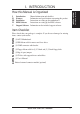
I. INTRODUCTION I. II. III. IV. V. Introduction Features Installation BIOS Software Support Software I. INTRODUCTION Sections/Checklist How this Manual is Organized Manual information and checklist Information and specifications concerning this product Instructions on setting up the motherboard Instructions on setting up the BIOS software Information on the included support software Item Checklist Please check that your package is complete.
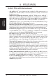
II. FEATURES ASUS P5A-VM Motherboard II. FEA TURES Features • ALi AGPset: ALi® (Acer Laboratories Inc.) Aladdin V AGPset with support for a 100MHz Front Side Bus (FSB), Accelerated Graphics Port (AGP), and all current Socket 7 processors. • Multi-Processor/Multi-Speed Support: AMD K6™-III/400 & faster, AMD K6™2/266 & faster, AMD K6™/166 & faster, AMD K5™/90–133, IBM®/Cyrix® 6x86MX™/ M II™ (PR166 & faster), IDT WinChip 2™ /240 & faster, IBM®/Cyrix® 6x86-PR166+ (Rev 2.
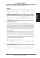
II. FEATURES Introduction to ASUS Smart Series Motherboards II. FEA TURES Smart Series Performance • SDRAM Optimized Performance: ASUS Smart Series motherboards support the new generation memory—Synchronous Dynamic Random Access Memory (SDRAM)—which increases the data transfer rate from 264MB/sec maximum using EDO memory to 528MB/sec max using SDRAM.
II. FEATURES II. FEA TURES Smart Series • Voltage Monitoring and Alert: System voltage levels are monitored to ensure stable current to critical motherboard components. Voltage specifications are more critical for future processors, so monitoring is necessary to ensure proper system configuration and management.
II. FEATURES Parts of the ASUS P5A-VM Motherboard (T): Top (B): Bottom ATI 3D Rage Pro AGP 2X or 3 DIMM ALi Aladdin V CPU ZIF Rage IIC AGP Sockets AGPset VGA (optional) Socket 7 ATI Multimedia Connector 8MB VGA Memory (Rage Pro) 4MB VGA Memory (Rage IIC) PS/2 Mouse (T) PS/2 Keyboard (B) II.
III. INSTALLATION ASUS P5A-VM Motherboard Layout VGAEN PS/2 KBPWR Top: Mouse Bottom: Keyboard BUS FREQ USB DIMM Socket 3 (64/72-bit, 168-pin module) CD_IN Tag RAM Rage Pro VGA: 8MB SDRAM IIC VGA: 4MB SDRAM 2 MB SDRAM INT_EN ALi Aladdin V M1541 AGPset ATI Multimedia Connector 512KB Pipelined Burst L2 Cache FLOPPY IDE2 IDE1 CPU ZIF Socket 7 ATX Power Connector PWR_TEMP CPU Thermal Sensor (Hardware Monitor) Line In Mic In GAME/AUDIO (optional) III.
III. INSTALLATION Jumpers 1) 2) 3) 4) 5) 6) 7) 8) 9) INT_EN VGAEN KBPWR VIO0/VIO1 OVER_FQ FS0, FS1, FS2, FS3 BF0, BF1, BF2 VID0, VID1, VID2, VID3 RTCCLR p. 14 p. 14 p. 15 p. 15 p. 15 p. 16 p. 16 p. 18 p.
III. INSTALLATION Installation Steps Before using your computer, you must complete the following steps: 1. Set Jumpers on the Motherboard 2. Install System Memory Modules 3. Install the Central Processing Unit (CPU) 4. Install Expansion Cards 5. Connect Ribbon Cables, Cabinet Wires, and Power Supply 6. Setup the BIOS Software 1. Jumpers III. INST ALLATION Jumpers WARNING! Computer motherboards, baseboards and components, such as SCSI cards, contain very delicate Integrated Circuit (IC) chips.
III. INSTALLATION 3. Keyboard Power (Wake) Up (KBPWR) This allows you to disable or enable the keyboard power or wake up function. Set to Enable if you want to use your keyboard (by pressing ) to power or wake up your computer. The default is set to Disable because not all computers have the appropriate ATX power supply. 01 1 1 2 2 3 3 Disable Enable R (DEFAULT) III.
III. INSTALLATION 6 CPU External (BUS) Frequency Selection (FS0, FS1, FS2, FS3) These jumpers tell the clock generator what frequency to send to the CPU, chipset, and AGP. These allow the selection of the CPU’s External frequency (or BUS Clock). The BUS Clock times the BUS Ratio equals the CPU's Internal frequency (the advertised CPU speed). 7.
III. INSTALLATION Set the jumpers by the Internal speed of your CPU as follows: Freq. Mult. BUS F. (Freq. Mult.) BF2 BF1 BF0 AMD-K6-III/450 AMD-K6-III/400 450MHz 400MHz A-4.5x 100MHz [2-3] [1-2] [1-2] [1-2] A-4.0x 100MHz [2-3] [1-2] [1-2] [1-2] [2-3] [2-3] [2-3] [2-3] [1-2] [2-3] AMD-K6-2/475 AMD-K6-2/450 AMD-K6-2/400 475MHz 450MHz 400MHz A-5.0x 95MHz [2-3] [1-2] [1-2] [2-3] A-4.5x 100MHz [2-3] [1-2] [1-2] [1-2] A-4.
III. INSTALLATION Compatible Cyrix CPU Identification The only Cyrix 6x86-PR166+ CPU that is supported on this motherboard must be Revision 2.7 or later. Look on the underside of the CPU for the serial number. The number should read G8DC6620A or later. 8. Voltage Regulator Output Selection (VID0, VID1, VID2, VID3) These jumpers set the VCORE voltage supplied to the CPU. Switching regulators allow some jumper settings to be the same for two voltages of different power planes.
III. INSTALLATION 9. Real Time Clock (RTC) RAM (RTCCLR) The CMOS RAM is powered by an onboard button cell battery. To clear the RTC data, (1) Turn off your computer, (2) Short solder points momentarily using a small metallic object, (3) Turn on your computer, (4) Hold down during bootup and enter BIOS setup to re-enter user preferences. 01 R RTCCLR Short solder points to Clear CMOS ASUS P5A-VM User’s Manual III.
III. INSTALLATION 2. System Memory (DIMM) This motherboard uses only Dual Inline Memory Modules (DIMMs). Sockets are available for 3.3Volt (power level) unbuffered Synchronous Dynamic Random Access Memory (SDRAM) of either 8, 16, 32, 64, 128MB, or 256MB to form a memory size between 8MB and 768MB. One side (with memory chips) of the DIMM takes up one row on the motherboard.
III. INSTALLATION DIMM Memory Installation Procedures: Insert the module(s) as shown. Because the number of pins are different on either side of the breaks, the module will only fit in the orientation as shown. DRAM SIMM modules have the same pin contacts on both sides. SDRAM DIMMs have different pin contacts on each side and therefore have a higher pin density. R 88 Pins III. INST ALLATION System Memory 20 Pins 60 Pins Lock P5A-VM 168-Pin DIMM Sockets The DIMMs must be 3.3Volt unbuffered SDRAMs.
III. INSTALLATION 3. Central Processing Unit (CPU) The motherboard provides a 321-pin ZIF Socket 7 that is backwards compatible with ZIF Socket 5 processors. The CPU that came with the motherboard should have a fan attached to it to prevent overheating. If this is not the case then purchase a fan before you turn on your system. WARNING! Without a fan circulating air on the CPU, the CPU can overheat and cause damage to both the CPU and the motherboard. III.
III. INSTALLATION 4. Expansion Cards WARNING! Make sure that you unplug your power supply when adding or removing expansion cards or other system components. Failure to do so may cause severe damage to both your motherboard and expansion cards. Expansion Card Installation Procedure: III. INST ALLATION Expansion Cards 1. Read your expansion card documentation on any hardware and software settings that may be required to setup your specific card. 2. Set any necessary jumpers on your expansion card. 3.
III. INSTALLATION To simplify this process, this motherboard complies with the Plug and Play (PNP) specification which was developed to allow automatic system configuration whenever a PNP-compliant card is added to the system. For PNP cards, IRQs are assigned automatically from those available. If the system has both Legacy and PNP ISA cards installed, IRQs are assigned to PNP cards from those not used by Legacy cards.
III. INSTALLATION 5. External Connectors WARNING! Some pins are used for connectors or power sources. These are clearly separated from jumpers in the Motherboard Layout. Placing jumper caps over these will cause damage to your motherboard. IMPORTANT: Ribbon cables should always be connected with the red stripe to Pin 1 on the connectors. Pin 1 is usually on the side closest to the power connector on hard drives and CD-ROM drives, but may be on the opposite side on floppy disk drives.
III. INSTALLATION 3. Parallel Port Connector (25-pin Female) You can enable the parallel port and choose the IRQ through “Onboard Parallel Port” in Chipset Features Setup of the BIOS SOFTWARE. NOTE: Serial printers must be connected to the serial port. Parallel (Printer) Port (25-pin Female) III. INST ALLATION Connectors 4. Serial Port COM1 (9-pin Male) and COM2 Connectors (10-1 pin Male) The two serial ports can be used for pointing devices or other serial devices.
III. INSTALLATION 5. Monitor (VGA) Output Connector (15-pin Female) This connector is for output to a VGA-compatible device. VGA Monitor (15-pin Female) 01 III. INST ALLATION Connectors 6. Floppy drive connector (FLOPPY, 34-1 pin block ) This connector supports the provided floppy drive ribbon cable. After connecting the single end to the board, connect the two plugs on the other end to the floppy drives.
III. INSTALLATION 8. Joystick/Midi Connector (15-pin Female) (with optional onboard audio) You may connect game joysticks or game pads to this connector for playing games. Connect Midi devices for playing or editing audio. Joystick/Midi (15-pin Female) 9. Universal Serial BUS Ports 1 & 2 (Two 4-pin Female Sockets) Two USB ports are available for connecting USB devices. III. INST ALLATION Connectors USB 1 Universal Serial Bus (USB) 2 10.
III. INSTALLATION TIP: You may configure two hard disks to be both Master drives using one ribbon cable on the primary IDE connector and another ribbon cable on the secondary IDE connector. You may install one operating system on an IDE drive and another on a SCSI drive and select the boot disk through the BIOS features Setup. 11. Chassis Intrusion Alarm Lead (4-1 pin CHASIS) This requires an external detection mechanism such as a chassis intrusion monitor/sensor or microswitch.
III. INSTALLATION 12. ATX Power Supply Connector (ATX, 20-pin block) This connector connects to a ATX power supply. The plug from the power supply will only insert in one orientation because of the different hole sizes. Find the proper orientation and push down firmly making sure that the pins are aligned. IMPORTANT: Make sure that your ATX power supply can supply at least 10mAmp on the 5-volt standby lead (+5VSB).
III. INSTALLATION 14 ATX Power Switch/Soft Power Switch Lead (PWR, 2 pins) The system power can be controlled by a momentary switch connected to this lead. Pushing the button once will switch the system between ON and SLEEP. Pushing the switch while in the ON mode for more than 4 seconds will turn the system off. The system power LED shows the status of the system’s power. 15. IDE Activity LED Lead (IDELED, 2 pins) This connector supplies power to the cabinet’s IDE activity LED.
III. INSTALLATION 21. Wake-on-LAN Activity Connector (3-pin WOLCON) The WOLCON connector allows the system to power up when there is a wakeup packet or signal is received from the network through the ASUS PCI-L101 LAN card (see section VI. ASUS LAN CARD). IMPORTANT: This feature requires that the WAKE On LAN Power Up Control is set to Enabled (see “Power Management Setup” under IV. BIOS SOFTWARE) and that your system has an ATX power supply with at least 720mA +5V standby power.
III. INSTALLATION 24 SMBus Connector (5-1 pin SMB) This connector allows you to connect SMBus devices. SMBus devices communicate by means of the SMBus with an SMBus host and/or other SMBus devices. The SMBus or System Management Bus is a specific implementation of an I2C bus, which is a multi-master bus, that is, multiple chips can be connected to the same bus and each one can act as a master by initiating data transfer. 01 SMBCLK Ground SMBDATA +5V III.
III. INSTALLATION 26. CPU Cooling Fan Connectors (FAN, 3 pins) These connectors support 3-pin cooling fans of 500mA (6W) or less with a minimum of 3,500RPM. Orientate the fans so that the heatsink fins allow airflow to go across the onboard heatsink(s) instead of the expansion slots. Depending on the fan manufacturer, the wiring and plug may be different. The red wire should be positive, while the black should be ground.
III. INSTALLATION Power Connection Procedures 1. After all jumpers and connections are made, close the system case cover. 2. Be sure that all switches are off (in some systems, marked with ). 3. Connect the power supply cord into the power supply located on the back of your system case according to your system user’s manual. 4. Connect the power cord into a power outlet that is equipped with a surge protector. III. INST ALLATION Power Connections 5.
IV. BIOS SOFTWARE Support Software AFLASH.EXE: This is the Flash Memory Writer utility that updates the BIOS by uploading a new BIOS file to the programmable flash ROM chip on the motherboard. To determine the BIOS version of your motherboard, check the last four numbers of the code displayed on the upper left-hand corner of your screen during bootup. Larger numbers represent a newer BIOS file. This file works only in DOS mode.
IV. BIOS SOFTWARE 2. Update BIOS Including Boot Block and ESCD This option updates the boot block, the baseboard BIOS, and the ACPI extended system configuration data (ESCD) parameter block from a new BIOS file. See the next page for procedures on downloading an updated BIOS file. To update your current BIOS, type [2] at the Main Menu and then press . The Update BIOS Including Boot Block and ESCD screen appears. Type the filename of your new BIOS and the path, for example, A:\XX2I1002.
IV. BIOS SOFTWARE Managing and Updating Your Motherboard’s BIOS Upon First Use of the Computer System 1. Create a bootable system floppy disk by typing [FORMAT A:/S] from the DOS prompt without creating “AUTOEXEC.BAT” and “CONFIG.SYS” files. 2. Copy AFLASH.EXE to the just created boot disk. 3. Run AFLASH.EXE from this new disk and select option 1. Save Current BIOS to File. See 1. Save Current BIOS To File on the previous page for more details and the rest of the steps.
IV. BIOS SOFTWARE 6. BIOS Setup The motherboard supports 5-volt programmable 2-Mbit Flash ROM chips. These memory chips can be updated when BIOS upgrades are released. Use the Flash Memory Writer utility to download the new BIOS file into the ROM chip as described in detail in this section. All computer motherboards provide a Setup utility program for specifying the system configuration and settings. If your motherboard came in a computer system, the proper configuration entries may have already been made.
IV. BIOS SOFTWARE Load Defaults Load BIOS Defaults loads the minimum settings for troubleshooting. Load Setup Defaults, on the other hand, is for loading optimized defaults for regular use. Choosing defaults at this level will modify all applicable settings. A section at the bottom of the preceding screen displays the control keys for this screen. Take note of these keys and their respective uses.
IV. BIOS SOFTWARE Time To set the time, highlight the “Time” field and then press either / or <+>/<–> to set the current time. Follow the hour, minute and second format. Valid values for hour, minute and second are: (Hour: (00 to 23), Minute: (00 to 59), Second: (00 to 59). If you do not want to modify the current time, press three times to go to HARD DISKS. NOTE: You can bypass the date and time prompts by creating an AUTOEXEC.BAT file.
IV. BIOS SOFTWARE Auto detection of hard disks on bootup For each field: Primary Master, Primary Slave, Secondary Master, and Secondary Slave, you can select Auto under the TYPE and MODE fields. This will enable auto detection of your IDE hard disk during bootup. This will allow you to change your hard disks (with the power off) and then power on without having to reconfigure your hard disk type.
IV. BIOS SOFTWARE BIOS Features Setup BIOS Features Setup consists of configuration entries that allow you to improve your system performance, or let you set up some system features according to your preference. Some entries are required by the motherboard’s design to remain in their default settings. IV. BIOS BIOS Features A section at the lower right of the screen displays the control keys you can use. Take note of these keys and their respective uses.
IV. BIOS SOFTWARE Quick Power On Self Test (Enabled) This field speeds up the Power-On Self Test (POST) routine by skipping retesting a second, third, and forth time. Setup default setting for this field is Enabled. A complete test of the system is done on each test. HDD Sequence SCSI/IDE First (IDE) When using both SCSI and IDE hard disk drives, IDE is always the boot disk using drive letter C (default setting of IDE). This new feature allows a SCSI hard disk drive to be the boot disk when set to SCSI.
IV. BIOS SOFTWARE IV. BIOS BIOS Features C8000 - CBFFF Shadow to DC000 - DFFFF Shadow (Disabled) These fields are used for shadowing other expansion card ROMs. If you install other expansion cards with ROMs on them, you will need to know which addresses the ROMs use to shadow them specifically. Shadowing a ROM reduces the memory available between 640KB and 1024KB by the amount used for this purpose. Boot Up NumLock Status (On) This field enables users to activate the Number Lock function upon system boot.
IV. BIOS SOFTWARE Details of Chipset Features Setup Chipset Features SDRAM Configuration (By SPD) This sets the optimal timing for items 2-4. Leave on default setting, depending on the memory modules that you are using. Default setting is By SPD, which configures items 2-4 by reading the contents in the SPD (Serial Presence Detect) device. This 8-pin serial EEPROM device stores critical parameter information about the module, such as memory type, size, speed, voltage interface, and module banks.
IV. BIOS SOFTWARE IV. BIOS Chipset Features Memory Hole At 15M-16M (Disabled) Enabling this feature reserves 15MB-16MB memory address space to ISA expansion cards that specifically require this setting. This makes the memory from 15MB and up unavailable to the system. Expansion cards can only access memory up to 16MB. The default is Disabled.
IV. BIOS SOFTWARE IV. BIOS Chipset Features Parallel Port Mode (ECP+EPP) This field allows you to set the operation mode of the parallel port. The setting Normal, allows normal-speed operation but in one direction only; EPP allows bidirectional parallel port operation at maximum speed; ECP allows the parallel port to operate in bidirectional mode and at a speed faster than the maximum data transfer rate; ECP+EPP allows normal speed operation in a two-way mode.
IV. BIOS SOFTWARE Power Management Setup Power Management Setup allows you to reduce power consumption. This feature turns off the video display and shuts down the hard disk after a period of inactivity. NOTE: SETUP Defaults are noted in parenthesis next to each function heading. Details of Power Management Setup IV. BIOS Power Management Power Management (User Define) This field acts as the master control for the power management modes.
IV. BIOS SOFTWARE IV. BIOS Power Management Video Off Method (DPMS OFF) This field defines the video off features. These options are available: DPMS OFF, DPMS Reduce ON, Blank Screen, V/H SYNC+Blank, DPMS Standby, and DPMS Suspend. The DPMS (Display Power Management System) features allow the BIOS to control the video display card if it supports the DPMS feature. Blank Screen only blanks the screen (for monitors without power management or “green” features).
IV. BIOS SOFTWARE Wake On LAN (Enabled) This allows you to remotely power up your system thorugh your network by sendng a wake-up frame or signal. With this feature, you can remotely upload/download data to/from systems during off-peak hours. Set to Enabled to use this feature. IMPORTANT: This feature requires the ASUS PCI-L101 LAN Card (see VI. ASUS LAN Card) and an ATX power supply with at least 720mA +5V standby power. ASUS P5A-VM User’s Manual IV.
IV. BIOS SOFTWARE PNP and PCI Setup This “PNP and PCI Setup” option configures the PCI bus slots. All PCI bus slots on the system use INTA#, thus all installed PCI cards must be set to this value. NOTE: SETUP Defaults are noted in parenthesis next to each function heading. Details of PNP and PCI Setup IV. BIOS Plug & Play/PCI PNP OS Installed (No) This field allows you to use a Plug-and-Play (PnP) operating system to configure the PCI bus slots instead of using the BIOS.
IV. BIOS SOFTWARE DMA x Used By ISA (No/ICU) These fields indicate whether or not the displayed DMA channel for each field is being used by a legacy (non-PnP) ISA card. Available options include: No/ICU and Yes. The first option, the default setting, indicates either that the displayed DMA channel is not used or an ICU is being used to determine if an ISA card is using that channel.
IV. BIOS SOFTWARE Load BIOS Defaults This “Load BIOS Defaults” option allows you to load the troubleshooting default values permanently stored in the BIOS ROM. These default settings are non-optimal and disable all high performance features. To load these default settings, highlight “Load BIOS Defaults” on the main screen and then press . The system displays a confirmation message on the screen. Press and then to confirm. Press and then to abort.
IV. BIOS SOFTWARE Supervisor Password and User Password IV. BIOS Passwords These two options set the system passwords. “Supervisor Password” sets a password that will be used to protect the system and the Setup utility; “User Password” sets a password that will be used exclusively on the system. By default, the system comes without any passwords. To specify a password, highlight the type you want and then press . A password prompt appears on the screen.
IV. BIOS SOFTWARE IDE HDD Auto Detection This “IDE HDD Auto Detection” option detects the parameters of an IDE hard disk drive, and automatically enters them into the Standard CMOS Setup screen. IV. BIOS Hard Disk Detect Up to four IDE drives can be detected, with parameters for each listed inside the box. To accept the optimal entries, press or else select from the numbers displayed under the OPTIONS field (2, 1, 3 in this case); to skip to the next drive, press .
IV. BIOS SOFTWARE IMPORTANT: If your hard disk was already formatted on an older previous system, incorrect parameters may be detected. You will need to enter the correct parameters manually or use low-level format if you do not need the data stored on the hard disk. If the parameters listed differ from the ones used when the disk was formatted, the disk will not be readable. If the auto-detected parameters do not match the ones that should be used for your disk, do not accept them.
V. SUPPORT SOFTWARE ASUS Smart Motherboard Support CD (Included only with motherboards with onboard hardware monitoring) NOTE: The support CD contents are subject to change at any time without notice. To begin using your support CD disc, just insert it into your CD-ROM drive and the support CD installation menu should appear. If the menu does not appear, double click or run D:\SETUP.EXE (assuming that your CD-ROM drive is drive D:). • V.
V. Support CD A. Video Driver .................................................................. 61 First Time Installation ...................................................................... Operating Systems ................................................................ Install Video Driver and Utility (Windows 95/98) .......................... Display Settings for Windows 95/98 ............................................... Adjustment Menu ...........................................................
V. Support CD E. Audio Software ............................................................. 83 V. Support CD Contents Audio Rack Installation ................................................................... Audio Rack Introduction ................................................................. The Command Center ...................................................................... Introduction ................................................................................
A. Video Driver A. V ideo Driver First Time Installation First Time Installation When you start Windows for the first time after the installation of your motherboard, Windows 95/98 will detect the onboard video chip (either ATI 3D Rage Pro AGP 2X or ATI 3D Rage IIC AGP, depending on your motherboard) and may attempt to install a driver from its system registry. When prompted to restart, select No. Then follow the normal installation procedure later in this section.
A. Video Driver A. V ideo Driver Windows 95/98 Install Video Driver and Utility (Windows 95/98) Install Video Driver and Utility installs the video driver necessary for your card to have higher performance, resolutions, and special features. You can also install the ATI Player–a software multimedia player which provides full-screen MPEG video playback with excellent color quality, plus a host of advanced multimedia features.
A. Video Driver A. Video Driver Display Settings Display Settings for Windows 95/98 To change resolution, color, and other display properties, either right-click the Windows 95/98 desktop and then choose Properties, double-click the Display icon in the Control Panel, or right-click the ATI icon in the system tray. Adjustment Menu You can adjust the screen output on the monitor from the Adjustment menu. Use the Position and Size arrows to center your screen and make it as large as possible.
A. Video Driver A. Video Driver Display Settings Color This allows you to adjust the Gamma level for your monitor and color levels for Red, Green, and Blue. You can save your settings by clicking Save As and typing in a file name. This allows you to recall previously saved settings. Click Defaults to restore all settings to their defaults. Settings This allows you to adjust the Color palette, Font size, and Display area.
B. Other Video Drivers Video Driver Installation for Windows NT 4.0 B. Other V ideo Drivers Windows NT 4.0 IMPORTANT! • Windows NT 3.5x does not support AGP cards. • Before installing the ASUS display driver in Windows NT 4.0, make sure that you have installed the Windows NT 4.0 Service Pack version 3.0 (available on the Internet at http://www.microsoft.com/isapi/support/bldqpage.idc?Product Page=q_servpk).
B. Other Video Drivers Video Driver Installation for IBM OS/2 The ATI OS/2 video driver is to be used for the English version of OS/2 only. To install ATI video drivers for OS/2 or OS/2 Warp, use the INSTALL program. This program checks the system for possible conflicts, sets the monitor type, and installs the enhanced display driver. B. Other V ideo Drivers IBM OS/2 To run the INSTALL program 1. Start OS/2. 2. Check that OS/2 is using a standard VGA driver and no other applications are running. 3.
B. Other Video Drivers ASUS P5A-VM User’s Manual B. Other V ideo Drivers IBM OS/2 To copy the driver files 1. Select Drivers Installation from the Main Menu. 2. Select IBM OS/2 from the list of applications. 3. Select Install for the correct version of OS/2. 4. Press to select the default destination directory or specify a destination directory for the OS/2 driver files. 5. After the files have been copied, press any key. 6. Press ESC to exit.
B. Other Video Drivers Select System Information (optional) The program will check the system for possible conflicts with the device, and display both the device and system configurations in the INFO BOX. In case of a conflict, it will issue a warning and suggest possible corrective actions. B.
B. Other Video Drivers VDIF Files (optional) VDIF files are VESA Display Information Format files. They contain all the necessary configuration parameters for getting optimal resolution and refresh rate operation from the specified monitor. Consult your monitor manufacturer for availability of VDIF files. B. Other V ideo Drivers VDIF Files If you have a VDIF file for your monitor, select it.
B. Other Video Drivers Advanced Setup (optional) If you wish to fine tune its settings for your monitor and system type, select Advanced Setup from the Main Menu. On-screen context sensitive help is displayed as you highlight each Advanced Menu item. B. Other V ideo Drivers Adv. / Diagnostics WARNING! The Advanced Configuration option allows you to use certain features that may add additional performance to your device. However these options may not be compatible with your system.
B. Other Video Drivers Troubleshooting System Lockup • • • • If you are using a memory manager such as QEMM or 386MAX you need to modify the command line in the CONFIG.SYS file so that the address of the graphics device video BIOS, C000 - C7FF, is excluded. For example, add “EXCLUDE = C000 - C7FF” to the command line. Remove all unnecessary boards. Disable shadow RAM. Ensure that the board is seated correctly and that the device has been installed using the proper utilities.
B. Other Video Drivers Memory aperture test failure or Diagnostics program locks or Reboots during aperture test If you receive an error message indicating that the memory aperture location is conflicting with your system memory, restart the INSTALL program as follows: INSTALL APMAP . Now when you enable Memory Aperture, you must select a location above but not overlapping System Memory (S), BIOS (B) or Reserved (R) locations. Not applicable for ISA cards. B.
B. Other Video Drivers Windows 95 mach64 enhanced display driver B. Other V ideo Drivers Driver / Player The Windows 95 mach64 enhanced display driver is capable of using monitor timing data contained within Windows 95. This data is selected by configuring a monitor type at Windows 95 installation time or via the “Settings” page of the display properties sheet.
B. Other Video Drivers Other Problems & Actions My monitor is not capable of high resolution or refresh rate. It depends on the display characteristics of your monitor. Consult your monitor documentation for the proper configuration. B. Other V ideo Drivers Descriptions/Actions After installing the driver, Windows 95 doesn't prompt me to restart and the driver still doesn't work after I restart my computer. You may have installed similar drivers before. Try the following steps to install: 1.
C. ATI Player ATI Player ATI Player and control panel (Win3.1x and Win95) If VIDEO drivers are installed, for playing video clips, the ATI Player icon will appear in the DeskTop. Double click on this icon to bring up the Video Screen as shown here: (Detailed button definitions are shown when holding the cursor over the individual buttons for a few seconds.) The Task Control Panel The Task control panel indicates what mode the player is in and what it’s doing.
C. ATI Player Playing Audio CDs (Only in window 95) PAL/NTSC Click the Audio CD button in the Task control panel to switch to Audio CD mode Random Loop Play Stop Pause Intro Play Position Slider Eject Setup Track Skip Skip Track Time Down Back Forward Up Mode Time Display Volume Control Volume Mute C. ATI Player Windows 95/3.x The Audio CD player has its own control panel for controlling the audio CD playback. You can use the Audio CD panel to play standard audio CDs.
C. ATI Player Playing Media Files Click the MPEG Playback button in the Task control panel to switch to playback mode. PAL/NTSC The Control panel changes to the Playback panel. To view/hide the Playback panel in Full Screen mode, press F2. Play/Stop First Frame Full Screen Advance Rewind File Name Last Frame Previous Audio Track Track Select Next Track Open File Volume Control Setup Dialog C. ATI Player Windows 95/3.
(This page was intentionally left blank) 78 ASUS P5A-VM User’s Manual
D. Audio Driver First Time Installation When starting Windows 95/98/NT 4.0, the operating system will automatically detect the ESS Solo-1 PCI Audio Driver. For Windows 95 1. When the New Hardware Found screen prompts for a driver, select Driver from disk provided by hardware manufacturer and insert the ASUS Support CD into your CD-ROM drive. 2. Click OK. 3. Click Browse. 4. Locate the D:\audio\w95 folder (where D is your CD-ROM Drive) and click OK. 5. Click OK again and the driver files will be copied. 6.
D. Audio Driver First Time Installation When starting Windows 95/98/NT 4.0, the operating system will detect that you have a new PCI Multimedia Device. Click Next when the Update Device Wizard screen appears. Click Other Locations to direct the wizard to the audio driver files. Click Browse to locate the \audio\W95 folder for Windows 95/98 or the \audio\Nt40 folder for Windows NT on the ASUS Support CD. D. Audio Driver First Installation Click OK to select the folder.
D. Audio Driver For Windows NT 4.0 D. Audio Driver Windows NT 4.0 1. Run the Windows NT “Multimedia” program located in Control Panel. (Start->Settings->Control Panels->Multimedia) 2. Click the Devices tab. 3. Select Audio Devices under Multimedia Devices. 4. Click Add. 5. Select Unlisted or Updated Driver under List of Drivers. 6. Click OK. 7. When Windows prompts you for the driver location, click Browse. 8. Locate the D:\audio\Nt40 folder (where D is your CD-ROM Drive).
(This page was intentionally left blank) 82 ASUS P5A-VM User’s Manual
E. Audio Software Audio Rack Installation Reinsert your CD or double click on your CD drive icon in My Computer to bring up the autorun screen or run Setup.exe in the root directory of the CD. Click Install Audio Utilities from the main menu. Audio Rack Introduction The AudioRack32 enables you to take advantage of your computer’s audio capabilities with all of the controls conveniently in one compact space. You can play audio CDs, wave files (in .WAV and .AUD formats), and MIDI files (in.MID and .
E. Audio Software The Command Center Counters Component Icons (DAT, MIDI, CD) Transport State Indicators Track or File Names Time Indexes Introduction The Command Center controls which parts of the AudioRack32 are displayed. You can display or hide any part of the AudioRack32 you choose, customizing its appearance to suit your needs or desires. It also displays information on the status of the different audio components. The Command Center Controls closes the AudioRack32 window.
E. Audio Software The Miniature Mode Introduction The Miniature mode is designed to give you full control of the AudioRack32 while using a minimum of space. You are able to effectively use the AudioRack32 and still have enough room on your desktop to run other applications. In the Miniature mode, you can play, pause, stop, and control the master volume of the AudioRack32. The Miniature Mode Controls stops currently playing tracks or files of active components.
E. Audio Software The Audio Mixer Introduction The Audio Mixer has two modes: Playback mode and Record mode. You can use these two modes to fully control which of your audio sources you are listening to or recording, how loud each of those sources are and how they are balanced. Each audio source has its own module with mute, balance and volume controls. In addition, the Audio Mixer provides special effects controls for chorus, reverb, treble, bass, and 3-D effects.
E. Audio Software The Digital Audio Player Introduction The Digital Audio Player enables you to play, record, and compress sound as .WAV files. In addition, you can play .AUD files. The .WAV files use PCM, which is the Windows‘ audio file format. The.AUD format uses ESPCM‘ compression to produce an audio file. Files are written directly to your hard disk as you record, enabling you to record very large files. Your only limitation is the amount of free space on your hard disk.
E. Audio Software The MIDI Player Introduction The MIDI Player enables you to play MIDI files with the .MID or .RMI file extensions. These MIDI (Musical Instrument Digital Interface) files can be produced by sequencer programs and then played back using the MIDI Player. You can also mix MIDI files with other audio sources. Or you can compile MIDI files in a playlist and play them back in any order you choose. The MIDI Player Controls plays the MIDI file currently loaded.
E. Audio Software The Compact Disk Player Introduction If you have a CD-ROM drive, you can play audio CDs. Check your hardware manual about setting up CD audio hardware and drivers. The Compact Disk Player uses intelligent CD playlist management: The Compact Disk Player maintains a record of each CD you play. It remembers the last playlist you used with each CD and loads that playlist automatically whenever you insert that CD. The Compact Disk Player Controls E.
E. Audio Software The Audio Recorder Introduction The Audio Recorder enables you to record, compress, store, and play back voice, music, and other sound. It provides settings for sound attributes such as mono/stereo, compression level, and sampling rate. You can use it to embed sound objects in documents created in applications that support object linking and embedding (OLE).
E. Audio Software Release Notes This information is provided for convenience only. Information here is subject to change without prior notice. View the installation CD for any updated information in Readme text files. The AudioRack also provides detailed online help (click the Help button on the “Command Center”) Disable Eject Button on the CD Player Under the Windows directory in the file “auddrive.ini”, there is a string “DisableEjectButton=0” under the [cdplayer] section.
F. Software Wavetable Install Software Wavetable (Windows 95/98) F. Wavetable Installation Insert the ASUS Support CD into your CDROM drive or double-click the CD drive icon in My Computer to bring up the autorun menu or run Setup.exe in the root directory of your CD-ROM driver. This will bring up the main menu. Click Install Software Wave Table. Select Install ESS Software Wavetable and click Next.
G. DMI Utility Desktop Management Interface (DMI) Introducing the ASUS DMI Configuration Utility G. DMI Utility DMI Introduction This motherboard supports DMI within the BIOS level and provides a DMI Configuration Utility to maintain the Management Information Format Database (MIFD). DMI is able to auto-detect and record information pertinent to a computer’s system such as the CPU type, CPU speed, and internal/external frequencies, and memory size.
G. DMI Utility Using the ASUS DMI Configuration Utility NOTE: The following screen displays are provided as examples only and may not reflect the screen contents on your system. Edit DMI (or delete) G. DMI Utility Using DMI Utility Use the ←→ (left-right) cursors to move the top menu items and the ↑↓ (up-down) cursor to move between the left hand menu items. The bottom of the screen will show the available keys for each screen. Press enter at the menu item to enter the right hand screen for editing.
G. DMI Utility G. DMI Utility Using DMI Utility Save MIFD You can save the MIFD (normally only saved to flash ROM) to a file by entering the drive and path here. If you want to cancel save, you may press ESC and a message “Bad File Name” appears here to show it was not saved. Load MIFD You can load the disk file to memory by entering a drive and path and file name here. Load BIOS Defaults You can load the BIOS defaults from a MIFD file and can clear all user modified and added data.
(This page was intentionally left blank) 96 ASUS P5A-VM User’s Manual