Deluxe Motherboard P5AD2-E
E1968 Revised edition V2 February 2005 Copyright © 2005 ASUSTeK COMPUTER INC. All Rights Reserved. No part of this manual, including the products and software described in it, may be reproduced, transmitted, transcribed, stored in a retrieval system, or translated into any language in any form or by any means, except documentation kept by the purchaser for backup purposes, without the express written permission of ASUSTeK COMPUTER INC. (“ASUS”).
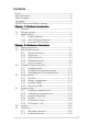
Contents Notices ................................................................................................ vi Safety information ............................................................................. vii About this guide ............................................................................... viii Typography ......................................................................................... ix P5AD2-E Deluxe specifications summary ............................................
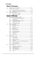
Contents Chapter 3: Powering up 3.1 3.2 3.3 Starting up for the first time ................................................ 3-1 Powering off the computer .................................................. 3-2 3.2.1 Using the OS shut down function ........................... 3-2 3.2.2 Using the dual function power switch .................... 3-2 ASUS POST Reporter™ .......................................................... 3-3 3.3.1 Vocal POST messages ............................................ 3-3 3.3.
Contents 4.5 4.6 4.7 4.4.6 Onboard Devices Configuration ............................ 4-29 4.4.7 PCI PnP ................................................................. 4-31 4.4.8 Speech Configuration ........................................... 4-32 Power menu ........................................................................ 4-33 4.5.1 Suspend Mode ...................................................... 4-33 4.5.2 Repost Video on S3 Resume ................................ 4-33 4.5.3 ACPI 2.
Notices Federal Communications Commission Statement This device complies with Part 15 of the FCC Rules. Operation is subject to the following two conditions: • This device may not cause harmful interference, and • This device must accept any interference received including interference that may cause undesired operation. This equipment has been tested and found to comply with the limits for a Class B digital device, pursuant to Part 15 of the FCC Rules.
Safety information Electrical safety • To prevent electrical shock hazard, disconnect the power cable from the electrical outlet before relocating the system. • When adding or removing devices to or from the system, ensure that the power cables for the devices are unplugged before the signal cables are connected. If possible, disconnect all power cables from the existing system before you add a device.
About this guide This user guide contains the information you need when installing and configuring the motherboard. How this guide is organized This user guide contains the following parts: • Chapter 1: Product introduction This chapter describes the features of the motherboard and the new technology it supports. • Chapter 2: Hardware information This chapter lists the hardware setup procedures that you have to perform when installing system components.
Conventions used in this guide To make sure that you perform certain tasks properly, take note of the following symbols used throughout this manual. D A N G E R / W A R N I N G : Information to prevent injury to yourself when trying to complete a task. C A U T I O N : Information to prevent damage to the components when trying to complete a task. I M P O R T A N T : Instructions that you MUST follow to complete a task. N O T E : Tips and additional information to help you complete a task.
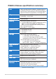
P5AD2-E Deluxe specifications summary CPU LGA775 socket for Intel® Pentium® 4/Celeron processor Compatible with Intel® PCG 04A and 04B processors Supports Intel® Enhanced Memory 64Technology (EM64T) Supports Enhanced Intel SpeedStep® Technology (EIST) Chipset Northbridge: Intel® 925XE Memory Controller Hub (MCH) Southbridge: Intel® ICH6R Front Side Bus 1066/800 MHz Memory Dual-channel memory architecture 4 x 240-pin DIMM sockets support unbufferred non-ECC DDR2-711 (FSB 1066)/DDR2-600 (FSB 800)/ DDR2
P5AD2-E Deluxe specifications summary Overclocking features (continuation) Stepless Frequency Selection (SFS) from 100 MHz up to 400 MHz at 1 MHz increment Adjustable FSB/DDR2 frequencies with fixed PCI/PCI-E frequencies Special features ASUS Post Reporter™ ASUS Q-Fan2 ASUS CrashFree BIOS 2 ASUS Multi-language BIOS ASUS MyLogo2 ASUS Stack Cool™ technology BIOS features 8 MB Flash ROM, AMI BIOS, PnP, DMI2.0, SM BIOS 2.3, WfM2.
P5AD2-E Deluxe specifications summary Support CD contents Device drivers ASUS PC Probe ASUS Update ASUS AI Booster Microsoft® DirectX 9.0c Anti-virus software Winbond Voice Editor Adobe Acrobat Reader ASUS Screensaver *Specifications are subject to change without notice.
This chapter describes the motherboard features and the new technologies it supports.
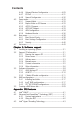
Chapter summary 1 1.1 Welcome! .............................................................................. 1-1 1.2 Package contents ................................................................. 1-1 1.3 Special features ....................................................................
1.1 Welcome! Thank you for buying an ASUS® P5AD2-E D e l u x e motherboard! The motherboard delivers a host of new features and latest technologies, making it another standout in the long line of ASUS quality motherboards! Before you start installing the motherboard, and hardware devices on it, check the items in your package with the list below. 1.2 Package contents Check your motherboard package for the following items.
1.3 Special features 1.3.1 Product highlights Latest processor technology The motherboard comes with a 775-pin surface mount Land Grid Array (LGA) socket designed for the Intel® Pentium® 4 processor in the 775-land package. The motherboard supports the Intel® Pentium® 4 processor with 1066/800/533 MHz Front Side Bus (FSB). The motherboard also supports the Intel® Hyper-Threading Technology and is fully compatible with Intel® 04B and 04A processors. See page 2-7 for details.
Serial ATA technology The motherboard supports the Serial ATA technology through the Serial ATA interfaces and the Intel® ICH6R. The SATA specification allows for thinner, more flexible cables with lower pin count, reduced voltage requirement, and up to 150 MB/s data transfer rate. See pages 2-26 and 2-27 for details. Dual RAID solution Onboard RAID controllers provide the motherboard with multi-RAID functionality that allows you to select the best RAID solution using IDE or Serial ATA hard disk drives.
Dolby® Digital Live Live™ The CMI9880 audio CODEC comes with an AC-3 encoder capable of transforming your computer’s digital audio contents into real-time Dolby® Digital stream. This digital stream passes through the S/PDIF out interfaces to an AC-3 decoder for 7.1-channel playback. See page 5-15 for details. S/PDIF digital sound ready The motherboard supports the S/PDIF technology through the S/PDIF interfaces on the rear panel.
1.3.2 ASUS AI Proactive features ASUS Stack Cool™ ASUS Stack Cool™ is an ideal thermal solution that reduces the heat dissipated by large capacitors and motherboard components. Stack Cool™ is a specially designed PCB installed under the motherboard CPU socket that effectively lowers the system temperature by as much as 10º Celsius. Cooler system temperature means more stable system performance, longer component life, and more silent operation. See page 2-3 for details.
CrashFree BIOS 2 This feature allows you to restore the original BIOS data from the support CD in case when the BIOS codes and data are corrupted. This protection eliminates the need to buy a replacement ROM chip. See page 4-5 for details. ASUS Q-Fan 2 technology The ASUS Q-Fan 2 technology smartly adjusts the fan speeds according to the system loading to ensure quiet, cool, and efficient operation. See pages 4-36 to 4-37 for details.
This chapter lists the hardware setup procedures that you have to perform when installing system components. It includes description of the jumpers and connectors on the motherboard.
Chapter summary 2 2.1 Before you proceed .............................................................. 2-1 2.2 Motherboard overview .......................................................... 2-2 2.3 Central Processing Unit (CPU) .............................................. 2-7 2.4 System memory ................................................................. 2-14 2.5 Expansion slots ................................................................... 2-18 2.6 Jumpers ........................
2.1 Before you proceed Take note of the following precautions before you install motherboard components or change any motherboard settings. • Unplug the power cord from the wall socket before touching any component. • Use a grounded wrist strap or touch a safely grounded object or to a metal object, such as the power supply case, before handling components to avoid damaging them due to static electricity. • Hold components by the edges to avoid touching the ICs on them.
2.2 Motherboard overview Before you install the motherboard, study the configuration of your chassis to ensure that the motherboard fits into it. Make sure to unplug the power cord before installing or removing the motherboard. Failure to do so can cause you physical injury and damage motherboard components. 2.2.1 Placement direction When installing the motherboard, make sure that you place it into the chassis in the correct orientation.
2.2.3 ASUS Stack Cool The motherboard comes with the ASUS Stack Cool, an innovative thermal solution that provides supplementary cooling to the motherboard. Stack Cool is a mini-PCB installed underneath the motherboard CPU socket to conduct heat away from motherboard components. Stack Cool effectively lowers the motherboard temperature by as much as 10ºC.
2.2.4 Motherboard layout MS1 24.5cm (9.6in) Super I/O ATX12V1 Side Speaker Out R Below: Intel 925XE Center/Subwoofer Top:Line In Center:Line Out Bottom:Mic In Marvell 88E8053 FLOPPY1 PRI_IDE1 USBPW12 USBPW34 EATXPWR Top:Rear Speaker Out Center: DDR2 DIMM_B2 (64 bit,240-pin module) USB2.0 Top: T: USB3 LAN port B: USB4 DDR2 DIMM_B1 (64 bit,240-pin module) Top: USB1 USB2 1394 DDR2 DIMM_A2 (64 bit,240-pin module) Bottom: DDR2 DIMM_A1 (64 bit,240-pin module) P5AD2-E CPU_FAN1 30.5cm (12.
2.2.5 Layout contents Slots Page 1. DDR2 DIMM slots 2-14 2. PCI slots 2-18 3. PCI Express slot 2-20 Jumpers Page 1. Clear RTC RAM (3-pin CLRTC1) 2-21 2. USB Device wake-up (3-pin USBPW12, USBPW34, USBPW56, USBPW78) 2-22 3. Keyboard power (3-pin KBPWR1) 2-22 Rear panel connectors Page 1. Parallel port 2-23 2. IEEE 1394a port 2-23 3. LAN (RJ-45) port 2-23 4. Rear Speaker Out port (gray) 2-23 5. Side Speaker Out port (black) 2-23 6. Line In port (light blue) 2-23 7.
Internal connectors Page 1. 2. Floppy disk drive connector (34-1 pin FLOPPY) Primary IDE connector (40-1 pin PRI_IDE1) 2-25 2-25 3. IDE RAID connectors (40-1 pin PRI_RAID1 [red], SEC_RAID1 [red]) 2-26 4. Serial ATA connectors (7-pin SATA1 [red], SATA2 [red], SATA3 [black], SATA4 [black) 2-26 5. Optical drive audio connector (4-pin CD) 2-28 6. Front panel audio connector (10-1 pin AAFP) 2-28 7. USB connectors (10-1 pin USB56, USB78) 2-29 8.
2.3 Central Processing Unit (CPU) The motherboard comes with a surface mount LGA775 socket designed for the Intel® Pentium® 4 processor in the 775-land package. 2.3.1 • Upon purchase of the motherboard, make sure that the PnP cap is on the socket and the socket contacts are not bent. Contact your retailer immediately if the PnP cap is missing, or if you see any damage to the PnP cap/socket contacts/motherboard components.
2. Press the load lever with your thumb (A), then move it to the left (B) until it is released from the retention tab. Retention tab A PnP cap Load lever B This side of the socket box should face you. To prevent damage to the socket pins, do not remove the PnP cap unless you are installing a CPU. 3. Lift the load lever in the direction of the arrow to a 135º angle. 4.
The CPU fits in only one correct orientation. DO NOT force the CPU into the socket to prevent bending the connectors on the socket and damaging the CPU! 6. Close the load plate (A), then push the load lever (B) until it snaps into the retention tab. A B The motherboard supports Intel® Pentium® 4 LGA775 processors with the Intel® Enhanced Memory 64 Technology (EM64T), Enhanced Intel SpeedStep® Technology (EIST), and Hyper-Threading Technology.
2.3.2 Installing the CPU heatsink and fan The Intel® Pentium® 4 LGA775 processor requires a specially designed heatsink and fan assembly to ensure optimum thermal condition and performance. • When you buy a boxed Intel® Pentium® 4 processor, the package includes the CPU fan and heatsink assembly. If you buy a CPU separately, make sure that you use only Intel®-certified multi-directional heatsink and fan.
A B B A B A A B Connect the CPU fan cable to the connector on the motherboard labeled CPU_FAN1. P5AD2-E DELUXE 3. Push down two fasteners at a time in a diagonal sequence to secure the heatsink and fan assembly in place. CPU_FAN1 GND CPU FAN PWR CPU FAN IN CPU FAN PWM 2. P5AD2-E DELUXE CPU fan connector Do not forget to connect the CPU fan connector! Hardware monitoring errors can occur if you fail to plug this connector.
2.3.3 Uninstalling the CPU heatsink and fan To uninstall the CPU heatsink and fan: 1. Disconnect the CPU fan cable from the connector on the motherboard. 2. Rotate each fastener counterclockwise. 3. Pull up two fasteners at a time in a diagonal sequence to disengage the heatsink and fan assembly from the motherboard. B A A B 4. 2-12 A B B A Carefully remove the heatsink and fan assembly from the motherboard.
5. Rotate each fastener clockwise to ensure correct orientation when reinstalling. Narrow end of the groove The narrow end of the groove should point outward after resetting. (The photo shows the groove shaded for emphasis.) Refer to the documentation in the boxed or stand-alone CPU fan package for detailed information on CPU fan installation.
2.4 System memory 2.4.1 Overview The motherboard comes with four Double Data Rate 2 (DDR2) Dual Inline Memory Modules (DIMM) sockets. A DDR2 module has the same physical dimensions as a DDR DIMM but has a 240-pin footprint compared to the 184-pin DDR DIMM. DDR2 DIMMs are notched differently to prevent installation on a DDR DIMM socket.
Qualified Vendors Lists DDR2-700/667 with 711 MHz (FSB 1066) capability* DDR2 Type Size Vendor Model B r a n d Side(s) C o m p o n e n t 700 256 MB ELPIDA EBE25UC8AAFV-DF-E 667 667 667 667 667 M378T6453FGN-CE6 SAMSUNG M378T6453FG0-CE6 SAMSUNG HYS64T32001HU-3-A Infineon BL3264AA664.
DDR2-533 DIMM support Size Vendor 256 MB ELPIDA 512 MB 1024 MB 256 MB 512 MB 512 MB 512 MB 512 MB 1024 MB 256 MB 512 MB 1024 MB 1024 MB 512 MB 512 MB 1024 MB 1024 MB 512 MB 512 MB 1024 MB 512 MB 256 MB 1024 MB 512 MB 512 MB 512 MB 1024 MB 1024 MB 256 MB 512 MB 512 MB 256 MB 512 MB 512 MB 512 MB 256 MB 512 MB 2-16 Model B r a n d Side(s) C o m p o n e n t EBE25UC8AAFV-DF-E SAMSUNG M378T6553BG0-CD5 SAMSUNG M378T2953BG0-CD5 SAMSUNG M378T3253FG0-CD5 SAMSUNG M378T6453FG0-CD5 Infineon HYS64T64000GU-3.
2.4.3 Installing a DIMM Unplug the power supply before adding or removing DIMMs or other system components. Failure to do so can cause severe damage to both the motherboard and the components. 2 To install a DIMM: 1. Unlock a DIMM socket by pressing the retaining clips outward. 2. Align a DIMM on the socket such that the notch on the DIMM matches the break on the socket. 3.
2.5 Expansion slots In the future, you may need to install expansion cards. The following sub-sections describe the slots and the expansion cards that they support. Make sure to unplug the power cord before adding or removing expansion cards. Failure to do so may cause you physical injury and damage motherboard components. 2.5.1 Installing an expansion card To install an expansion card: 1.
2.5.
2.5.4 PCI slots The PCI slots support cards such as a LAN card, SCSI card, USB card, and other cards that comply with PCI specifications. The figure shows a LAN card installed on a PCI slot. 2.5.5 PCI Express x16 slot This motherboard supports PCI Express x16 graphic cards that comply with the PCI Express specifications. The following figure shows a graphics card installed on the PCI Express x16 slot. 2.5.
2.6 1. Jumpers Clear RTC RAM (CLRTC) This jumper allows you to clear the Real Time Clock (RTC) RAM in CMOS. You can clear the CMOS memory of date, time, and system setup parameters by erasing the CMOS RTC RAM data. The onboard button cell battery powers the RAM data in CMOS, which include system setup information such as system passwords. To erase the RTC RAM: 1. Turn OFF the computer and unplug the power cord. 2. Remove the onboard battery. 3. Move the jumper cap from pins 1-2 (default) to pins 2-3.
2. USB device wake-up jumpers (3-pin USBPW12, USBPW34, USBPW56, USBPW78) Set these jumpers to +5V to wake up the computer from S1 sleep mode (CPU stopped, DRAM refreshed, system running in low power mode) using the connected USB devices. Set to +5VSB to wake up from S3 and S4 sleep modes (no power to CPU, DRAM in slow refresh, power supply in reduced power mode). The USBPWR12 and USBPWR34 jumpers are for the rear USB ports.
2.7 Connectors 2.7.1 Rear panel connectors 1 2 3 4 5 6 7 15 1. 14 13 12 11 10 9 8 P a r a l l e l p o r t . This 25-pin port connects a parallel printer, a scanner, or other devices. I E E E 1 3 9 4 a p o r t . This 6-pin IEEE 1394a port provides high-speed connectivity for audio/video devices, storage peripherals, PCs, or portable devices. L A N ( R J - 4 5 ) p o r t . This port allows Gigabit connection to a Local Area Network (LAN) through a network hub.
8. 9. M i c r o p h o n e p o r t ( p i n k ) . This port connects a microphone. C e n t e r / S u b w o o f e r p o r t ( y e l l o w o r a n g e ) . This port connects the center/subwoofer speakers. Refer to the audio configuration table below for the function of the audio ports in 2, 4, 6, or 8-channel configuration.
2.7.2 1. Internal connectors Floppy disk drive connector (34-1 pin FLOPPY) This connector is for the provided floppy disk drive (FDD) signal cable. Insert one end of the cable to this connector, then connect the other end to the signal connector at the back of the floppy disk drive. P5AD2-E DELUXE Pin 5 on the connector is removed to prevent incorrect cable connection when using a FDD cable with a covered Pin 5. PIN 1 FLOPPY NOTE: Orient the red markings on the floppy ribbon cable to PIN 1.
3. IDE RAID connectors (40-1 pin PRI_RAID1 [red], SEC_RAID1 [red]) These connectors are for Ultra ATA 133/100/66 signal cables. The IDE RAID connectors support up to four IDE hard disk drives that you can configure as a disk array through the onboard IDE RAID controller. Refer to Chapter 5 for details on how to set up RAID configurations. P5AD2-E DELUXE These connectors are set to I D E M o d e by default.
P5AD2-E DELUXE These connectors are set to S t a n d a r d I D E mode by default. In S t a n d a r d I D E mode, you can connect Serial ATA boot/data hard disk drives to these connectors. If you intend to create a Serial ATA RAID set using these connectors, set the C o n f i g u r e S A T A A s item in the BIOS to [RAID]. See section “4.3.6 IDE Configuration” on page 4-16 for details.
5. Optical drive audio connector (4-pin CD) ® Right Audio Channel Ground Ground Left Audio Channel P5AD2-E DELUXE This connector is for the 4-pin audio cable that connects to the audio connector at the back of the optical drive. CD P5AD2-E DELUXE CD audio connector Enable the CD-IN function in the audio utility when using this connector. 6.
7. USB connectors (10-1 pin USB56, USB78) P5AD2-E DELUXE These connectors are for USB 2.0 ports. Connect the USB/GAME module cable to any of these connectors, then install the module to a slot opening at the back of the system chassis. These USB connectors comply with USB 2.0 specification that supports up to 480 Mbps connection speed. P5AD2-E DELUXE USB 2.
9. GAME/MIDI port connector (16-1 pin GAME1) P5AD2-E DELUXE This connector is for a GAME/MIDI port. Connect the USB/GAME module cable to this connector, then install the module to a slot opening at the back of the system chassis. The GAME/MIDI port connects a joystick or game pad for playing games, and MIDI devices for playing or editing audio files. +5V J1B2 J1CY GND GND J1CX J1B1 +5V ® MIDI_IN J2B2 J2CY MIDI_OUT J2CX J2B1 +5V GAME1 P5AD2-E DELUXE GAME connector 1 0 .
1 1 . CPU, Chassis, and Power Fan connectors (3-pin CPU_FAN1, PWR_FAN1, CHA_FAN1, CHA_FAN2) The fan connectors support cooling fans of 350 mA ~ 2000 mA (24 W max.) or a total of 1 A ~ 3.48 A (41.76 W max.) at +12V. Connect the fan cables to the fan connectors on the motherboard, making sure that the black wire of each cable matches the ground pin of the connector.
1 3 . ATX power connectors (24-pin EATXPWR1, 4-pin ATX12V1) These connectors are for ATX power supply plugs. The power supply plugs are designed to fit these connectors in only one orientation. Find the proper orientation and push down firmly until the connectors completely fit. • Use of an ATX 12 V Specification 2.0 -compliant power supply unit (PSU) that provides a minimum power of 350 W is recommended for a fully-configured system.
1 4 . System panel connector (20-pin PANEL1) +5V Ground Ground Speaker PLED- SPEAKER IDE_LED Reset Ground PWR Ground PANEL1 IDE_LED+ IDE_LED- ® PLED PLED+ P5AD2-E DELUXE This connector supports several chassis-mounted functions. RESET PWRSW P5AD2-E DELUXE System panel connector The sytem panel connector is color-coded for easy connection. Refer to the connector description below for details. • • • • • System power LED (Green 3-pin PLED) This 3-pin connector is for the system power LED.
2-34 Chapter 2: Hardware information
This chapter describes the power up sequence, the vocal POST messages, and ways of shutting down the system.
Chapter summary 3 3.1 Starting up for the first time ................................................ 3-1 3.2 Powering off the computer .................................................. 3-2 3.3 ASUS POST Reporter™ ..........................................................
3.1 Starting up for the first time 1. After making all the connections, replace the system case cover. 2. Be sure that all switches are off. 3. Connect the power cord to the power connector at the back of the system chassis. 4. Connect the power cord to a power outlet that is equipped with a surge protector. 5. Turn on the devices in the following order: a. Monitor b. External SCSI devices (starting with the last device on the chain) c. System power 6.
3.2 Powering off the computer 3.2.1 Using the OS shut down function If you are using Windows® 2000: 2. Click the S t a r t button then click S h u t D o w n . . . Make sure that the S h u t D o w n option button is selected, then click the O K button to shut down the computer. 3. The power supply should turn off after Windows® shuts down. 1. If you are using Windows® XP: 2. Click the S t a r t button then select T u r n O f f C o m p u t e r .
3.3 ASUS POST Reporter™ This motherboard includes the Winbond speech controller to support a special feature called the ASUS POST Reporter™. This feature lets you hear vocal messages during POST that alerts you of system events and boot status. In case of a boot failure, you will hear the specific cause of the problem. These POST messages are customizable using the Winbond Voice Editor software that came with your package. You can record your own messages to replace the default messages. 3.3.
POST Message Action CPU temperature too high • Check if the CPU fan is working properly. CPU fan failed • Check the CPU fan and make sure it turns on after you apply power to the system. • Make sure that your CPU fan supports the fan speed detection function. • Check your power supply and make sure it is not defective. • Call ASUS technical support for assistance. See the “ASUS contact information” on the inside front cover of this user guide.
3.3.2 Winbond Voice Editor The Winbond Voice Editor software allows you to customize the vocal POST messages. You can install this application from the support CD. To avoid conflicts, do not run the Winbond Voice Editor while running the ASUS PC Probe application. Launching the Voice Editor You can launch the program from the Windows® desktop by clicking S t a r t > A l l P r o g r a m s > W i n b o n d V o i c e E d i t o r > V o i c e E d i t o rr. The Winbond Voice Editor screen appears.
Changing the default language To change the default language: 1. Click the L o a d button from the Voice Editor main window. A window with the available languages appears. 2. Select your desired language, then click O p e n n. The event messages for the language you selected appear on the Voice Editor main window. Not all events on some languages have a corresponding message due to file size constraints. 3. 4. Click the W r i t e button from the Voice Editor main window to update the EEPROM.
Customizing your POST messages The Voice Editor application allows you to record your own POST messages if your language is not supported or if you wish to to replace the pre-installed wave files. To customize your POST messages. 1. Launch the Voice Editor application and note the list of POST events on the leftmost column of the screen. 2. Prepare your message for each event. 3. Use a recording software (e.g. Windows® Recorder) to record your messages, then save the messages as wave files (.WAV).
6. Select a POST event on the Voice Editor main window, then click the E d i t button. The E v e n t S o u n d E d i t o r window appears. 7. Locate and select your wave file for the event, then click on the arrow opposite Voice1. The file you select appears on the space next to it. Click O K to return to the Voice Editor main window. 8. 9. Do steps 6 to 8 for the other events. 10. When done, click S a v e e. A window appears prompting you to save your configuration. 11. Type a file name with an .
This chapter tells how to change the system settings through the BIOS Setup menus. Detailed descriptions of the BIOS parameters are also provided.
Chapter summary 4 4.1 Managing and updating your BIOS ........................................ 4-1 4.2 BIOS setup program ........................................................... 4-11 4.3 Main menu .......................................................................... 4-14 4.4 Advanced menu .................................................................. 4-19 4.5 Power menu ........................................................................ 4-33 4.6 Boot menu .....................
4.1 Managing and updating your BIOS The following utilities allow you to manage and update the motherboard Basic Input/Output System (BIOS) setup. 1. 2. 3. 4. A S U S A F U D O S (Updates the BIOS in DOS mode using a bootable floppy disk.) A S U S C r a s h F r e e B I O S 2 (Updates the BIOS using a bootable floppy disk or the motherboard support CD when the BIOS file fails or gets corrupted.) A S U S E Z F l a s h (Updates the BIOS in DOS mode using a floppy disk or the motherboard support CD.
Windows® 2000 environment To create a set of boot disks for Windows® 2000: a. Insert a formatted, high density 1.44 MB floppy disk into the drive. b. Insert the Windows® 2000 CD to the optical drive. c. Click S t a r tt, then select R u n n. d. In the O p e n field, type D:\bootdisk\makeboot a: assuming that D is your optical drive letter. e. Press , then follow screen instructions to continue. 2. Copy the original or the latest motherboard BIOS file to the bootable floppy disk. 4.1.
3. Press . The utility copies the current BIOS file to the floppy disk. A:\>afudos /oOLDBIOS1.rom AMI Firmware Update Utility - Version 1.19(ASUS V2.07(03.11.24BB)) Copyright (C) 2002 American Megatrends, Inc. All rights reserved. Reading flash ..... done Write to file...... ok A:\> The utility returns to the DOS prompt after copying the current BIOS file. Updating the BIOS file To update the BIOS file using the AFUDOS utility: 1. Visit the ASUS website (www.asus.
4. The utility verifies the file and starts updating the BIOS. A:\>afudos /iP5AD2ED.rom AMI Firmware Update Utility - Version 1.19(ASUS V2.07(03.11.24BB)) Copyright (C) 2002 American Megatrends, Inc. All rights reserved. WARNING!! Do not turn off power during flash BIOS Reading file ....... done Reading flash ...... done Advance Check ...... Erasing flash ...... done Writing flash ...... 0x0008CC00 (9%) Do not shut down or reset the system while updating the BIOS to prevent system boot failure! 5.
4.1.3 ASUS CrashFree BIOS 2 utility The ASUS CrashFree BIOS 2 is an auto recovery tool that allows you to restore the BIOS file when it fails or gets corrupted during the updating process. You can update a corrupted BIOS file using the motherboard support CD or the floppy disk that contains the updated BIOS file. • Prepare the motherboard support CD or the floppy disk containing the updated motherboard BIOS before using this utility.
Recovering the BIOS from the support CD To recover the BIOS from the support CD: 1. Remove any floppy disk from the floppy disk drive, then turn on the system. 2. Insert the support CD to the optical drive. 3. The utility displays the following message and automatically checks the floppy disk for the original or updated BIOS file. Bad BIOS checksum. Starting BIOS recovery... Checking for floppy...
4.1.4 ASUS EZ Flash utility The ASUS EZ Flash feature allows you to update the BIOS without having to go through the long process of booting from a floppy disk and using a DOS-based utility. The EZ Flash utility is built-in the BIOS chip so it is accessible by pressing + during the Power-On Self Tests (POST). To update the BIOS using EZ Flash: 1. Visit the ASUS website (www.asus.com) to download the latest BIOS file for the motherboard and rename the same to P 5 A D 2 E D . R O M M. 2.
4.1.5 ASUS Update utility The ASUS Update is a utility that allows you to manage, save, and update the motherboard BIOS in Windows® environment. The ASUS Update utility allows you to: • Save the current BIOS file • Download the latest BIOS file from the Internet • Update the BIOS from an updated BIOS file • Update the BIOS directly from the Internet, and • View the BIOS version information. This utility is available in the support CD that comes with the motherboard package.
Updating the BIOS through the Internet To update the BIOS through the Internet: 1. Launch the ASUS Update utility from the Windows® desktop by clicking Start > Programs > ASUS > ASUSUpdate > ASUSUpdate e. The ASUS Update main window appears. 2. Select U p d a t e B I O S f r o m t h e I n t e r n e t option from the drop-down menu, then click N e x tt. ASUS P5AD2-E Deluxe 3. Select the ASUS FTP site nearest you to avoid network traffic, or click A u t o S e l e c tt. Click N e x tt.
4. From the FTP site, select the BIOS version that you wish to download. Click Next. 5. Follow the screen instructions to complete the update process. The ASUS Update utility is capable of updating itself through the Internet. Always update the utility to avail all its features. Updating the BIOS through a BIOS file To update the BIOS through a BIOS file: 1. 2. 3. 4.
4.2 BIOS setup program This motherboard supports a programmable firmware chip that you can update using the provided utility described in section “4.1 Managing and updating your BIOS.” Use the BIOS Setup program when you are installing a motherboard, reconfiguring your system, or prompted to “Run Setup”. This section explains how to configure your system using this utility. Even if you are not prompted to use the Setup program, you can change the configuration of your computer in the future.
4.2.1 BIOS menu screen Menu items Menu bar Configuration fields System Time System Date Legacy Diskette A Language Primary IDE Master Primary IDE Slave Third IDE Master Third IDE Slave Fourth IDE Master Fourth IDE Slave IDE Configuration [11:51:19] [Thu 05/07/2004] [1.44M, 3.5 in] [English] : : : : : : [ST320413A] [ASUS CD-S520/A] [Not Detected] [Not Detected] [Not Detected] [Not Detected] System Information Sub-menu items 4.2.2 General help Use [ENTER], [TAB] or [SHIFT-TAB] to select a field.
4.2.4 Menu items The highlighted item on the menu bar displays the specific items for that menu. For example, selecting M a i n shows the Main menu items. System Time System Date Legacy Diskette A Language Primary IDE Master Primary IDE Slave Secondary IDE Master Secondary IDE Slave Third IDE Master Fourth IDE Master IDE Configuration [11:10:19] [Thu 03/27/2003] [1.44M, 3.5 in] [English] :[ST320413A] :[ASUS CD-S340] :[Not Detected] :[Not Detected] :[Not Detected] :[Not Detected] 4.2.
4.3 Main menu When you enter the BIOS Setup program, the M a i n menu screen appears, giving you an overview of the basic system information. Refer to section “4.2.1 BIOS menu screen” for information on the menu screen items and how to navigate through them. System Time System Date Legacy Diskette A Language Primary IDE Master Primary IDE Slave Third IDE Master Third IDE Slave Fourth IDE Master Fourth IDE Slave IDE Configuration [11:51:19] [Thu 05/07/2004] [1.44M, 3.
4.3.5 Primary, Third and Fourth IDE Master/Slave The BIOS automatically detects the connected IDE devices. There is a separate sub-menu for each IDE device. Select a device item, then press to display the IDE device information. Primary IDE Master Device : Hard Disk Vendor : ST320413A Size : 20.
PIO Mode [Auto] Selects the PIO mode. Configuration options: [Auto] [0] [1] [2] [3] [4] SMART Monitoring [Auto] Sets the Smart Monitoring, Analysis, and Reporting Technology. Configuration options: [Auto] [Disabled] [Enabled] 32Bit Data Transfer [Disabled] Enables or disables 32-bit data transfer. Configuration options: [Disabled] [Enabled] 4.3.6 IDE Configuration The items in this menu allow you to set or change the configurations for the IDE devices installed in the system.
Onboard IDE Operate Mode [Enhanced Mode] Allows selection of the IDE operation mode depending on the installed operating system (OS). Set to [Enhanced Mode] if you are using native OS including Windows® 2000/XP. Configuration options: [Disabled] [Compatible Mode] [Enhanced Mode] Enhanced Mode Support On [S-ATA] Allows you to use native OS on Serial ATA and Parallel ATA ports. It is recommend that you do not change the default setting for better OS compatibility.
4.3.7 System Information This menu gives you an overview of the general system specifications. The BIOS automatically detects the items in this menu. AMIBIOS Version : 08.00.10 Build Date : 09/22/04 Processor Type Speed Count : Genuine Intel(R) CPU 3.
4.4 Advanced menu The Advanced menu items allow you to change the settings for the CPU and other system devices. Take caution when changing the settings of the Advanced menu items. Incorrect field values can cause the system to malfunction. JumperFree Configuration LAN Cable Status USB Configuration Adjust system frequency/voltage. CPU Configuration Chipset Onboard Devices Configuration PCIPnP Speech Configuration 4.4.
Performance Mode [Auto] Allows enhanced system performance. setting to [Turbo] may cause the system to become unstable. If this happens, revert to the default setting [Auto]. Configuration options: [Auto] [Standard] [Turbo] AiBooster Support [Enabled] Enables or disables the system support for the Ai Booster overclocking application. Refer to the Ai Booster help file for details. The following item appears only when you install a CPU that supports the lock free feature.
PCI Express Frequency [Auto] Allows you to set the PCI Express frequency. This item is set to [Auto] by default. Configuration options: [Auto] [90]...[150] PCI Clock Synchronization Mode [Auto] Allows you to synchronize the PCI frequency with the PCI Express or CPU frequency. Configuration options: [To CPU] [33.33MHz] [Auto] Spread Spectrum [Auto] Allows you to enable or disable the clock generator spread spectrum.
FSB Termination Voltage [Auto] Allows you to select the front side bus termination voltage. Configuration options: [Auto] [1.20V] [1.25V] [1.30V] [1.40V] The following item appears only when the A I O v e r c l o c k i n g item is set to [Overclock Profile]. Overclock Options [Overclock 5%] Allows you to overclock the CPU speed through the available preset values.
4.4.2 LAN Cable Status This menu displays the status of the Local Area Network (LAN) cable connected to the LAN (RJ-45) port. POST Check LAN Cable LAN Cable Status Pair Status Length 1-2 3-6 4-5 7-8 Normal Normal Normal Normal N/A N/A N/A N/A 1-2 3-6 4-5 7-8 Normal Normal Normal Normal N/A N/A N/A N/A [Disabled] Check LAN cable during POST. POST Check LAN Cable [Disabled] Allows you to enable or disable LAN cable check during POST.
4.4.3 USB Configuration The items in this menu allows you to change the USB-related features. Select an item then press to display the configuration options. Enables USB host controllers. USB Configuration Module Version - 2.23.2-9.4 USB Devices Enabled: None USB Function Legacy USB Support USB 2.0 Controller USB 2.
4.4.4 CPU Configuration The items in this menu show the CPU-related information that the BIOS automatically detects. Configure Advanced CPU settings Manufacturer: Intel Brand String: Genuine Intel(R) CPU 3.
Max CPUID Value Limit [Disabled] Setting this item to [Enabled] allows legacy operating systems to boot even without support for CPUs with extended CPUID functions. Configuration options: [Disabled] [Enabled] Enhanced C1 Control [Auto] When set to [Auto], the BIOS automatically checks the CPU’s capability to enable the C1E support. In C1E mode, the CPU power consumption is lower when idle.
4.4.5 Chipset The Chipset menu allows you to change the advanced chipset settings. Select an item then press to display the sub-menu. Advanced Chipset Settings Configure DRAM Timing by SPD [Enabled] Hyper Path 2 Booting Graphic Adapter Priori [Auto] [PCI Express/PCI] PEG Buffer Length Link Latency PEG Link Mode PEG Root Control Slot Power [Auto] [Auto] [Auto] [Auto] [Auto] Enable or disable DRAM timing.
Booting Graphic Adapter Priority [PCI Express/PCI] Allows selection of the graphics controller to use as primary boot device. Configuration options: [PCI Express/PCI] [PCI/PCI Express] PEG Buffer Length [Auto] Sets the length of the PCI Express graphics card buffer. Configuration options: [Auto] [Long] [Short] Link Latency [Auto] Sets the PCI Express graphics card link latency. Configuration options: [Auto] [Slow] [Normal] PEG Link Mode [Auto] Sets the PCI Express graphics link mode.
4.4.6 Onboard Devices Configuration Configure Win627EHF Super IO Chipset HD Audio Controller [Enabled] Front Panel Support Type [AC97] Onboard 1394 Controller [Enabled] Onboard PCIEX GbE LAN [Enabled] LAN Option ROM [Disabled] ITE8212F Controller [IDE Mode] Detecting Device Time [Quick Mode] Serial Port1 Address Parallel Port Address Parallel Port Mode ECP Mode DMA Channel Parallel Port IRQ Onboard Game/MIDI Port Enable or disable High Definition Audio Controller.
ITE8212F Controller [IDE Mode] Allows you to set the onboard ITE® 8212F IDE RAID controller operating mode. Configuration options: [RAID Mode] [IDE Mode] [Disabled] Detecting Device Time [Quick Mode] Sets the time the ITE8212F IDE RAID controller detects devices connected to the IDE RAID connectors. This item appears only when the I T E 8 2 1 2 F C o n t r o l l e r is set to IDE Mode.
4.4.7 PCI PnP The PCI PnP menu items allow you to change the advanced settings for PCI/PnP devices. The menu includes setting IRQ and DMA channel resources for either PCI/PnP or legacy ISA devices, and setting the memory size block for legacy ISA devices. Take caution when changing the settings of the PCI PnP menu items. Incorrect field values can cause the system to malfunction. Advanced PCI/PnP Settings WARNING: Setting wrong values in below sections may cause system to malfunction.
PCI IDE BusMaster [Enabled] Allows BIOS to use PCI bus mastering when reading/writing to IDE devices. Configuration options: [Disabled] [Enabled] IRQ-xx assigned to [PCI Device] When set to [PCI Device], the specific IRQ is free for use of PCI/PnP devices. When set to [Reserved], the IRQ is reserved for legacy ISA devices. Configuration options: [PCI Device] [Reserved] 4.4.
4.5 Power menu The Power menu items allow you to change the settings for the ACPI and Advanced Power Management (APM) features. Select an item then press to display the configuration options. Suspend Mode Repost Video on S3 Resume ACPI 2.0 Support ACPI APIC Support [Auto] [No] [No] [Enabled] Select the ACPI state used for System Suspend. APM Configuration Hardware Monitor 4.5.
4.5.5 APM Configuration APM Configuration Power Button Mode [On/Off] Restore on AC Power Loss Power On By RTC Alarm Power On By External Modems Power On By PCI Devices Power On By PS/2 Keyboard Keyboard Wakeup Password : Power On By PS/2 Mouse [Power Off] [Disabled] [Disabled] [Disabled] [Disabled] Not Installed [Disabled] Go into On/Off or Suspend when Power button is pressed. Power Button Mode [On/Off] Allows the system to go into On/Off mode or suspend mode when the power button is pressed.
Power On By PS/2 Keyboard [Disabled] Allows you to use specific keys on the keyboard to turn on the system. This feature requires an ATX power supply that provides at least 1A on the +5VSB lead. Configuration options: [Disabled] [Enabled] Wakeup Password This item appears only when the P o w e r O n B y P S / 2 K e y b o a r d is set to [Enabled]. Select this item, then press to set or change the keyboard wakeup password.
4.5.6 Hardware Monitor Hardware Monitor CPU Temperature MB Temperature [32.5ºC/90.5ºF] [36.0ºC/96.5ºF] CPU Fan Speed CPU Q-Fan Control CPU Target Temperature Chassis Fan1 Speed Chassis Fan2 Speed Power Fan Speed [3813 RPM] [Disabled] [53ºC] [N/A] [N/A] [N/A] VCORE Voltage 3.3V Voltage 5V Voltage 12V Voltage [ 1.320V] [ 3.345V] [ 5.094V] [11.
CPU Fan Ratio [Auto] Allows you to select the appropriate CPU fan speed ratio for the system. The default [Auto] automatically selects the fan speed ratio when operating a low CPU temperature. Select a higher ratio if you installed additional devices and the system requires more ventilation. Configuration options: [Auto] [90%] [80%] [70%] [60%] CPU Target Temperature [xxxºC] Allows you to set the CPU temperature threshold when the CPU fan speed is increased to lower the CPU temperature.
4.6 Boot menu The Boot menu items allow you to change the system boot options. Select an item then press to display the sub-menu. APM Configuration Boot Device Priority Boot Settings Configuration Security Select Screen Select Item Enter Go to Sub-screen F1 General Help F10 Save and Exit ESC Exit 4.6.
4.6.2 Boot Settings Configuration Boot Settings Configuration Quick Boot Full Screen Logo AddOn ROM Display Mode Bootup Num-Lock PS/2 Mouse Support Wait For ‘F1’ If Error Hit ‘DEL’ Message Display Interrupt 19 Capture [Enabled] [Enabled] [Force BIOS] [On] [Auto] [Enabled] [Enabled] [Disabled] Allows BIOS to skip certain tests while booting. This will decrease the time needed to boot the system.
Interrupt 19 Capture [Disabled] When set to [Enabled], this function allows the option ROMs to trap Interrupt 19. Configuration options: [Disabled] [Enabled] 4.6.3 Security The Security menu items allow you to change the system security settings. Select an item then press to display the configuration options. Security Settings Supervisor Password User Password to change password. again to disabled password.
After you have set a supervisor password, the other items appear to allow you to change other security settings.
Clear User Password Select this item to clear the user password. Password Check [Setup] When set to [Setup], BIOS checks for user password when accessing the Setup utility. When set to [Always], BIOS checks for user password both when accessing Setup and booting the system. Configuration options: [Setup] [Always] Boot Sector Virus Protection [Disabled] Allows you to enable or disable the boot sector virus protection.
4.7 Exit menu The Exit menu items allow you to load the optimal or failsafe default values for the BIOS items, and save or discard your changes to the BIOS items. Exit Options Exit & Save Changes Exit & Discard Changes Discard Changes Exit system setup after saving the changes. Load Setup Defaults F10 key can be used for this operation. Select Screen Select Item Enter Go to Sub-screen F1 General Help F10 Save and Exit ESC Exit Pressing does not immediately exit this menu.
Load Setup Defaults Allows you to load the default values for each of the parameters on the Setup menus. When you select this option or if you press , a confirmation window appears. Select Y e s to load default values. Select E x i t & S a v e C h a n g e s or make other changes before saving the values to the non-volatile RAM.
This chapter describes the contents of the support CD that comes with the motherboard package.
Chapter summary 5 5.1 Installing an operating system ............................................. 5-1 5.2 Support CD information ........................................................ 5-1 5.3 Software information ........................................................... 5-8 5.4 RAID configurations ............................................................ 5-16 5.5 Creating a RAID driver disk .................................................
5.1 Installing an operating system This motherboard supports Windows® 2000/2003 Server/XP operating systems (OS). Always install the latest OS version and corresponding updates to maximize the features of your hardware. 5.2 • Motherboard settings and hardware options vary. Use the setup procedures presented in this chapter for reference only. Refer to your OS documentation for detailed information.
5.2.2 Drivers menu The drivers menu shows the available device drivers if the system detects installed devices. Install the necessary drivers to activate the devices. The screen display and driver options vary under different operating system versions. QFE Update Installs the Quick Fix Engineering (QFE) driver updates. Intel Chipset Inf Update Program Installs the Intel® Chipset INF Update Program. This driver enables Plug-n-Play INF support for the Intel® chipset components on the motherboard.
IT8212 Driver and Application Installs the driver for the IT8212 IDE RAID controller. Make ITE8212 Driver Disk Allows you to create a driver disk for the IT8212 IDE RAID setup. See page 5-22 for details. USB 2.0 Driver Installs the USB 2.0 driver. 5.2.3 Utilities menu The U t i l i t i e s menu displays the software applications and utilities that the motherboard supports. Click on an item to install.
Microsoft DirectX 9.0c The Microsoft DirectX® 9.0c is a multimedia technology that enhances computer graphics and sounds. DirectX® improves the multimedia features of your computer so you can enjoy watching TV and movies, capturing videos, or playing games in your computer. Anti-virus Utility The anti-virus utility scans, identifies, and removes computer viruses. View the online help for detailed information.
5.2.4 Manuals menu The M a n u a l s menu contains the user manuals for third party components and applications. Most user manual files are in Portable Document Format (PDF). Install the Adobe Acrobat Reader application from the U t i l i t i e s tab before opening a user manual file. 5.2.5 Contact information Click the C o n t a c t tab to display the ASUS contact information. You can also find this information on the inside front cover of this user guide.
5.2.6 Other information The icons on the top right corner of the screen provide additional information on the motherboard and the contents of the support CD. Click an icon to display the specified information. Motherboard Info Displays the general specifications of the motherboard. Browse this CD Displays the contents of the support CD in graphical format.
Technical Support Form Displays the ASUS Technical Support Request Form that you have to fill out when requesting technical support. Filelist Displays the contents of the support CD in text format.
5.3 Software information Most of the applications in the support CD have wizards that will conveniently guide you through the installation. View the online help or readme file that came with the software application for more information. 5.3.1 ASUS MyLogo2™ The ASUS MyLogo2™ utility lets you customize the boot logo. The boot logo is the image that appears on screen during the Power-On-Self-Tests (POST).
7. When the logo images appear on the right window pane, select an image to enlarge by clicking on it. 8. Adjust the boot image to your desired size by selecting a value on the R a t i o box. 9. When the screen returns to the ASUS Update utility, flash the original BIOS to load the new boot logo. 10. After flashing the BIOS, restart the computer to display the new boot logo during POST.
5.3.2 AI NET2 The AI NET2 features the Marvell® Virtual Cable Tester™ (VCT). VCT is a cable diagnostic utility that reports LAN cable faults and shorts using the Time Domain Reflectometry (TDR) technology. The VCT detects and reports open and shorted cables, impedance mismatches, pair swaps, pair polarity problems, and pair skew problems of up to 64 ns at one meter accuracy. The VCT feature reduces networking and support costs through a highly manageable and controlled network system.
5.3.3 C-Media 3D audio configuration The C-Media 3D Audio Configuration utility allows easy installation and set up of audio devices through a user-friendly interface. The utility is automatically installed when you install the C-Media CMI9880 audio driver and application from the motherboard support CD. Refer to section “5.2.2 Drivers menu.” Launching the C-Media 3D Audio Configuration utility Launch the C-Media 3D Audio Configuration utility by double clicking the C-Media icon on the Windows® taskbar.
Smart Jack Setting g. You can configure the function of the rear panel, front panel, and digital I/O audio ports from this section. Click the Smart Jack setting button that corresponds to the port that you wish to configure. Mode Selection n. This section allows you to set the Speaker Tester or the Digital Signal Processing (DSP). Click the button to change the audio modes. Speaker Tester and Audio DSP Setting g. You can configure your speaker setup and the audio DSP settings in this section.
Effect The E f f e c t tab allows you to control the environment emulation, set the environment size, and adjust the equalizer settings. Environment settings Equalizer settings Environment size E n v i r o n m e n tt. This section contains various pre-programmed enviroment emulations. There are four featured materials that emulate the bathroom, concert hall, underwater, and music pub environments. Click the corresponding button to set an environment emulation.
Device Setting The D e v i c e S e t t i n g tab allows you to enable the audio CODEC multi-streaming feature, select a sound playback, and sound recording devices. Information The I n f o r m a t i o n tab displays your 3D audio engine, audio CODEC, audio driver, audio controller, and DirectX information.
Using Dolby® Digital Live Live™ The Dolby® Digital Live™ technology encodes your computer’s digital audio contents to real-time Dolby® Digital streams. Using the CODEC and the Sony/Philips Digital Interface (S/PDIF) ports on the motherboard, you can send the encoded Dolby® Digital streams to an AC-3 decoder for playback on a multi-channel speaker system. Refer to the following illustrations when converting sounds to Dolby® Digital streams.
5.4 RAID configurations The motherboard comes with the ITE 8212 and the Intel® ICH6R Southbridge RAID controllers that allow you to configure IDE and Serial ATA hard disk drives as RAID sets. The motherboard supports the following RAID configurations. R A I D 0 (Data striping) optimizes two identical hard disk drives to read and write data in parallel, interleaved stacks.
5.4.1 Installing hard disks The motherboard supports Ultra DMA /133/100/66 and Serial ATA hard disk drives. For optimal performance, install identical drives of the same model and capacity when creating a disk array. Installing Parallel ATA hard disks To install IDE hard disks for a RAID configuration: 1. Set the jumpers of each hard disk as Master/Master or Slave/Slave. 2. Install the hard disks into the drive bays. 3. Connect the HDD signal cables. 4.
Intel® Application Accelerator RAID Option ROM Utility The Intel® Application Accelerator RAID Option ROM utility allows you to create RAID 0 and RAID 1 set(s) from SATA hard disk drives that are connected to the SATA connectors supported by the motherboard Southbridge chip. To enter the Intel® Application Accelerator RAID Option ROM utility: 1. Turn on the system after installing all the SATA hard disk drives. 2. During POST, press to display the utility main menu.
Creating a RAID 0 set (striped) To create a RAID 0 set: 1. From the utility main menu, select [ 1 . C r e a t e R A I D V o l u m e ]], then press . The following screen appears. Intel(R) Application Accelerator RAID Option ROM v4.0.0.6211 Copyright(C) 2003-04 Intel Corporation. All Rights Reserved. [ CREATE ARRAY MENU ] Name: RAID Level: Disks: Strip Size: Capacity: RAID_Volume1 RAID0(Stripe) Select Disk 128KB 149.
Creating a RAID 1 set (mirrored) To create a RAID 1 set: 1. From the utility main menu, select [ 1 . C r e a t e R A I D V o l u m e ]], then press . The following screen appears. Intel(R) Application Accelerator RAID Option ROM v4.0.0.6211 Copyright(C) 2003-04 Intel Corporation. All Rights Reserved. [ CREATE ARRAY MENU ] Name: RAID Level: Disks: Strip Size: Capacity: RAID_Volume1 RAID1(Mirror) Select Disk 128KB 149.
Deleting a RAID set Take caution when deleting a RAID set. You will lose all data on the hard disk drives when you delete a RAID set. To delete a RAID set: 1. From the utility main menu, select [ 2 . D e l e t e R A I D V o l u m e ]], then press to display the following screen. Intel(R) Application Accelerator RAID Option ROM v4.0.0.6211 Copyright(C) 2003-04 Intel Corporation. All Rights Reserved. [ DELETE ARRAY MENU ] Name RAID_Volume1 Level Drives RAID0(Stripe) 2 Capacity Status 149.
Resetting a RAID set hard disks drive Take caution before you reset a RAID volume HDD to non-RAID. Resetting a RAID volume HDD deletes all internal RAID structure on the drive. To reset a RAID set hard disk drive: 1. From the utility main menu, select [ 3 . R e s e t D i s k s t o N o n - R A I D ]], then press to display the following screen. [ RESET RAID DATA ] Resetting RAID data will remove the internal RAID structures from the selected RAID disks.
5.4.3 ITE® 8212F RAID configurations The ITE® 8212F IDE RAID controller supports RAID 0, RAID 1, RAID 0+1 and JBOD configurations. Use the IT8212 Setup Utility to create a disk array. Setting the IDE RAID item in BIOS You must set the IDE RAID item in the BIOS Setup before you can create an IDE RAID set(s). To do this: 1. 2. 3. Enter the BIOS Setup during POST. Go to the A d v a n c e M e n u u, select O n b o a r d D e v i c e s Configuration n, then press .
Auto-configuring a RAID array The auto-configuration feature allows the utility to auto-configure the IDE RAID hard disk drives depending on the selected RAID type. To auto-configure a RAID set: 1. Press <1> from the utility main menu to display the following screen. IT8212 Setup Utility (C)Copyright 2002-2004 ITE, Inc. [ Auto Configuration Menu ] Setup Array Type as: RAID 0 [ Array Configuration ] RAID Mode................................ Stripe Un-used Drive(s).........................
Defining a RAID array This option allows you to define the RAID set(s). To define a RAID set(s): 1. Press <2> from utility main menu. The following screen appears. 2. Press the up/down arrow keys or the space bar to select a RAID set you want to define, then press . IT8212 Setup Utility (C)Copyright 2002-2004 ITE, Inc.
5. When finished, press to save RAID set configuration. 6. Press to exit. Deleting a RAID array This option allows you to delete an existing RAID set(s). Take caution when deleting a RAID set. You will lose all data on the hard disk drives when you delete a RAID set. To delete a RAID set(s): 1. Press <3> from utility main menu. The following screen appears. IT8212 Setup Utility (C)Copyright 2002-2004 ITE, Inc.
Rebuilding a RAID array This option allows you to rebuild an existing RAID set. This option only applies to RAID 1 (Mirrored) or RAID 0+1(Striped+Mirrored) sets. To rebuild a RAID 1 or 0+1 set: 1. Press <4> from utility main menu. The following screen appears. IT8212 Setup Utility (C)Copyright 2002-2004 ITE, Inc.
Viewing your RAID configuration This option allows you to view the system RAID configuration and RAID resources. You can also enable or disable the Auto-Rebuild function from this menu. To view your RAID configuration: 1. Press <5> from utility main menu. The following screen appears. IT8212 Setup Utility (C)Copyright 2002-2004 ITE, Inc.
5.5 Creating a RAID driver disk A floppy disk with the RAID driver is required when installing Windows® 2000/XP operating system on a hard disk drive that is included in a RAID set. You can create a RAID driver disk in DOS (using the Makedisk application in the support CD) or in Windows® environment. To create a RAID driver disk in DOS environment: 1. Place the motherboard support CD in the optical drive. 2. Restart the computer, then enter the BIOS Setup. 3.
9. The RAID drivers are copied to the floppy disk. After creating a RAID driver disk, eject the floppy disk, then write-protect it to prevent computer virus infection. 10. Press any key to return to the Makedisk menu. To create a RAID driver disk in Windows® environment: 1. Place the motherboard support CD in the optical drive. 2.
The Appendix describes the CPU features and technologies that the motherboard supports.
Chapter summary A A.1 Intel® EM64T ........................................................................ A-1 A.2 Enhanced Intel SpeedStep® Technology (EIST) .................... A-1 A.3 Intel® Hyper-Threading Technology ......................................
A.1 Intel® EM64T • The motherboard is fully compatible with Intel® Pentium® 4 LGA775 processors running on 32-bit operating systems. • The motherboard comes with a BIOS file that supports EM64T. You can download the latest BIOS file from the ASUS website (www.asus.com/support/download/) if you need to update the BIOS file. See Chapter 4 for details. • Visit www.intel.com for more information on the EM64T feature. • Visit www.microsoft.com for more information on Windows® 64-bit OS.
A.2.2 Using the EIST To use the EIST feature: 1. 2. Turn on the computer, then enter the BIOS Setup. Go to the Advanced Menu Menu, highlight CPU Configuration Configuration, then press . 3. Set the Intel(R) SpeedStep Technology item to [Automatic], then press . See page 4-26 for details. 4. Press to save your changes and exit the BIOS setup. 5. After the computer restarts, right click on a blank space on the desktop, then select Properties from the pop-up menu.
A.3 Intel® Hyper-Threading Technology • The motherboard supports Intel® Pentium® 4 LGA775 processors with Hyper-Threading Technology. • Hyper-Threading Technology is supported under Windows® XP/2003 Server and Linux 2.4.x (kernel) and later versions only. Under Linux, use the Hyper-Threading compiler to compile the code. If you are using any other operating systems, disable the Hyper-Threading Techonology item in the BIOS to ensure system stability and performance.
A-4 Appendix: CPU features