Motherboard P5B-VM DO
E2869 First Edition V1 October 2006 Copyright © 2006 ASUSTeK COMPUTER INC. All Rights Reserved. No part of this manual, including the products and software described in it, may be reproduced, transmitted, transcribed, stored in a retrieval system, or translated into any language in any form or by any means, except documentation kept by the purchaser for backup purposes, without the express written permission of ASUSTeK COMPUTER INC. (“ASUS”).
Contents Notices.......................................................................................................... vi Safety information...................................................................................... vii P5B-VM DO specifications summary.......................................................... x Chapter 1: Product introduction 1.1 Welcome!....................................................................................... 1-2 1.3 Special features.......................
Contents 1.9 1.10 Jumpers....................................................................................... 1-28 Connectors.................................................................................. 1-30 1.10.1 1.10.2 Rear panel connectors................................................... 1-30 Internal connectors........................................................ 1-32 Chapter 2: BIOS setup 2.1 Managing and updating your BIOS............................................. 2-2 2.1.
Contents 2.4.6 2.5 2.4.7 PCI PnP......................................................................... 2-29 Power menu................................................................................. 2-30 2.5.1 Suspend Mode [Auto].................................................... 2-30 2.5.3 ACPI 2.0 Support [ACPI v1.0]........................................ 2-30 2.5.2 2.5.4 2.5.5 2.6 Onboard Devices Configuration..................................... 2-27 2.5.6 Repost Video on S3 Resume [No].
Notices Federal Communications Commission Statement This device complies with Part 15 of the FCC Rules. Operation is subject to the following two conditions: • • This device may not cause harmful interference, and This device must accept any interference received including interference that may cause undesired operation. This equipment has been tested and found to comply with the limits for a Class B digital device, pursuant to Part 15 of the FCC Rules.
Safety information Electrical safety • • • • • • To prevent electrical shock hazard, disconnect the power cable from the electrical outlet before relocating the system. When adding or removing devices to or from the system, ensure that the power cables for the devices are unplugged before the signal cables are connected. If possible, disconnect all power cables from the existing system before you add a device.
About this guide This user guide contains the information you need when installing and configuring the motherboard. How this guide is organized This manual contains the following parts: • • • Chapter 1: Product introduction This chapter describes the features of the motherboard and the new technology it supports. It also lists the hardware setup procedures that you have to perform when installing system components. It includes description of the jumpers and connectors on the motherboard.
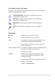
Conventions used in this guide To make sure that you perform certain tasks properly, take note of the following symbols used throughout this manual. DANGER/WARNING: Information to prevent injury to yourself when trying to complete a task. CAUTION: Information to prevent damage to the components when trying to complete a task. IMPORTANT: Instructions that you MUST follow to complete a task. NOTE: Tips and additional information to help you complete a task.
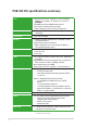
P5B-VM DO specifications summary CPU LGA775 socket for Intel® Quad-core / Core™2 Extreme/ ���� Core™2 Duo / Pentium® D / Pentium® 4 / Celeron® D ��������� processor Compatible with Intel® 05B/05A/06 processors Intel® Hyper-Threading Technology ready * Refer to www.asus.com for Intel CPU support list Chipset Intel® Q965 / ICH8DO with Intel® Active Management Technology System Bus 1066 / 800 / 533 MHz Memory 4 x DIMM, max.
P5B-VM DO specifications summary USB 10 x USB 2.0 ports (6 ports at mid-board, 4 ports at back panel) ASUS Features ASUS Quiet Thermal Solution: - ASUS Advanced Q-Fan ASUS Crystal Sound - Noise Filter ASUS EZ DIY: - ASUS Q-Connector - ASUS CrashFree BIOS 3 - ASUS EZ Flash 2 Other Features ASUS MyLogo 2 ASUS C.P.R.
P5B-VM DO specifications summary BIOS Features 16 Mb Flash ROM, AMI BIOS, PnP, DMI 2.0, WfM2.0, SM BIOS 2.3, ACPI 2.0a, ASUS EZ Flash 2, ASUS CrashFree BIOS 3 Manageability WfM 2.0, DMI 2.0, WOL by PME, WOR by PME, PXE, RPL Support CD Contents Drivers ASUS PC Probe II ASUS Update Anti-virus software (OEM version) Form Factor uATX form factor: 9.6” x 9.6” (24.4 cm x 24.4 cm) *Specifications are subject to change without notice.
This chapter describes the motherboard features and the new technologies it supports.
1.1 Welcome! Thank you for buying an ASUS® P5B-VM DO motherboard! The motherboard delivers a host of new features and latest technologies, making it another standout in the long line of ASUS quality motherboards! Before you start installing the motherboard, and hardware devices on it, check the items in your package with the list below. 1.2 Package contents Check your motherboard package for the following items.
Intel® Q965 Express Chipset The Intel® Q965 Express Chipset provides all business wth more effective costs management, safer computing environmrnt, and deploys more responsive PCs. It features the integrated graphics engine, Intel® Graphics Media Accelerator 3000, and Intel® Active Management Technology, both of which provide advancements in manageability, graphics, stability, data protection, and optimizations to support the most advanced business operating systems.
Dual RAID solution The Intel® ICH8DO chipset incorporates six Serial ATA connectors with high performance RAID 0, 1, 5 and 10 functions. The JMicron controller provides another two Serial ATA connectors for RAID 0, 1, and JBOD functions. Making this motherboard an ideal solution to enhance hard disk performance and data back up protection without the cost of add-on cards. See page 1-34 and 1-35 for details.
ASUS EZ DIY ASUS EZ DIY feature collection provides you easy ways to install computer components, update the BIOS or back up your favorite settings. ASUS Q-Connector ASUS Q-Connector allows you to easily connect or disconnect the chassis front panel cables to the motherboard. This unique module eliminates the trouble of connecting the system panel cables one at a time and avoiding wrong cable connections. See page 1-41 for details.
1.4 Before you proceed Take note of the following precautions before you install motherboard components or change any motherboard settings. • Unplug the power cord from the wall socket before touching any component. • Use a grounded wrist strap or touch a safely grounded object or a metal object, such as the power supply case, before handling components to avoid damaging them due to static electricity. • Hold components by the edges to avoid touching the ICs on them.
1.5 Motherboard overview Before you install the motherboard, study the configuration of your chassis to ensure that the motherboard fits into it. Make sure to unplug the power cord before installing or removing the motherboard. Failure to do so can cause you physical injury and damage motherboard components. 1.5.1 Placement direction When installing the motherboard, make sure that you place it into the chassis in the correct orientation.
1.5.3 Motherboard layout 24.5cm (9.6in) PS/2KBMS T: Mouse B: Keyboard PWR_FAN CHA_FAN CPU_FAN KBPWR 24.5cm (9.
1.5.4 Layout contents Slots Page 1. DDR2 DIMM slots 1-18 2. PCI slots 1-27 3. PCI Express x 4 slot 1-27 4. PCI Express x16 slot 1-27 Jumper Page 1. Clear RTC RAM (3-pin CLRTC) 1-28 2. Keyboard power (3-pin KBPWR) 1-29 Rear panel connectors Page 1. PS/2 mouse port (green) 1-30 2. Parallel port 1-30 3. IEEE 1394a port 1-30 4. LAN (RJ-45) port 1-30 5. Rear Speaker Out port (black) 1-30 6. Center/Subwoofer port (orange) 1-30 7. Line In port (light blue) 1-30 8.
1-10 Internal connectors Page 1. Floppy disk drive connector (34-1 pin FLOPPY) 1-32 2. Digital Audio connector (4-1 pin SPDIF_OUT) 1-32 3. IDE connector (40-1 pin PRI_IDE) 1-33 4. ICH8DO Serial ATA connectors (7-pin SATA1 [red], SATA2 [red], SATA3 [red], SATA4 [red], SATA5 [black], SATA6 [black]) 1-34 5. IEEE 1394a port connector (10-1 pin IE1394_2) 1-34 6. JMicron® JMB363 Serial ATA RAID connector (7-pin SATA_RAID1) 1-35 7. TPM connector (20-1 pin TPM_SLOT) 1-35 8.
1.6 Central Processing Unit (CPU) The motherboard comes with a surface mount LGA775 socket designed for the Intel® Core™2 Extreme/Core™2 Duo/Pentium® D/Pentium® 4 and Celeron® D processors. • Make sure the AC power is off before you install the CPU. • Upon purchase of the motherboard, make sure that the PnP cap is on the socket and the socket contacts are not bent.
1.6.1 Installing the CPU To install a CPU: Locate the CPU socket on the motherboard. R P5B-VM DO 1. P5B-VM DO CPU socket 775 Before installing the CPU, make sure that the cam box is facing towards you and the load lever is on your left. 2. Press the load lever with your thumb (A), then move it to the left (B) until it is released from the retention tab. Retention tab Load lever A PnP cap B This side of the socket box should face you.
4. Lift the load plate with your thumb and forefinger to a 100º angle (A), then push the PnP cap from the load plate window to remove (B). B A Load plate Alignment key 5. Position the CPU over the socket, making sure that the gold triangle is on the bottom‑left corner of the socket then fit the socket alignment key into the CPU notch. CPU notch Gold triangle mark The CPU fits in only one correct orientation.
1.6.2 Installing the CPU heatsink and fan The Intel LGA775 processor requires a specially designed heatsink and fan assembly to ensure optimum thermal condition and performance. ® • When you buy a boxed Intel® processor, the package includes the CPU fan and heatsink assembly. If you buy a CPU separately, make sure that you use only Intel®‑certified multi‑directional heatsink and fan. • Your Intel® LGA775 heatsink and fan assembly comes in a push-pin design and requires no tool to install.
2. Push down two fasteners at a time in a diagonal sequence to secure the heatsink and fan assembly in place. B A A 3. A B B A B Connect the CPU fan cable to the connector on the motherboard labeled CPU_FAN. GND CPU FAN PWR CPU FAN IN CPU FAN PWM R P5B-VM DO CPU_FAN P5B-VM DO CPU Fan Connector Do not forget to connect the CPU fan connector! Hardware monitoring errors can occur if you fail to plug this connector.
1.6.3 Uninstalling the CPU heatsink and fan To uninstall the CPU heatsink and fan: 1. 2. 3. 4. 1-16 Disconnect the CPU fan cable from the connector on the motherboard. Rotate each fastener counterclockwise. Pull up two fasteners at a time in a diagonal sequence to disengage the heatsink and fan assembly from the motherboard. A B B A B A A B Carefully remove the heatsink and fan assembly from the motherboard.
5. Rotate each fastener clockwise to ensure correct orientation when reinstalling. Narrow end of the groove The narrow end of the groove should point outward after resetting. (The photo shows the groove shaded for emphasis.) Refer to the documentation in the boxed or stand-alone CPU fan package for detailed information on CPU fan installation.
1.7 System memory 1.7.1 Overview The motherboard comes with four Double Data Rate 2 (DDR2) Dual Inline Memory Modules (DIMM) sockets. A DDR2 module has the same physical dimensions as a DDR DIMM but has a 240-pin footprint compared to the 184-pin DDR DIMM. DDR2 DIMMs are notched differently to prevent installation on a DDR DIMM socket.
• You may install varying memory sizes in Channel A and Channel B. The system maps the total size of the lower-sized channel for the dual-channel configuration. Any excess memory from the higher-sized channel is then mapped for single-channel operation. • Always install DIMMs with the same CAS latency. For optimum compatibility, it is recommended that you obtain memory modules from the same vendor.
P5B-VM DO Motherboard Qualified Vendors Lists (QVL) DDR2-800MHz capability Vendor Chip No.
P5B-VM DO Motherboard Qualified Vendors Lists (QVL) DDR2-667MHz capability Size Vendor Chip No.
P5B-VM DO Motherboard Qualified Vendors Lists (QVL) DDR2-553 MHz capability Size Vendor Chip No.
1.7.3 Installing a DIMM Unplug the power supply before adding or removing DIMMs or other system components. Failure to do so can cause severe damage to both the motherboard and the components. 2 To install a DIMM: 1. 2. 3. 3 Unlock a DIMM socket by pressing the retaining clips outward. Align a DIMM on the socket such that the notch on the DIMM matches the break on the socket.
1.8 Expansion slots In the future, you may need to install expansion cards. The following sub‑sections describe the slots and the expansion cards that they support. Make sure to unplug the power cord before adding or removing expansion cards. Failure to do so may cause you physical injury and damage motherboard components. 1.8.1 Installing an expansion card To install an expansion card: 1. 2. 3. 4. 5. 6.
1.8.
IRQ assignments for this motherboard A 1-26 B C D E F G H PCI Slot 1 shared — — — — — — — PCI Slot 2 — shared — — — — — — PCIE x 16_1 shared — — — — — — — PCIE x 4_1 shared — — — — — — — Onboard ESATA, SATA_RAID shared — — — — shared — — Onboard PRI_IDE shared — — — — — — — Onboard HD Audio (AD1988) — — — — — — shared — Onboard GbEthernet (82566DM) — shared — — — — — — USB 2.0 EHCI#1 — — — — — — — shared USB 2.
1.8.4 PCI slots The PCI slots support cards such as a LAN card, SCSI card, USB card, and other cards that comply with PCI specifications. The figure shows a LAN card installed on a PCI slot. 1.8.5 PCI Express x4 slot This motherboard supports PCI Express x4 network cards, SCSI cards and other cards that comply with the PCI Express specifications. The following figure shows a network card installed on the PCI Express x4 slot. 1.8.
1.9 1. Jumper Clear RTC RAM (CLRTC) This jumper allows you to clear the Real Time Clock (RTC) RAM in CMOS. You can clear the CMOS memory of date, time, and system setup parameters by erasing the CMOS RTC RAM data. The onboard button cell battery powers the RAM data in CMOS, which include system setup information such as system passwords. To erase the RTC RAM: 1. Turn OFF the computer and unplug the power cord. 2. Remove the onboard battery. 3. Move the jumper cap from pins 1-2 (default) to pins 2-3.
2. Keyboard power (3-pin KBPWR) This jumper allows you to enable or disable the keyboard wake-up feature. Set this jumper to pins 2-3 (+5VSB) to wake up the computer when you press a key on the keyboard (the default is the Space Bar). This feature requires an ATX power supply that can supply at least 1A on the +5VSB lead, and a corresponding setting in the BIOS.
1.10 Connectors 1.10.1 Rear panel connectors 1 3 2 4 56 7 8 9 1. 15 13 14 12 11 PS/2 mouse port (green). This port is for a PS/2 mouse. 2. 10 Parallel port. This 25-pin port connects a parallel printer, a scanner, or other devices. 3. IEEE 1394a port. This 6-pin IEEE 1394a port provides high-speed connectivity for audio/video devices, storage peripherals, PCs, or portable devices. 4. LAN (RJ-45) port.
Refer to the audio configuration table below for the function of the audio ports in 2, 4, 6, or 8-channel configuration. Audio 2, 4, 6, or 8-channel configuration Port Headset 2-channel 4-channel Lime Line Out Front Speaker Out Front Speaker Out Front Speaker Out Orange – – Center/Subwoofer Center/Subwoofer – – Side Speaker Out Light Blue Line In Pink Mic In Black – Gray 11.
1.10.2 1. Internal connectors Floppy disk drive connector (34-1 pin FLOPPY) This connector is for the provided floppy disk drive (FDD) signal cable. Insert one end of the cable to this connector, then connect the other end to the signal connector at the back of the floppy disk drive. Pin 5 on the connector is removed to prevent incorrect cable connection when using a FDD cable with a covered Pin 5. R P5B-VM DO FLOPPY PIN 1 NOTE: Orient the red markings on the floppy ribbon cable to PIN 1.
3. IDE connector (40-1 pin PRI_EIDE) The onboard IDE connector is for the Ultra DMA 133/100/66 signal cable. There are three connectors on each Ultra DMA 133/100/66 signal cable: blue, black, and gray. Connect the blue connector to the motherboard’s IDE connector, then select one of the following modes to configure your device.
4.
6. JMicron JMB363® Serial ATA RAID connector (7-pin SATA_RAID1) This connector is for a Serial ATA signal cable. This connector supports a Serial ATA hard disk drive, which you can combine with an external Serial ATA hard disk drive to configure for RAID via the unboard Serial ATA RAID controller. R P5B-VM DO The JMicron controller mode item in the BIOS is set to [BASIC] by default. When set to [RAID], this item allows you to use the connectors to build a RAID set. See section “2.4.
USB connectors (10-1 pin USB56, USB 78, USB910) These connectors are for USB 2.0 ports. Connect the USB module cable to any of these connectors, then install the module to a slot opening at the back of the system chassis. These USB connectors comply with USB 2.0 specification that supports up to 480 Mbps connection speed. USB+5V USB_P10USB_P10+ GND NC USB+5V USB_P9USB_P9+ GND USB910 USB+5V USB_P7USB_P7+ GND P5B-VM DO USB 2.
10. CPU, chassis, and power fan connectors (4-pin CPU_FAN, 3-pin CHA_FAN, 3-pin CHA_FAN2, 3-pin PWR_FAN) The fan connectors support cooling fans of 350 mA ~ 2000 mA (24 W max.) or a total of 1 A ~ 7 A (84 W max.) at +12V. Connect the fan cables to the fan connectors on the motherboard, making sure that the black wire of each cable matches the ground pin of the connector. Do not forget to connect the fan cables to the fan connectors.
12. Chassis intrusion connector (4-1 pin CHASSIS) This connector is for a chassis-mounted intrusion detection sensor or switch. Connect one end of the chassis intrusion sensor or switch cable to this connector. The chassis intrusion sensor or switch sends a high-level signal to this connector when a chassis component is removed or replaced. The signal is then generated as a chassis intrusion event.
14. ATX power connectors (24-pin EATXPWR, 4-pin EATX12V) These connectors are for ATX power supply plugs. The power supply plugs are designed to fit these connectors in only one orientation. Find the proper orientation and push down firmly until the connectors completely fit.
15. System panel connector (20-8 pin PANEL) This connector supports several chassis-mounted functions.
Q-Connector (system panel) ASUS Q-Connector allows you to easily to connect the chassis front panel cables to the motherboard. Perform these steps to install ASUS Q-Connector. Step1. Connect the front panel cables to their respective connectors on the ASUS QConnector. Refer to the labels on the Q-Connector for proper connection and pin definition. Step2. Carefully connect the ASUS Q-Connector to the System panel connector.
1-42 Chapter 1: Product introduction
This chapter tells how to change the system settings through the BIOS Setup menus. Detailed descriptions of the BIOS parameters are also provided.
2.1 Managing and updating your BIOS The following utilities allow you to manage and update the motherboard Basic Input/Output System (BIOS) setup. 1. ASUS EZ Flash 2 (Updates the BIOS using a floppy disk or USB flash disk.) 3. ASUS CrashFree BIOS 3 (Updates the BIOS using a bootable floppy, USB Flash disk, or the motherboard support CD when the BIOS file fails or gets corrupted.) 2. 4. ASUS AFUDOS (Updates the BIOS in DOS mode using a bootable floppy disk.
2. Copy the original or the latest motherboard BIOS file to the bootable floppy disk. 2.1.2 ASUS EZ Flash 2 utility The ASUS EZ Flash 2 feature allows you to update the BIOS without having to go through the long process of booting from a floppy disk and using a DOS‑based utility. The EZ Flash 2 utility is built-in the BIOS chip so it is accessible by pressing + during the Power-On Self-Test (POST). To update the BIOS using EZ Flash 2: 1. 2. 3. Visit the ASUS website (www.asus.
• • 2.1.3 This function can support devices such as USB flash disk, or floppy disk with FAT 32/16 format only. Do not shut down or reset the system while updating the BIOS to prevent system boot failure! AFUDOS utility The AFUDOS utility allows you to update the BIOS file in DOS environment using a bootable floppy disk with the updated BIOS file. This utility also allows you to copy the current BIOS file that you can use as backup when the BIOS fails or gets corrupted during the updating process.
Updating the BIOS file To update the BIOS file using the AFUDOS utility: 1. Visit the ASUS website (www.asus.com) and download the latest BIOS file for the motherboard. Save the BIOS file to a bootable floppy disk. Write the BIOS filename on a piece of paper. You need to type the exact BIOS filename at the DOS prompt. 2. 3. Copy the AFUDOS utility (afudos.exe) from the motherboard support CD to the bootable floppy disk you created earlier.
2.1.4 ASUS CrashFree BIOS 3 utility The ASUS CrashFree BIOS 3 is an auto recovery tool that allows you to restore the BIOS file when it fails or gets corrupted during the updating process. You can update a corrupted BIOS file using the motherboard support CD, the USB flash disk, or the floppy disk that contains the updated BIOS file. • Prepare the motherboard support CD, the USB flash disk, or the floppy disk containing the updated motherboard BIOS before using this utility.
Recovering the BIOS from the support CD To recover the BIOS from the support CD: 1. Remove any floppy disk from the floppy disk drive, then turn on the system. 3. The utility displays the following message and automatically checks the floppy disk for the original or updated BIOS file. 2. Insert the support CD to the optical drive. Bad BIOS checksum. Starting BIOS recovery... Checking for floppy...
2.1.5 • Only the USB flash disk with FAT 32/16 format and single partition can support ASUS CrashFree BIOS 3. The device size should be smaller than 8GB. • DO NOT shut down or reset the system while updating the BIOS! Doing so can cause system boot failure! ASUS Update utility The ASUS Update is a utility that allows you to manage, save, and update the motherboard BIOS in Windows® environment.
Updating the BIOS through the Internet To update the BIOS through the Internet: 1. Launch the ASUS Update utility from the Windows® desktop by clicking Start > Programs > ASUS > ASUSUpdate > ASUSUpdate. The ASUS Update main window appears. 2. Select Update BIOS from the Internet option from the drop‑down menu, then click Next. ASUS P5B-VM DO 3. Select the ASUS FTP site nearest you to avoid network traffic, or click Auto Select. Click Next.
4. 5. From the FTP site, select the BIOS version that you wish to download. Click Next. Follow the screen instructions to complete the update process. The ASUS Update utility is capable of updating itself through the Internet. Always update the utility to avail all its features. Updating the BIOS through a BIOS file To update the BIOS through a BIOS file: 1. 2. 3. 4. 2-10 Launch the ASUS Update utility from the Windows® desktop by clicking Start > Programs > ASUS > ASUSUpdate > ASUSUpdate.
2.2 BIOS setup program This motherboard supports a programmable firmware chip that you can update using the provided utility described in section “2.1 Managing and updating your BIOS.” Use the BIOS Setup program when you are installing a motherboard, reconfiguring your system, or prompted to“Run Setup.” This section explains how to configure your system using this utility. Even if you are not prompted to use the Setup program, you can change the configuration of your computer in the future.
2.2.1 BIOS menu screen Menu items Main Menu bar Advanced Power Configuration fields BIOS SETUP UTILITY Boot Tools Exit System Time [17:20:30] System Date [Thu 05/22/2006] Legacy Diskette A [1.44M, 3.5 in] SATA SATA SATA SATA SATA SATA 1 2 3 4 5 6 General help :[Not :[Not :[Not :[Not :[Not :[Not IDE Configuration System Information Detected] Detected] Detected] Detected] Detected] Detected] Use [ENTER], [TAB] or [SHIFT-TAB] to select a field. Use [+] or [-] to configure system Time.
2.2.4 Menu items The highlighted item on the menu bar displays the specific items for that menu. For example, selecting Main shows the Main menu items. System Time System Date Legacy Diskette A The other items (Advanced, Power, Boot, Tool, and Exit) on the menu bar have their respective menu items. 2.2.5 Sub-menu items SATA SATA SATA SATA SATA SATA 1 2 3 4 5 6 Use [ENTER], [TAB], or [SHIFT-TAB] to select a field. [06:22:54] [Fri 05/04/2006] [1.44M, 3.
2.3 Main menu When you enter the BIOS Setup program, the Main menu screen appears, giving you an overview of the basic system information. Refer to section “2.2.1 BIOS menu screen” for information on the menu screen items and how to navigate through them. Main Advanced Power BIOS SETUP UTILITY Boot Tools Exit System Time [17:20:30] System Date [Thu 05/22/2006] Legacy Diskette A [1.44M, 3.
2.3.4 SATA1-6 While entering Setup, the BIOS automatically detects the presence of IDE devices. There is a separate sub-menu for each IDE device. Select a device item then press to display the IDE device information. SATA 1 Device Select the type of device connected to the system.
PIO Mode [Auto] Selects the PIO mode. Configuration options: [Auto] [0] [1] [2] [3] [4] DMA Mode [Auto] Selects the DMA mode. Configuration options: [Auto] [SWDMA0] [SWDMA1] [SWDMA2] [MWDMA0] [MWDMA1] [MWDMA2] [UDMA0] [UDMA1] [UDMA2] [UDMA3] [UDMA4] [UDMA5] SMART Monitoring [Auto] Sets the Smart Monitoring, Analysis, and Reporting Technology. Configuration options: [Auto] [Disabled] [Enabled] 32Bit Data Transfer [Enabled] Enables or disables 32-bit data transfer.
If you want to use the Serial ATA hard disk drives as Parallel ATA physical storage devices, keep the defaul setting [IDE]. If you want the Serial ATA hard disk drives to use the Advanced Host Controller Interface (AHCI), set this item to [AHCI]. Hard Disk Write Protect [Disabled] Allows you to enable to disable the hard disk write protection. This will be effective only if device is accessed through BIOS.
2.4 Advanced menu The Advanced menu items allow you to change the settings for the CPU and other system devices. Take caution when changing the settings of the Advanced menu items. Incorrect field values can cause the system to malfunction. Adjust system frequency/voltage Jumperfree Configuration USB Configuration TPM Configuration CPU Configuration Chipset Onboard Devices Configuration PCIPnP 2.4.
FSB/CPU External Frequency Synchronization Front Side Bus CPU External Frequency FSB 1066 266 MHz FSB 800 200 MHz FSB 533 133 MHz DRAM Frequency [Auto] Allows you to set the DDR2 operating frequency. Configuration options: Available DRAM frequency options in various FSB settings FSB Configuration options Auto DDR2533 DDR2667 DDR2800 DDR2889* DDR21067* FSB 1066 • • • • • • FSB 800 • • • • * Provided for overclocking purpose only.
2.4.2 USB Configuration The items in this menu allow you to change the USB-related features. Select an item then press to display the configuration options. USB Configuration Module Version - 2.24.0-11.4 USB Devices Enabled: None Enables support for legacy USB. AUTO option disables legacy support if no USB devices are connected. Legacy USB Support [Auto] Port 64/60 Emulation [Disabled] USB 2.
2.4.3 TPM Configuration The items in this menu allow you to set the TPM (Trusted Platform Module) features. Select an item then press to display the configuration options. TPM Configuration Execute TPM Command [Last setting] TPM Enable/Disable Status [No State] TPM Owner Status [No State] Enable (Activate)/ Disable (Deactivate) Command to TPM Execute TPM Command [Last setting] Allows you to enable or disable the TPM security chip.
2.4.4 CPU Configuration The items in this menu show the CPU-related information that the BIOS automatically detects. Advanced BIOS SETUP UTILITY Configure advanced CPU settings Module Version: 3D.04 Manufacturer: Intel Brand String: Genuine Intel(R) CPU 2.93GHz Frequency : 2.
Vanderpool Technology [Enabled] Configuration options: [Enabled] [Disabled] CPU TM function [Enabled] Configuration options: [Disabled] [Enabled] Execute Disable Bit [Enabled] Allows you to enable or disable the No-Execution Page Protection Technology. Setting this item to [Disabled] forces the XD feature flag to always return to zero (0).
2.4.5 Chipset The Chipset menu allows you to change the advanced chipset settings. Select an item then press to display the sub-menu. Advanced Chipset Settings WARNING: Setting wrong values in below sections may cause the system to malfunction. Configure North Bridge features.
DRAM RAS# to CAS# Delay [6 DRAM Clocks] Controls the latency between the DDR SDRAM active command and the read/write command. Configuration options: [3 DRAM Clocks]~[6 DRAM Clocks] DRAM RAS# Precharge [6DRAM Clocks] Controls the idle clocks after issuing a precharge command to the DDR SDRAM.
vPro Technology Configuration With the support of the Intel® vPro™ Technology, the items in this menu allow you to configure the Intel® Management Engine (ME) subsystem and enable the ����� Intel® Active������������������������������������������������������������������������� Management Technology. Select an item then press to display the configuration options. To enable the following functions, you must ����������������� install the Intel® Management Engine Interface. See page 3-3 for details.
ME-KT [Disabled] When set to [Enabled], the KT function helps redirect keyboard and POST message to the remote management console and thus facilitates the control of the client machine through the network. Configuration options: [Disabled] [Enabled] Configure Intel AMT Parameters Intel AMT Support [Enabled] Allows you to enable or disable the Intel® AMT (Active Management Technology).
Onboard 1394 Cotroller [Enabled] ��������� Allows you to enable or disable the onboard IEEE 1394 controller. Configuration options: [Enabled] [Disabled] Onboard LAN [Enabled] Allows you to enable or disable the onboard LAN controller. Configuration options: [Enabled] [Disabled] LAN Option ROM [Disabled] Configuration options: [Disabled] [Enabled] JMicron SATA/PATA Controller [Enabled] Allows you to enable or disable the JMicron SATA/PATA controller.
2.4.7 PCI PnP The PCI PnP menu items allow you to change the advanced settings for PCI/PnP devices. The menu includes setting IRQ and DMA channel resources for either PCI/PnP or legacy ISA devices, and setting the memory size block for legacy ISA devices. Take caution when changing the settings of the PCI PnP menu items. Incorrect field values can cause the system to malfunction. Advanced PCI/PnP Settings WARNING: Setting wrong values in below sections may cause system to malfunction.
IRQ-xx assigned to [PCI Device] When set to [PCI Device], the specific IRQ is free for use of PCI/PnP devices. When set to [Reserved], the IRQ is reserved for legacy ISA devices. Configuration options: [PCI Device] [Reserved] 2.5 Power menu The Power menu items allow you to change the settings for the Advanced Power Management (APM). Select an item then press to display the configuration options. Suspend Mode [Auto] Repost Video on S3 Resume [No] ACPI 2.0 Support [ACPI v1.
2.5.5 APM Configuration APM Configuration Restore on AC Power Loss [Power Off] Power On By RTC Alarm [Disabled] Power On By External Modems [Disabled] Power On By PCI Devices [Disabled] Power On By Onboard Lan [Disabled] Power On By PCIE Devices [Disabled] Power On By PS/2 Keyboard [Disabled] Power On By PS/2 Mouse [Disabled] to select whether or not to restart the system after AC power loss.
Power On By PCIE Devices [Disabled] Allows you to enable or disable the PCIE devices to generate a wake event. Configuration options: [Disabled] [Enabled] Power On By PS/2 Keyboard [Disabled] Allows you to use specific keys on the keyboard to turn on the system. This feature requires an ATX power supply that provides at least 1A on the +5VSB lead.
Power Fan Speed [xxxxRPM] or [Ignored] / [N/A] The onboard hardware monitor automatically detects and displays the chasis fan speed in rotations per minute (RPM). If the fan is not connected to the motherboard, the field shows N/A. VCORE Voltage, 3.3V Voltage, 5V Voltage, 12V Voltage The onboard hardware monitor automatically detects the voltage output through the onboard voltage regulators. Select [Ignored] if you do not wish to display these items.
2.6.2 Boot Settings Configuration BIOS SETUP UTILITY Boot Boot Settings Configuration Quick Boot [Enabled] Full Screen Logo [Enabled] AddOn ROM Display Mode [Force BIOS] Bootup Num-Lock [On] PS/2 Mouse Support [Auto] Wait For ‘F1’ If Error [Enabled] Hit ‘DEL’ Message Display [Enabled] Interrupt 19 Capture [Disabled] Allows BIOS to skip certain tests while booting. This will decrease the time needed to boot the system.
2.6.3 Security The Security menu items allow you to change the system security settings. Select an item then press to display the configuration options. 4.6.1 BIOS SETUP UTILITY Boot Device PriorityBoot Security Settings Supervisor Password User Password : Not Installed : Not Installed to change password. again to disabled password. Change Supervisor Password Change User Passward Change Supervisor Password Select this item to set or change the supervisor password.
After you have set a supervisor password, the other items appear to allow you to change other security settings. 4.6.1 BIOS SETUP UTILITY Boot Device PriorityBoot Security Settings Supervisor Password User Password : Not Installed : Not Installed to change password. again to disabled password.
Password Check [Setup] When set to [Setup], BIOS checks for user password when accessing the Setup utility. When set to [Always], BIOS checks for user password both when accessing Setup and booting the system. Configuration options: [Setup] [Always] 2.7 Tools menu The Tools menu items allow you to configure options for special functions. Select an item then press to display the sub-menu. ASUS EZ Flash 2 2.7.1 Press ENTER to run the utility to select and update BIOS.
2.8 Exit menu The Exit menu items allow you to load the optimal or failsafe default values for the BIOS items, and save or discard your changes to the BIOS items. Main Advanced Power Exit Options Exit & Save Changes Exit & Discard Changes Discard Changes Load Setup Defaults BIOS SETUP UTILITY Boot Tools Exit Exit system setup after saving the changes. F10 key can be used for this operation. Pressing does not immediately exit this menu.
This chapter describes the contents of the support CD that comes with the motherboard package.
3.1 Installing an operating system This motherboard supports Windows® 2000/XP/64-bit XP operating systems (OS). Always install the latest OS version and corresponding updates to maximize the features of your hardware. 3.2 • Motherboard settings and hardware options vary. Use the setup procedures presented in this chapter for reference only. Refer to your OS documentation for detailed information.
3.2.2 Drivers menu The drivers menu shows the available device drivers if the system detects installed devices. Install the necessary drivers to activate the devices. ASUS InstAll-Drivers Installation Wizard Installs the ASUS InstAll-Drivers installation wizard. Intel Chipset Inf Update Program Installs the Intel® chipset inf update program. Intel Graphics Accelerator Driver Installs the Intel® graphics accelerator driver.
3.2.3 Utilities menu The Utilities menu shows the applications and other software that the motherboard supports. ASUS InstAll-Installation Wizard for Utilities Install the ASUS InstAll-Installation Wizard. ASUS PC Probe II This smart utility monitors the fan speed, CPU temperature, and system voltages, and alerts you of any detected problems. This utility helps you keep your computer in healthy operating condition.
3.2.4 Make Disk menu The Make Disk menu contains items to create JMicron® JMB36X or Intel® ICH8 RAID/AHCI driver disk. Make JMicron JMB36X 32/64bit RAID/AHCI Driver Allows you to create a JMicron® JMB36X 32/64bit RAID/AHCI driver. Make Intel® ICH8 32/64bit RAID/AHCI Driver Allows you to create a Intel® ICH8 32/64bit RAID/AHCI driver disk.
3.2.5 Manuals menu The Manuals menu contains a list of supplementary user manuals. Click an item to open the folder of the user manual. Most user manual files are in Portable Document Format (PDF). Download the Adobe® Acrobat® Reader from www.adobe.com if you do not have one. 3.2.6 ASUS Contact information Click the Contact tab to display the ASUS contact information. You can also find this information on the inside front cover of this user guide.
3.2.7 Other information The icons on the top right corner of the screen give additional information on the motherboard and the contents of the support CD. Click an icon to display the specified information. Motherboard Info Displays the general specifications of the motherboard. Browse this CD Displays the support CD contents in graphical format.
Technical support form Displays the ASUS Technical Support Request Form that you have to fill out when requesting technical support. Filelist Displays the contents of the support CD and a brief description of each in text format.