Motherboard P5G43-V WS 用戶手冊
C5333 1.00 版 2010 年 3 月發行 版權所有‧不得翻印 © 2010 華碩電腦 本產品的所有部分,包括配件與軟件等,其相關知識產權等歸華碩電腦公 司(以下簡稱華碩)或授權華碩使用的相關主體所有,未經權利主體許可, 不得任意地仿製、拷貝、摘抄或轉譯。本用戶手冊沒有任何型式的擔保、立 場表達或其它暗示。若有任何因本用戶手冊或其所提到之產品信息,所引起 直接或間接的數據流失、利益損失或事業終止,華碩及其所屬員工恕不為其 擔負任何責任。除此之外,本用戶手冊所提到的產品規格及信息只作參考, 內容亦會隨時疏漏或升級,恕不另行通知。 下列因素導致的產品故障或損壞不在免費保修範圍內: A. 因天災(水災、火災、地震、雷擊、颱風等)、遇不可抗拒外力或人為 之操作使用不慎造成之損害。 B. 自 行拆裝、修理、或將產品送至非華碩認証之維修點進行檢測維 修。 C. 用 戶擅自或請第三人修改、修復、更改規格及安裝、添加、擴展非本 公司原廠銷售、授權或認可之配件所引起之故障與損壞。 D. 因用戶自行安裝軟件及設置不當所造成之使用問題及故障。 E. 計算機病毒所造成之問題及故障。 F.
目錄內容 目錄內容.........................................................................................................................iii 安全性須知................................................................................................................... vi 電氣方面的安全性........................................................................................... vi 操作方面的安全性........................................................................................... vi 關於這本用戶手冊........................................
目錄內容 1.8.6 PCI Express 2.0 x16 擴展卡插槽......................................... 1-21 1.9 跳線選擇區.................................................................................................... 1-22 1.10 元件與外圍設備的連接.......................................................................... 1-23 1.10.1 後側面板連接端口..................................................................... 1-23 1.10.2 音頻輸出/入設置........................................................................ 1-24 1.10.3 內部連接端口.......................
目錄內容 2.4.6 PCI 即插即用設備(PCI PnP).............................................. 2-23 2.5 電源管理(Power menu)..................................................................... 2-24 2.5.1 Suspend Mode [Auto]............................................................... 2-24 2.5.2 Repost Video on S3 Resume [No]....................................... 2-24 2.5.3 ACPI 2.0 Support [Disabled]................................................... 2-24 2.5.4 ACPI APIC Support [Enabled].....................................
安全性須知 電氣方面的安全性 • 為避免可能的電擊造成嚴重損害,在搬動電腦主機之前,請先將電腦電 源線暫時從電源插槽中拔掉。 • 當您要加入硬件設備到系統中或者要移除系統中的硬件設備時,請務必 先連接該設備的信號線,然後再連接電源線。可能的話,在安裝硬件設 備之前先拔掉電腦的電源(PSU)電源線。 • 當您要從主板連接或拔除任何的信號線之前,請確定所有的電源線已事 先拔掉。 • 在使用擴展卡之前,我們推薦您可以先尋求專業人士的協助。這些設備 有可能會干擾接地的迴路。 • 請確定電源(PSU)的電壓設置已調整到本國/本區域所使用的電壓標準 值。若您不確定您所屬區域的供應電壓值為何,那麼請就近詢問當地的 電力公司人員。 • 如果電源(PSU)已損壞,請不要嘗試自行修復。請將之交給專業技術服 務人員或經銷商來處理。 操作方面的安全性 • 在您安裝主板以及加入硬件設備之前,請務必詳加閱讀本手冊所提供的 相關信息。 • 在使用產品之前,請確定所有的排線、電源線都已正確地連接好。若您 發現有任何重大的瑕疵,請盡快聯絡您的經銷商。 • 為避免發生電氣短路情形,請務必將所有沒用到的螺絲、回形針及其他 零件
關於這本用戶手冊 產品用戶手冊包含了所有當您在安裝華碩 P5G43-V WS 主板時所需用到 的信息。 用戶手冊的編排方式 用戶手冊是由下面幾個章節所組成: • 第一章:產品介紹 您可以在本章節中發現諸多華碩所賦予 P5G43-V WS 主板的優異特 色。利用簡潔易懂的說明讓您能很快地掌握本主板的各項特性,當然, 在本章節中我們也會提及所有能夠應用在本主板的新技術。 另外,本章節亦提供所有您在安裝系統元件時必須完成的硬件安裝程 序。詳細內容有:處理器與內存安裝、跳線選擇區設置以及主板的各種 設備接口。 • 第二章:BIOS 程序設置 本章節描述如何使用 BIOS 設置程序中的每一個菜單項目來更改系統 的配置設置。此外也會詳加介紹 BIOS 各項設置值的使用時機與參數設 置。 • 第三章:軟件支持 您可以在本章節中找到所有包含在華碩驅動及應用程序光盤中的軟件 相關信息。 vii
提示符號 為了能夠確保您正確地完成主板設置,請務必注意下面這些會在本手冊中 出現的標示符號所代表的特殊含意。 警告:提醒您在進行某一項工作時要注意您本身的安全。 小心: 提 醒您在進行某一項工作時要注意勿傷害到電腦主板元 件。 重要: 此符號表示您必須要遵照手冊所描述之方式完成一項或多項 軟硬件的安裝或設置。 注意:提供有助於完成某項工作的訣竅和其他額外的信息。 跳線帽及圖標說明 主板上有一些小小的塑料套,裡面有金屬導線,可以套住選擇區的任二隻 針腳(Pin)使其相連而成一通路(短路),本手冊稱之為跳線帽。 有關主板的跳線帽使用設置,茲利用以下圖標說明。以下圖為例,欲設置 為「Jumper™ Mode」,需在選擇區的第一及第二隻針腳部份蓋上跳線帽, 本手冊圖標即以塗上底色代表蓋上跳線帽的位置,而空白的部份則代表空接 針。以文字表示為:[1-2]。 因此,欲設置為「JumperFree™ Mode」,以 右圖表示即為在「第二及第三隻針腳部份蓋上跳 線帽」,以文字表示即為:[2-3]。 1 2 Jumper Mode 2 3 Jumper Free (Default) 哪裡可以找到更多的產品信息 您
電子信息產品污染控制標示:圖中之數字為產品之環保使用 期限。只指電子信息產品中含有的有毒有害物質或元素不致發 生外洩或突變從而對環境造成污染或對人身、財產造成嚴重損 害的期限。 有毒有害物質或元素的名稱及含量說明標示: 有害物質或元素 部件名稱 鉛(Pb) 鎘(Cd) 汞(Hg) 六價鉻 (Cr(VI)) 多溴聯苯 (PBB) 多溴二苯醚 (PBDE) 印刷電路板及其電 子組件 × ○ ○ ○ ○ ○ 外部信號連接口及 線材 × ○ ○ ○ ○ ○ ○: 表示該有毒有害物質在該部件所有均質材料中的含量均在 SJ/T 113632006 標准規定的限量要求以下。 ×: 表示該有毒有害物質至少在該部件的某一均質材料中的含量超出 SJ/T 11363-2006 標准規定的限量要求,然該部件仍符合歐盟命令 2002/95/ EC 的規范。 備註:此產品所標示之環保使用期限,係指在一般正常使用狀況下。 ix
P5G43-V WS 規格列表 中央處理器 支持採用 LGA775 規格插槽的 Intel® Core™2 Extreme / Core™2 Quad / Core™2 Duo / Pentium® Extreme / Pentium® D / Pentium® 4 / Celeron® 處理器 兼容於 Intel® 05B/05A/06 處理器 支持 Intel® 新一代 45nm 多核心處理器 支持增強型 Intel SpeedStep® 技術(EIST) 支持 Intel® Hyper-Threading 技術 * 請訪問 www.asus.com.cn 取得最新 Intel 處理器 支持列表 芯片組 Intel® G43 Intel ICH10 支持 Intel® 高速內存存取技術 系統總線 1333/1066/800 MHz 內存 支持雙通道內存結構 4 組內存條插槽,使用符合 non-ECC unbufferred DDR2 1066(O.C.
P5G43-V WS 規格列表 華碩獨家功能 華碩 Q-Fan 3 智能溫控風扇技術 華碩免風扇設計 華碩 Q-Connector 集成式信號線接口 華碩 CrashFree BIOS 3 程序 華碩 EZ Flash 2 程序 華碩 AI Suite 其他功能 華碩 MyLogo2 個性化應用程序 後側面板設備連接端 口 1 x PS/2 鍵盤連接端口 1 x PS/2 鼠標連接端口 2 x RJ-45 網絡連接端口 4 x USB 2.0/1.1 連接端口 1 x D-Sub 顯示輸出連接端口 八聲道音頻 I/O 面板 內置 I/O 設備連接 端口 3 6 1 3 1 1 1 1 1 1 1 1 1 1 BIOS 功能 8Mb Flash ROM、AMI BIOS、PnP、DMI2.0、 WfM2.0、SM BIOS 2.5、ACPI 2.
xii
您可以在本章節中發現諸多華碩所賦 予本主板的優異特色,利用簡潔易懂的 說明,讓您能很快的掌握本主板的各項特 性,當然,在本章節我們也會提及所有能 夠應用在本主板的新產品技術。 1 產品介紹
1.1 歡迎加入華碩愛好者的行列! 再次感謝您購買此款華碩 P5G43-V WS 主板! 本主板的問世除了再次展現華碩對於主板一貫具備的高質量、高性能以 及高穩定度的嚴苛要求,同時也添加了許多新的功能以及大量應用在它身上 的最新技術,使得 P5G43-V WS 主板成為華碩優質主板產品線中不可多得 的閃亮之星。 在您拿到本主板包裝盒之後,請立即檢查下面所列出的各項標準配件是 否齊全。 1.
1.3 特殊功能 1.3.1 產品特寫 符合 Green ASUS 規範 本主板與其包裝盒皆符合歐盟關於使用有害物質的限制規範(RoHS)。 而這也正符合華碩對於創建友善環境,將對環境的影響降低至最少,製造可 回收且對用戶健康無害的產品包裝的企業願景一致。 支持 Intel® Core™2 Extreme / Core™2 Quad / Core™2 Duo 處理器 本主板支持採用最新 LGA775 封裝的 Intel Core™ 2 處理器。它同時 亦支持 Intel 45nm 多核心處理器。通過新一代 Intel Core™ 微結構技術與 1333/1066/800 MHz 的前端總線帶寬,Intel Core™ 2 處理器將是世界上 最具性能與運算速率的處理器。 支持雙通道 DDR2 1066(超頻)內存 本主板支持 DDR2 數據傳輸率技術,擁有 667/800/1066(超頻)MHz 的數據傳輸率,可以符合像是 3D 繪圖、多介質與網絡應用等更高的系統帶 寬需求。雙通道 DDR2 內存結構可讓您系統的內存帶寬倍增,可以顯著提升 您系統平台的性能,並降低帶寬的瓶頸。 PCIe 2.
支持 TPM 本主板支持 Trusted Platform Module(TPM)模塊,可通過高級加密/解 密與完整平台集成性的方式,提供更為強化的數據保全。TPM 功能符合 Windows Vista 的 BitLocker™ Drive 加密硬件需求,將可以提供更為安全 的工作環境。 1.3.
1.4 主板安裝前 主板以及擴展卡都是由許多精密複雜的集成電路元件、集成性芯片等所構 成。而這些電子性零件很容易因靜電的影響而導致損壞,因此,在您動手更改 主板上的任何設置之前,請務必先作好以下所列出的各項預防措施。 ‧ 在處理主板上的內部功能設置時,您可以先拔掉電腦的電源 線。 ‧ 為避免生成靜電,在拿取任何電腦元件時除了可以使用防靜電 手環之外,您也可以觸摸一個有接地線的物品或者金屬物品像 電源(PSU)外殼等。 ‧ 拿取集成電路元件時請盡量不要觸碰到元件上的芯片。 ‧ 在您移除任何一個集成電路元件後,請將該元件放置在絕緣墊 上以隔離靜電,或者直接放回該元件的絕緣包裝袋中保存。 ‧ 在您安裝或移除任何元件之前,請確認 ATX 電源(PSU)的 電源開關是切換到關閉(OFF)的位置,而最安全的做法是先 暫時拔出電源(PSU)的電源線,等到安裝/移除工作完成後再 將之接回。如此可避免因仍有電力殘留在系統中而嚴重損及主 板、外圍設備、元件等。 1.
2. USB 設備喚醒功能設置(3-pin USBPW03, USBPW47, USBPW89) 將本功能設為 +5V 時,您可以使用 USB 接口設備將電腦從 S1 睡眠 模式(中央處理器暫停、內存已刷新、整個系統處於低電力模式)中喚 醒。當本功能設置為 +5VSB 時,則表示可以從 S3 與 S4 睡眠模式( 未供電至中央處理器、內存延遲升級、電源(PSU)處於低電力模式) 中將電腦喚醒。 • 欲使用 USB 設備喚醒功能的 +5VSB 設置,您所使用的電源( PSU)必須能夠提供每個設備至少 500mA/+5VSB 的電力, 否則無法喚醒電腦系統。 • 無論電腦處於一般工作或是省電模式中,總電力消耗都不得超 過電源(PSU)的負荷能力(+5VSB)。 3.
1.5 主板概述 1.5.1 主板結構圖 關於面板連接插座與內部連接插座的相關信息,請參考「1.
1.5.2 主板元件說明 1-8 連接端口/開關與跳線選擇區/插槽 頁碼 1. 1-9 鍵盤喚醒功能設置(3-pin KBPWR) 2. USB 設備喚醒功能設置(3-pin USBPW03, USBPW47, USBPW89) 1-9 3. 主板電源插槽(24-pin EATXPWR, 4 -pin ATX12V) 1-37 4. LGA775 中央處理器 1-13 5. 系統內存 1-18 6. 中央處理器/機箱/電源(PSU) 風扇電源插槽(4-pin CPU_ FAN, 3-pin CHA_FAN1-3, 3-pin PWR_FAN) 1-34 7. ICH10 Serial ATA 設備連接插槽【紅色】(7-pin SATA1-6) 1-32 8. 電力指示燈(SB_PWR) 1-8 9. 輔助系統控制面板連接排針 (20-pin AUX_PANEL1) 1-39 10. 系統控制面板連接排針(20-8 pin PANEL) 1-38 11. CMOS 配置數據清除(3-pin CLRTC) 1-27 12.
1.5.3 主板的擺放方向 當您安裝主板到電腦主機機箱內時,務必確認安裝的方向是否正確。主板 上的 PS/2 鼠標/鍵盤接口、VGA 連接端口以及音頻插頭等的方向應是朝向 主機機箱的後方面板,而且您也會發現主機機箱後方面板會有相對應的預留 孔位。請參考下圖所示。 1.5.
1.
2. 以姆指壓下(A)固定扳手並將 其稍向左側推(B),這麼做可 使扳手脫離固定扣並鬆開 CPU 輔助安裝盒。 CPU 安裝盒上的保護蓋 是用以保護插槽上的接腳 之用,因此只有在 CPU 安裝妥當之後,才可將其 移除。 固定扣 A B 固定板手 3. 依箭頭方向拉起固定板手至 135 度角。 保護蓋 安全盒上蓋 4. 請用手指將 CPU 安裝盒的上蓋 掀起(4A),然後用手指從上 蓋內側的缺口將保護蓋推開移除 (4B)。 4B 4A 3 5.
6. 滴幾滴散熱膏至 CPU 與散熱鰭 片接觸的區域,並將其塗抹為一 均勻薄層。 某些散熱鰭片會預先塗上 散熱膏,若此,請跳過此 步驟。 散熱界面的材質具有毒性且不可食用。如果誤入眼睛或接觸皮膚, 請立即以清水沖洗,並尋求專業的醫療協助。 為避免污染散熱膏,請勿直接以手指塗抹散熱膏。 7.
1.6.2 安裝散熱片和風扇 Intel LGA775 處理器需要搭配安裝經過特殊設計的散熱片與風扇,方能 得到最佳的散熱性能。 • 若您所購買的是盒裝 Intel 處理器,則產品包裝中即已內含有一 組專用的散熱片與風扇;若您所購買的是散裝的處理器,請確 認您所使用的 CPU 散熱器已通過 Intel 的相關認證。 • 盒裝 Intel LGA775 處理器包裝中的散熱器與風扇採用下推式 固定扣具,因此無須使用任何工具進行安裝。 若您分別購買處理器散熱片與風扇,在安裝散熱片與風扇前,請先 確認散熱界面材質是否適用於處理器散熱片或處理器。 在安裝處理器的風扇和散熱片之前,請先確認主板已經安裝至機 箱上。 請依照下面步驟安裝處理器的散熱片和風扇: 1. 將散熱器放置在已安裝好的 CPU 上方,並確認主板上的四個孔位與 散熱器的四個扣具位置相吻合。 2.
3. 當風扇、散熱片以及支撐機構都已安裝完畢,接著請將風扇的電源線插 到主板上標示有「CPU_FAN」的電源插槽。 若您未連接 CPU_FAN 的電源插槽,可能將會導致啟動時 CPU 溫 度過熱並出現「Hardware monitoring errors」的信息。 1.6.3 卸除散熱器與風扇 請按照以下的步驟卸除散熱器和風扇: 1. 先將主板上連接 CPU 散熱器的 電源線從 CPU_FAN 上移除。 2. 將每個扣具上的旋鈕以逆時鐘方 向旋轉,鬆開散熱器固定扣具。 A B B 3. 依照順序將扣具扳離主板上的散 熱器插孔,採對角線方式移除, 例如:先移除 A,再移除 B;或 是先移除 B,再移除 A。 A B B A 4.
1.7 系統內存 1.7.
1.7.2 內存設置 您可以任意選擇使用 512MB、1GB 與 2GB 的 unbuffered non-ECC DDR2 內存條至本主板的內存插槽上。詳細安裝方式請參考本節中所提到的內存配 置方式進行安裝。 • 由於芯片組的運行方式之故,要將內存頻率維持在 DDR2 800 以上,您可以在 BIOS 程序設置中手動調整「DRAM Frequency」 項目中的內存頻率數值。請參考“2.4.
P5G43-V WS 主板合格供應商列表(QVL) DDR2-800MHz 供應商 型號 容量 SS/ DS 支持內存插槽 芯片廠牌 芯片型號 Timing 電壓 (隨選) B C Apacer 78.01GA0.9L5 1GB SS Apacer AM4B5808FEWS8E 5 - • • • Apacer 78.A1GA0.9L4 2GB DS Apacer AM4B5808FEWS8E 5 - • • • 1GB DS - - 4 1.9 • • • "BoxP/N:TWIN2X4096CORSAIR 6400C5(CM2X2048-6400C5) Ver3.1" 4GB(2 x 2GB) DS - - 5-5-5-18 1.80 • • • Crucial BL12864AA80A.8FE5(EPP) 1GB SS - - 4-4-4-12 2.0 • • • Crucial BL25664AA80A.
1.7.3 安裝內存條 安裝/移除內存條或其他的系統元件之前,請先暫時拔出電腦的電 源線。以避免一些會對主板或元件造成嚴重損壞的情況發生。 2 請依照下面步驟安裝內存條: 內存條缺口 1. 先將內存條插槽兩端的白色固定 卡扣扳開。 2. 將內存條的金手指對齊內存條插 槽的溝槽,並且在方向上要注意 金手指的缺口要對準插槽的凸起 點。 1 1 向外扳開插槽兩端的卡扣 由於 DDR2 DIMM 內存條金手指部份均有缺口設計,因此只能 以一個固定方向安裝到內存條插槽中。安裝時只需對準金手指與 插槽中的溝槽,再輕輕安裝內存條即可。請勿強制插入以免損及 內存條。 3 3. 最後緩緩將內存條插入插槽中, 若無錯誤,插槽兩端的白色卡扣 會因內存條安裝而自動扣到內存 條兩側的凹孔中。 卡扣會在內存條正確 安裝後自動扣上 1.7.4 取出內存條 請依照以下步驟取出內存條: 1. 同時壓下內存條插槽兩端白色的 固定卡扣以鬆開內存條。 在壓下固定卡扣取出內存 條的同時,您可以用手指 頭輕輕地扶住內存條,以 免跳出而損及內存條。 2 1 1 內存條缺口 2.
1.8 擴展插槽 為了因應未來會擴展系統性能的可能性,本主板提供了擴展插槽,在接下 來的次章節中,將會描述主板上這些擴展插槽的相關信息。 安裝/移除任何擴展卡之前,請暫時先將電腦的電源線拔出。如此 可免除因電氣殘留於電腦中而發生的意外狀況。 1.8.1 安裝擴展卡 請依照下列步驟安裝擴展卡: 1. 在安裝擴展卡之前,請先詳讀該擴展卡的使用說明,並且要針對該卡作 必要的硬件設置更改。 2. 鬆開電腦主機的機箱蓋並將之取出(如果您的主板已經放置在主機 內)。 3. 找到一個您想要插入新擴展卡的空置插槽,並以十字螺絲起子鬆開該插 槽位於主機背板的金屬擋板的螺絲,最後將金屬擋板移出。 4. 將擴展卡上的金手指對齊主板上的擴展槽,然後慢慢地插入槽中,並以 目視的方法確認擴展卡上的金手指已完全沒入擴展槽中。 5. 再用剛才鬆開的螺絲將擴展卡金屬擋板鎖在電腦主機背板以固定整張 卡。 6. 將電腦主機的機箱蓋裝回鎖好。 1.8.2 設置擴展卡 在安裝好擴展卡後,接著還須由於軟件設置來調整該擴展卡的相關設置。 1.
1.8.
1.8.4 PCI 擴展卡插槽 本主板配置 32 位的 PCI 擴展卡插槽,舉凡網卡、SCSI 卡、聲卡、USB 卡等符合 PCI 接口規格者,都可以使用在些 PCI 擴展卡插槽。 1.8.5 PCI Express x1 擴展卡插槽 本主板提供支持 x1 規格的 PCI Express 擴展卡插槽。 當使用 PCIe x1 擴展卡時,請先將該卡安裝在 PCIe x1 插槽,再 試著使用 PCIe x16 插槽。 1.8.6 PCI Express 2.0 x16 擴展卡插槽 本主板提供支持 x16 規格的 PCI Express 2.0 擴展卡插槽。這組插槽支持 安裝 PCI Express x16 顯卡且完全兼容於 PCI Express 規格。 PCI 插槽 PCI 插槽 PCIe x1 插槽 PCIe x1 插槽 PCIe x1 插槽 PCIe 2.
1.9 跳線選擇區 1. CMOS 配置數據清除(3-pin CLRTC) 內置在本主板上的開關讓您在後側面板上即可操作 clr CMOS 開關。 您可以由於清除 CMOS 配置數據以刪除 CMOS 內存中以及系統設置參 數等數據。在後側面板的 clr CMOS 配置清除開關可讓您輕鬆清除如系 統密碼等系統設置數據。 當想要清除配置數據時,請依照下列步驟進行: 1. 將 電腦關機,並將連接在主機後方的電源線拔除,然後按下後側面 板的 clr CMOS 開關。 2.
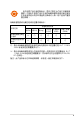
1.10 元件與外圍設備的連接 1.10.1 後側面板連接端口 後側面板連接端口 1. PS/2 鍵盤連接端口(紫色) 5. USB 2.0 設備連接端口(3 和 4) 2. LAN 2(RJ-45)網絡連接端口** 6. USB 2.0 設備連接端口(1 和 2) 3. LAN 1(RJ-45)網絡連接端口** 7. VGA 顯示連接端口 4. PS/2 鼠標連接端口(綠色) 8.
*** 二、四、六或八聲道音頻設置 耳機/二聲道揚 聲器輸出 四聲道揚聲器輸 出 六聲道揚聲器輸 出 八聲道揚聲器輸 出 淺藍色 聲音輸入端 聲音輸入端 聲音輸入端 聲音輸入端 草綠色 聲音輸出端 前置揚聲器輸出 前置揚聲器輸出 前置揚聲器輸出 粉紅色 麥克風輸入端 麥克風輸入端 麥克風輸入端 麥克風輸入端 橘色 – – 中央聲道/重低音 揚聲器輸出 中央聲道/重低 音揚聲器輸出 黑色 – 後置揚聲器輸出 後置揚聲器輸出 後置揚聲器輸出 灰色 – – - 側邊揚聲器輸出 接口 1.10.
連接立體聲揚聲器 連接 2.1 聲道揚聲器 連接 4.
連接 5.1 聲道揚聲器 連接 7.
1.10.3 內部連接端口 1. ICH10 Serial ATA 設備連接插槽【紅色】(7-pin SATA1-6) 這些插槽可支持使用 Serial ATA 排線來連接 Serial ATA 3Gb/s 硬 盤。Serial ATA 3Gb/s 硬盤可以向下兼容 Serial ATA 1.5Gb/s 規格的 硬盤。 注意:將 SATA 信號在線的直角 接口端(right angle side)連接在 SATA 設備上,或是將直角接口端安 裝至主板內置的 SATA 連接端口, 以避免造成與較大顯卡的衝突。 ‧ 這些插槽的默認值為 [Standard IDE],在 [Standard IDE] 模式 時,您可以將 Serial ATA 啟動或數據硬盤安裝在這些插槽上。 請參考「3.4.5 保存設備設置(Storage Configuration)」 一節的詳細說明。 ‧ 使用 Serial ATA 硬盤之前,請先安裝 Windows XP Service Pack 2 或升級的升級版本。 • 當欲使用熱插拔與 NCQ,請先將 Configure SATA as 設置為 [AHCI]。請參考 3.4.
3. USB 擴展套件排線插槽(10-1 pin USB56, USB78, USB910) 這些 USB 擴展套件排線插槽支持 USB 2.0(Hi-speed)規格,傳輸速 率最高達 480 Mbps,比 USB 1.1(Full-speed)規格的 12 Mbps 快 40 倍,可以提供更高速的互聯網連接 、互動式電腦游戲,還可以同時運行 高速的外圍設備。 請勿將 1394 排線連接到 USB 插槽上,這麼做可能會導致主板 的損毀。 若您的機箱擁有前面板 USB 連接端口,您可將前面板 USB 排線連接 至這些插槽。先將 USB 排線連接到 ASUS Q-Connector(USB,藍 色),再將 Q-Connector(USB)安裝至主板內置的 USB 插槽上。 USB 模塊為選購配備,請另行購買。 4.
5.
6. 機箱開啟警示排針(4-1 pin CHASSIS) 這組排針提供給設計有機箱開啟檢測功能的電腦主機機箱之用。此 外,尚須搭配一個外接式檢測設備譬如機箱開啟檢測感應器或者微型開 關。在本功能啟用時,若您有任何移動機箱元件的動作,感應器會隨即 檢測到並且送出一信號到這組接針,最後會由系統記錄下來這次的機箱 開啟事件。 本項目的默認值是將跳線帽套在 CHASSIS 排針中標示著「Chassis Signal」和「GND」的二個針腳上,若您想要使用本功能,請將跳線帽 從「Chassis Signal」和「GND」的針腳上移除。 7.
8. 前面板音頻連接排針(10-1 pin AAFP) 這組音頻外接排針供您連接到前面板的音頻排線,除了讓您可以輕鬆 地經由主機前面板來控制音頻輸入/輸出等功能,並且支持 AC’97 或 HD Audio 音頻標準。將前面板音頻輸出/輸入模塊的連接排線之一端連 接到這個插槽上。 • 推薦您將支持高保真(high definition)音頻的前面板音頻模塊 連接到這組排針,如此才能獲得高保真音頻的功能。 • 若要將高保真音頻前面版模塊安裝至本接針,請將 BIOS 程 序中「Front Panel Type」項目設置為 [HD Audio];若要將 AC 97 音頻前面版模塊安裝至本接針,請將 BIOS 程序設置 為 [AC97]。請參考「2.5.3 內置設備設置」一節的說明。 9.
10. 主板電源插槽(24-pin EATXPWR, 4 -pin ATX12V) 這些電源插槽用來連接到一個 ATX +12V 電源(PSU)。電源( PSU)所提供的連接插頭已經過特別設計,只能以一個特定方向插入主 板上的電源插槽。找到正確的插入方向後,只需穩穩地將之套進插槽中 即可。 • 推薦您使用與 2.0 規格的 24-pin ATX 12V 兼容的電源( PSU)(PSU),才能提供至少 400W 高功率的電源,以供 應系統足夠的電源需求。 • 請務必連接 4-pin ATX12V 電源插頭,否則系統可能無法順利 啟動。 ‧ 如果您想要安裝其他的硬件設備,請務必使用較高功率的電 源(PSU)以提供足夠的設備用電需求。若電源(PSU)無 法提供設備足夠的用電需求,則系統將會變得不穩定或無法 開啟。 ‧ 如果您不確定系統所要求的最小電源供應值為何,請至華碩技 術支持網頁中的電源瓦數推薦值計算 http://support.asus.com. cn/PowerSupplyCalculator/PSCalculator.
11.
12.
1.11 第一次啟動電腦 1. 確認所有排線與接腳都接妥,然後蓋上機箱的外蓋。 2. 確定所有的開關都已關閉 3. 將電源線接上機箱背面的電輸入插座。 4. 情況許可的話,最好將電源線路上加接突波吸收/保護器。 5. 您可以先開啟以下周邊的電源: a. 顯示器 b. 外接式 SCSI 接口外圍設備(從串連的最後端開始) c. 系統電源(PSU)(ATX 的電源(PSU)不會因為送電而馬上動 作,而是等待面板上的按鈕動作後才會工作) 6.
1.12 關閉電源 1.12.1 使用操作系統關機功能 如果您使用的操作系統為 Windows® Vista™ / Windows® 7︰ 1. 按下 開始,選擇 關機。 2. 當 Windows 操作系統關閉之後,電源也會隨後自動關閉。 如果您使用的操作系統為 Windows® XP™︰ 1. 按下 開始 ,選擇 電腦關機。 2. 然後在 電腦關機 窗口中,選擇 關機 關閉電腦。 3. 當 Windows 操作系統關閉之後,電源也會隨後自動關閉。 1.12.2 使用電源開關之雙重功能 本主板提供系統兩種啟動模式,一為睡眠模式,另一則是熱啟動模式。壓 著電源開關少於四秒鐘,系統會根據 BIOS 的設置,進入睡眠或熱啟動模式; 若是壓著電源開關多於四秒,不論 BIOS 的設置為何,系統則會直接進入熱啟 動模式。請參考第二章「2.
在電腦系統中,BIOS 程序調校的優 劣與否和整個系統的運行性能有極大的 關係。針對您自己的配備來作最佳化 BIOS 設置是讓您的系統性能再提昇的 關鍵。接著本章節將逐一說明 BIOS 程 序中的每一項配置設置。 2 BIOS 程序設置
2.1 管理、升級您的 BIOS 程序 下列軟件可以讓您管理與升級主板上的 BIOS(Basic Input/Output system)設置。 1. ASUS Update:在 Windows 操作系統中升級 BIOS 程序。 2. ASUS EZ Flash 2:使用軟盤/U 盤來升級 BIOS。 3. ASUS AFUDOS:使用可啟動的軟盤來升級 BIOS。 4. ASUS CrashFree BIOS 3:當 BIOS 文件遺失或毀損時,可以使用啟動磁 盤/U 盤或主板的驅動程序與應用程序光盤來升級 BIOS。 上述軟件請參考相關章節的詳細使用說明。 推薦您先將主板原始的 BIOS 程序備份到一片啟動盤中,以備您 往後需要再次安裝原始的 BIOS 程序。使用華碩在線升級(ASUS Update)程序來拷貝主板原始的 BIOS 程序。 2.1.
在您要使用華碩在線升級程序來升級 BIOS 程序之前,請先將其他 所有的窗口應用程序關閉。 使用網絡升級 BIOS 程序 請依照以下步驟使用網絡升級 BIOS 程序: 1. 點擊 開始 > 所有程序 > ASUS > ASUSUpdate > ASUSUpdate 運行華碩在 線升級主程序。 2. 在下拉式菜單中選擇 Update BIOS from the Internet,然後按下「 Next」繼續。 3.
4. 接著再選擇您欲下載的 BIOS 版 本。按下「Next」繼續。 5. 最 後 再 跟 著 畫 面 上 的 指 示 完 成 BIOS 升級的程序。 華碩在線升級程序可以自 行通過網絡下載 BIOS 程 序。經常的升級才能獲得 最新的功能。 使用 BIOS 文件升級 BIOS 程序 請依照以下步驟使用 BIOS 文件升級 BIOS 程序: 1. 點擊 開始 > 所有程序 > ASUS > ASUSUpdate > ASUSUpdate 運行華碩在 線升級主程序。 2. 在下拉式菜單中選擇 Update BIOS from a file,然後按下「Next」繼 續。 3. 在「開啟」的窗口中選擇 BIOS 文件 的所在位置,然後點擊「保存」。 4. 最後再依照屏幕畫面的指示來完成 BIOS 升級的程序。 P5G43-V-WS.
2.1.3 使用華碩 EZ Flash 2 升級 BIOS 程序 華碩 EZ Flash 2 程序讓您能輕鬆的升級 BIOS 程序,可以不必再通過啟動 盤的冗長程序或是到 DOS 模式下運行。華碩 EZ Flash 2 程序內置在 BIOS 固件當中,只要在啟動之後,系統仍在自我測試(Power-On Self Test, POST)時,按下 + 就可以進入 EZ Flash 2 程序。 請至華碩網站 http://www.asus.com.cn 下載最新的 BIOS 程序 文件。 請依照下列步驟通過 EZ Flash 2 來升級 BIOS: 1. 從華碩網站上(www.asus.com.
2.1.4 使用 CrashFree BIOS 3 程序恢復 BIOS 程序 華碩最新自行研發的 CrashFree BIOS 3 工具程序,讓您在當 BIOS 程序和 數據被病毒入侵或毀損時,可以輕鬆的從驅動程序及應用程序光盤中,或是從 含有最新或原始的 BIOS 文件的軟盤中恢復 BIOS 程序的數據。 • 在您使用此應用程序前,請先準備好內含主板 BIOS 的驅動程 序與應用程序光盤、軟盤,或是 U 盤。 • 若您使用 SATA 光驅,請將 SATA 信號線接至 SATA 1/2/3/4 連接端口;否則程序將無法運行。 • 確認您已經將在軟盤或 U 盤中的原始或升級後的 BIOS 文件重 新命名為 P5QEM.ROM。 • 若您將屏幕連接至內置 HDMI 連接端口,屏幕將無法顯示,同 時,當 CrashFree BIOS 3 程序運行時系統將會發出兩聲嗶聲。請 等候幾分鐘並重新啟動。在重新啟動後,屏幕將可顯示畫面。 使用應用程序光盤恢復 BIOS 程序: 請依照下列步驟使用應用程序光盤恢復 BIOS 程序: 1. 啟動系統。 2. 將主板的應用程序光盤放入光驅中。 3.
2.1.5 使用 AFUDOS 程序升級 BIOS AFUDOS 軟件讓您可以在 DOS 環境下,使用存有最新的 BIOS 程序的啟 動盤來升級 BIOS 程序。AFUDOS 軟件也可以將當前系統中的 BIOS 程序設 置複製至軟盤或硬盤中,這份複製的軟盤或硬盤,可以作為當 BIOS 程序失 去作用或系統毀損時的備份文件。 複製當前系統中的 BIOS 程序 請依照以下步驟複製當前系統中的 BIOS 程序。 • 請先確認軟盤不是寫入保護的狀態,並且有足夠的空間(至少 1024KB)可以保存文件。 • 在下圖中的 BIOS 信息內容只能參考,在您屏幕上所出現的信 息和本圖不一定完全相同。 1. 將主板附贈的驅動程序與應用程序光盤中的 AFUDOS 程序(afudos.exe) 複製到啟動軟盤。 2. 啟動後進入 DOS 模式,鍵入下列命令列: afudos /o[filename] 在這裡所指的「filename」,用戶可以不超過八個位的方式來命名這個主 文件名,並以不超過三個位的方式來命名擴展名。 A:\>afudos /oOLDBIOS1.rom 主文件名 擴展名 3.
請準備一張紙將 BIOS 的文件名寫下來,因為在升級過程中,您必 須鍵入正確的 BIOS 文件名稱。 2. 將 AFUDOS.EXE 程序由驅動程序及應用程序光盤中複製到存有 BIOS 文 件的啟動軟盤中。 3. 啟動後進入 DOS 模式,鍵入下列命令列: afudos /i[filename] 上列當中的「filename」指的就是由驅動程序及應用程序光盤拷貝至啟動 盤的最新(或原始的)BIOS 程序。 A:\>afudos /iP5G43-V-WS.ROM 4. AFUDOS 程序驗證文件後就會開始升級 BIOS 程序。 A:\>afudos /iP5G43-V-WS.ROM AMI Firmware Update Utility - Version 1.19(ASUS V2.07(03.11.24BB)) Copyright (C) 2002 American Megatrends, Inc. All rights reserved. WARNING!! Do not turn off power during flash BIOS Reading file .......
2.
2.2.1 BIOS 程序菜單介紹 功能項目 Main 功能表列 Advanced Power 在線操作說明 設置值 BIOS SETUP UTILITY Boot Tools Exit System Time System Date Language [22:43:52] [Mon 01/25/2010] [English] Use [ENTER], [TAB] or [SHIFT-TAB] to select a field. SATA1 SATA2 SATA3 SATA4 SATA5 SATA6 Storage Configuration System Information [ST3500418AS] [Not Detected] [Not Detected] [Not Detected] [Not Detected] [Not Detected] Use [+] or [-] to configure the System Time.
2.2.4 菜單項目 於功能表列選定選項時,被選擇的功能將會反白,假設您選擇 Main 功能, 則會顯示 Main 菜單的項目。 點擊菜單中的其他項目(如:Advanced、Power、Boot 與 Exit)也會出 現該項目不同的選項。 2.2.5 子菜單 在菜單畫面中,若功能選項的前面有一個小三角形標記,代表此為子菜 單,您可以利用方向鍵來選擇,並且按下 鍵來進入子菜單。 2.2.6 設置值 這些存在於菜單中的設置值是提供給用戶選擇與設置之用。這些項目中, 有的功能選項只為告知用戶當前運行狀態,並無法更改,那麼此類項目就會 以淡灰色顯示。而可更改的項目,當您使用方向鍵移動項目時,被選擇的項 目以反白顯示,代表這是可更改的項目。請參考 3.2.7 一節的說明。 2.2.7 設置窗口 在菜單中選擇功能項目,然後按下 鍵,程序將會顯示包含此功能 所提供的選項小窗口,您可以利用此窗 口來設置您所想要的設置。 2.2.
2.3 主菜單(Main Menu) 當您進入 BIOS 設置程序時,首先出現的第一個畫面即為主菜單,內容如 下圖。 請參閱「2.2.1 BIOS 程序菜單介紹」一節來得知如何操作與使 用本程序。 Main Advanced Power BIOS SETUP UTILITY Boot Tools Exit System Time System Date Language [22:43:52] [Mon 01/25/2010] [English] Use [ENTER], [TAB] or [SHIFT-TAB] to select a field. SATA1 SATA2 SATA3 SATA4 SATA5 SATA6 Storage Configuration System Information [ST3500418AS] [Not Detected] [Not Detected] [Not Detected] [Not Detected] [Not Detected] Use [+] or [-] to configure System Time.
2.3.4 SATA 設備 1-6(SATA 1-6) 當您進入 BIOS 程序時,程序會自動檢測系統已存在的 Serial ATA 設備, 程序中每個 SATA 設備都有個別的子菜單,選擇您想要的項目並按 鍵來進行各項設備的設置。 BIOS SETUP UTILITY Main SATA 1 Device :Hard Disk Vendor :ST3500418AS Size :500.1GB LBA Mode :Supported Block Mode :16Sectors PIO Mode :4 Async DMA :MultiWord DMA-2 Ultra DMA :Ultra DMA-5 SMART Monitoring:Supported Type LBA/Large Mode Block(Multi-Sector Transfer)M PIO Mode DMA Mode SMART Monitoring 32Bit Data Transfer Select the type of device connected to the system.
DMA Mode [Auto] 選擇 DMA 模式。設置值有:[Auto] [SWDMA0] [SWDMA1] [SWDMA2] [MWDMA0] [MWDMA1] [MWDMA2] [UDMA0] [UDMA1] [UDMA2] [UDMA3] [UDMA4] [UDMA5] SMART Monitoring [Auto] 開啟或關閉自動檢測、分析、報告技術(Smart Monitoring, Analysis, and Reporting Technology)。設置值有:[Auto] [Disabled] [Enabled] 32Bit Data Transfer [Enabled] 開啟或關閉 32 位數據傳輸功能。設置值有:[Disabled] [Enabled] 2.3.
2.3.6 系統信息(System Information) 本菜單可自動檢測系統的 BIOS 版本、處理器與內存相關數據。 BIOS SETUP UTILITY Main Bios Information Version : 0302 Build Date : 02/23/10 Processor Type Speed : Intel(R) Core(TM)2 Duo CPU @ 3.0GHz : 3000MHz System Memory Install Size : 1024MB Usable Size : 990MB F1 F10 ESC Select Screen Select Item General Help Save and Exit Exit v02.61 (C)Copyright 1985-2009, American Megatrends, Inc.
2.4 高級菜單(Advanced menu) 高級菜單可讓您改變中央處理器與其他系統設備的細部設置。 注意!在您設置本高級菜單的設置時,不正確的數值將導致系統 損毀。 Main Advanced Power BIOS SETUP UTILITY Boot Tools Exit Configure CPU. JumperFree Configuration CPU Configuration Chipset Onboard Devices Configuration USB Configuration PCIPnP Enter F1 F10 ESC Select Screen Select Item Go to Sub Screen General Help Save and Exit Exit v02.61 (C)Copyright 1985-2009, American Megatrends, Inc. 2.4.
• 由於芯片組的運行方式之故,要將內存頻率維持在 DDR2 800 以上,您可以在 BIOS 程序設置中手動調整「DRAM Frequency」 項目中的內存頻率數值。 • 下表所列為根據「前端總線頻率(FSB Frequency)」設置的 不同「DRAM Frequency」設置選項。 前端總線 DRAM Frequency (MHz) 自動 667 800 1002 1333 • • • • 1066 • • • 800 • • • 1066 1111 • • DRAM Voltage [Auto] 本項目用來設置 DRAM 內存電壓。設置值為以 0.043V 為間隔,您可以使 用 <-> 或 <+> 鍵(或 鍵選擇)更改的範圍從 1.817V 至 2.116V。 默認值為 [Auto]。設置值有:[Auto] [1.860V] [1.903V] [1.945V] [1.988V] [2.031V] [2.073V] [2.116V] NB Voltage [Auto] 本項目用來設置北橋電壓。設置值為以 0.
CPU Spread Spectrum [Auto] 本項目用來啟動或關閉展頻時序生成器(clock generator spread spectrum)。設置值有:[Auto] [Disabled] PCIE Spread Spectrum [Auto] 本項目用來啟動或關閉 PCIE 展頻功能。設置值有:[Auto] [Disabled] 2.4.2 處理器設置(CPU Configuration) 本項目可讓您得知中央處理器的各項信息與更改中央處理器的相關設置。 以下畫面會因 CPU 型號不同而有所差異 Advanced BIOS SETUP UTILITY Configure advanced CPU settings Manufacturer:Intel Brand String:Intel(R) Core(TM)2 Duo CPU @ 3.00GHz Frequency :3.
Execute Disable Bit [Enabled] 本項目用來啟動或關閉 No-Excution Page Protection 技術。設置 為 [Enabled] 時會強迫 XD 功能總是降低至 0。設置值有:[Disabled] [Enabled] 以下項目只有在 CPU Ratio Control 設置為 [Auto] 時才會出 現。 Intel(R) SpeedStep (TM) Tech [Enabled] 設置為 [Disabled],處理器會以默認的速度運行,設置為 [Enabled],處理 器的速度可以由操作系統控制。設置值有:[Disabled] [Enabled] Intel(R) C-STATE Tech [Disabled] 本項目用來啟動或關閉 Intel C-STATE 技術。設置為 [Enabled],CPU idle 設置為 C2/C3/C4。設置值有:[Disabled] [Enabled] 2.4.
Initiate Graphic Adapter [PEG/IGD] 本項目用來設置作為優先使用的繪圖顯示控制器。設置值有:[IGD] [PCI/IGD] [PCI/PEG] [PEG/IGD] [PEG/PCI] IGD Graphics Mode Select [Enabled, 32MB] 本項目可讓您選擇內置顯示設備所使用的系統內存容量。設置值有: [Enabled, 32MB] [Enabled, 64MB] [Enabled, 128MB ] GTT Graphics Memory Size [No VT mode, 2MB] 本項目無法使用。 PAVP Function [LiteMode] 本項目無法使用。 DVMT Memory [256MB] 設置值有:[128MB] [256MB] [Maximum DVMT] [Maximum DVMT]選項只有當您安裝超過 1GB 內存條時才會出 現。 本主機支持 Intel® DVMT 5.
2.4.4 內置設備設置(OnBoard Devices Configuration) Advanced BIOS SETUP UTILITY Onboard Devices Configuration High Definition Audio [Enabled] Front Panel Type [HD Audio] Realtek LAN Controller [Enabled] Realtek LAN Boot ROM [Disabled] Realtek LAN2 Controller [Enabled] Serial Port1 Address Enable or Disable High Definition Audio Controller [3F8/IRQ4] +F1 F10 ESC Select Screen Select Item Change Option General Help Save and Exit Exit v02.61 (C)Copyright 1985-2009, American Megatrends, Inc.
2.4.5 USB 設備設置(USB Configuration) 本菜單可讓您更改 USB 設備的各項相關設置。 Advanced BIOS SETUP UTILITY USB Configuration Options USB Devices Enabled: None USB Functions USB 2.0 Controller USB 2.0 Controller Mode BIOS EHCI Hand-off Legacy USB Support Disabled Enabled [Enabled] [Enabled] [HiSpeed] [Enabled] [Auto] +- F1 F10 ESC Select Screen Select Item Change Option General Help Save and Exit Exit v02.61 (C)Copyright 1985-2009, American Megatrends, Inc.
Legacy USB Support [Auto] 本項目用來啟動或關閉支持 USB 設備功能。當設置為默認值 [Auto] 時, 系統可以在啟動時便自動檢測是否有 USB 設備存在,若是,則啟動 USB 控 制器;反之則不會啟動。但是若您將本項目設置為 [Disabled] 時,那麼無論 是否存在 USB 設備,系統內的 USB 控制器都處於關閉狀態。設置值有: [Disabled] [Enabled] [Auto] 2.4.
2.5 電源管理(Power menu) 電源管理菜單選項,可讓您更改高級電源管理(APM)與 ACPI 的設置。 請選擇下列選項並按下 鍵來顯示設置選項。 Main Advanced Power Suspend Mode Repost Video on S3 Resume ACPI 2.0 Support ACPI APIC Support BIOS SETUP UTILITY Boot Tools Exit [Auto] [No] [Disabled] [Enabled] Select the ACPI state used for System Suspend. APM Configuration Hardware Monitor +- F1 F10 ESC Select Screen Select Item Change Option General Help Save and Exit Exit v02.61 (C)Copyright 1985-2009, American Megatrends, Inc. 2.5.
2.5.5 高級電源管理設置(APM Configuration) Power BIOS SETUP UTILITY APM Configuration Restore on AC Power Loss [Power Off] Power Power Power Power Power [Disabled] [Disabled] [Disabled] [Disabled] [Disabled] On On On On On By By By By By RTC Alarm External Modems PCI Devices PCIE Devices PS/2 Keyboard to select whether or not to restart the system after AC power loss. +- F1 F10 ESC Select Screen Select Item Change Option General Help Save and Exit Exit v02.
Power On By PS/2 Keyboard [Disabled] 您可以指定要使用鍵盤上的哪一個功能鍵來啟動。要使用本功能,ATX 電 源(PSU)必須可以提供至少 1 安培的電流及 +5VSB 的電壓。設置值有: [Disabled] [Space Bar] [Ctrl-Esc] [Power Key] 2.5.6 系統監控功能(Hardware Monitor) Power BIOS SETUP UTILITY CPU Temperature Hardware Monitor CPU Temperature MB Temperature [40ºC/104ºF] [32ºC/89.
Chassis Fan 1/2/3 Speed [xxxxRPM] or [Ignored] / [N/A] 為了避免系統因為過熱而造成損壞,本系列主板備有機箱內的風扇轉速 RPM(Rotations Per Minute)監控,所有的風扇都設置了轉速安全範圍,一 旦風扇轉速低於安全範圍,華碩智能型主板就會發出警訊,通知用戶注意。 Chassis Q-Fan Control [Disabled] 本項為啟動或關閉 Chassis Q-Fan 功能。設置值有:[Disabled] [Enabled] 以下的項目只有在「Chassis Q-Fan Control」項目設置為 [Enabled] 時才會出現。 Chassis Fan Profile [Standard] 本項目用來設置 ASUS O-Fan 的適當性能等級。當設為 [Standard] 時, 機箱風扇會根據機箱溫度自動調整。而設為 [Silent] 時,風扇轉速會降至 最低,以求機箱風扇的安靜運行;或是設為 [Turbo],以達機箱風扇的最 高運轉速度。設置值有:[Standard] [Silent] [Turbo] Power Fan Sp
2.6 啟動菜單(Boot menu) 本菜單可讓您改變系統啟動設備與相關功能。 Main Advanced Power BIOS SETUP UTILITY Boot Tools Exit Specifies the Boot Device Priority sequence. Boot Settings Boot Device Priority Boot Settings Configuration Security A virtual floppy disk drive (Floppy Drive B: ) may appear when you set the CD-ROM drive as the first boot device. Enter F1 F10 ESC Select Screen Select Item Go to Sub Screen General Help Save and Exit Exit v02.61 (C)Copyright 1985-2009, American Megatrends, Inc. 2.6.
2.6.2 啟動選項設置(Boot Settings Configuration) BIOS SETUP UTILITY Boot Boot Settings Configuration Quick Boot Full Screen Logo AddOn ROM Display Mode Bootup Num-Lock Wait for ‘F1’ if Error Hit ‘DEL’ Message Display [Enabled] [Enabled] [Force BIOS] [On] [Enabled] [Enabled] Allows BIOS to skip certain tests while booting. This will decrease the time needed to boot the system. +- F1 F10 ESC Select Screen Select Item Change Option General Help Save and Exit Exit v02.
2.6.3 安全性菜單(Security) 本菜單可讓您改變系統安全設置。 BIOS SETUP UTILITY Boot Security Settings Supervisor Password User Password : Not Installed : Not Installed to change password. again to disabled password. Change Supervisor Password Change User Password Select Screen Select Item Enter Change F1 General Help F10 Save and Exit ESC Exit v02.61 (C)Copyright 1985-2009, American Megatrends, Inc.
BIOS SETUP UTILITY Boot Security Settings Supervisor Password User Password to change password. again to disabled password. : Not Installed : Not Installed Change Supervisor Password User Access Level Change User Password Clear User Password Password Check [Full Access] [Setup] Enter F1 F10 ESC Select Screen Select Item Change General Help Save and Exit Exit v02.58 (C)Copyright 1985-2006, American Megatrends, Inc.
2.7 工具菜單(Tools menu) 本工具菜單可以讓您針對特別功能進行設置。請選擇菜單中的選項並按下 鍵來顯示子菜單。 Main Advanced Power BIOS SETUP UTILITY Boot Tools Exit Press ENTER to run the utility to select and update BIOS. This utility doesn't support : 1.NTFS format ASUS EZ Flash 2 Ai Net 2 Select Screen Select Item Change Field Enter Go to Sub Screen F1 General Help F10 Save and Exit ESC Exit +- v02.61 (C)Copyright 1985-2008, American Megatrends, Inc. 2.7.
2.7.2 AI Net 2 BIOS SETUP UTILITY Tools AI NET 2 Pair Status Realtek Check LAN cable during POST. Length Check Realtek LAN cable It will take 3 to 10 seconds to diagnose LAN cable. [Disabled] Select Screen Select Item Change Field Enter Go to Sub Screen F1 General Help F10 Save and Exit ESC Exit +- v02.61 (C)Copyright 1985-2009, American Megatrends, Inc.
2.8 退出 BIOS 程序(Exit menu) 本菜單可讓您讀取 BIOS 程序出廠默認值與退出 BIOS 程序。 Main Advanced Power Exit Options Exit & Save Changes Exit & Discard Changes Discard Changes Load Setup Defaults BIOS SETUP UTILITY Boot Tools Exit Exit system setup after saving the changes. F10 key can be used for this operation. Enter F1 F10 ESC Select Screen Select Item Go to Sub Screen General Help Save and Exit Exit v02.61 (C)Copyright 1985-2009, American Megatrends, Inc.
本章節將會敘述主板產品包裝中內含 之驅動與應用程序光盤的內容。 3 軟件支持
3.1 安裝操作系統 本主板完全適用於 Windows XP/64-bit XP/Vista/7 操作系統(OS, Operating System)。「永遠使用最新版本的操作系統」並且不定時地昇級, 是讓硬件配備得到最佳工作效率的有效方法。 ‧ 由於主板和外圍硬件設備的選項設置繁多,本章只就軟件的安 裝程序供您參考。您也可以參閱您使用的操作系統說明文件以 取得更詳盡的信息。 ‧ 在安裝驅動程序之前,請先確認您已經安裝 Windows® XP Service Pack 2 或升級版本的操作系統,來獲得更好的性能 與系統穩定。 3.2 驅動及應用程序光盤信息 隨貨附贈的驅動及應用程序光盤包括了數個有用的軟件和應用程序,將它 們安裝到系統中可以強化主板的性能。 華碩驅動及應用程序光盤的內容會不定時地升級,但不另行通 知。如欲得知最新的信息,請訪問華碩的網站 http://www.asus. com.cn。 3.2.
3.2.
3.2.
3.2.4 用戶手冊菜單 在本標籤頁面中,會出現相關的在線用戶手冊列表,點擊列表中的選項便 會出現該用戶手冊的畫面。 大多數的用戶手冊文件為 PDF 格式。因此在您開啟用戶手冊文件 前,請先安裝 Acrobat Reader 瀏覽軟件。 3.2.
3.2.
讀我文件列表 這個窗口會顯示驅動程序與應用程序光盤的內容以及每個項目的簡短說 明,為文字檔格式。 華碩 P5G43-V WS 主板用戶手冊 3-7
3.2.7 取得軟件用戶手冊 您可在驅動程序 DVD 光盤中找到軟件用戶手冊,請依照以下步驟來取得 您需要的軟件用戶手冊。 軟件用戶手冊文件為 PDF 格式,在您開啟用戶手冊文件前,請 ® 先安裝 Acrobat Reader 瀏覽軟件。 1. 點擊 Manual(用戶手 冊),由列表中選擇 ASUS Motherboard Utility Guide。 2. 進入 Manual 文件夾後,在您 需要的用戶手冊文件夾用鼠標 左鍵點二下。 3.
3.3 軟件信息 驅動程序及應用程序光盤中大部分的應用程序都會有安裝指導向導來協助 您一步一步輕鬆地安裝軟件。您也可以由個別軟件所提供的在線說明檔或讀我 檔取得安裝方式及其他信息的說明。因此本節只就新軟件提供詳盡的說明。 3.3.
相關訊息 請點擊主菜單右下方的相關信息 按鍵( )以顯示關於音頻驅動 程序版本、DirectX 版本、Audio Controller、音頻 Codec 與語言等相 關信息。 設備高級設置 請點擊 設 備 高 級 設 置 ( D e v i c e advanced settings)以顯示播放設 備與錄製設備的高級設置。 插孔設置 點擊 插 孔 設 置 ( C o n n e c t o r Settings )按鈕( )以顯示插入 設備時檢測的高級設置。 退出 點擊 取消 或是 確定 鍵( 程序。 )退出 Realtek 高清晰音頻管理器 設置選項 請點擊本區域中任一標籤頁按鍵來進行您的音頻設置。 在本區域顯示的設置選項只能參考,與您屏幕上顯示的項目可能不 盡相同。在 Windows Vista™ 操作系統環境下,Realtek 高清晰音 頻管理器會自動檢測連接在類比/數字連接端口上的設備,並顯示 相對應的設置選項標籤頁。 3-10 第三章:軟件支持
Digital Output Realtek® 音頻編解碼芯片讓您可以 通過同軸/數字 S/PDIF 連接端口, 連接外接式的音頻輸出設備。您可以 用來設置您的聆聽環境、卡拉 OK, 或是選擇默認的等化設置來獲得最佳 的聆聽享受。 設置數字輸出選項: 1. 在 Realtek 高清晰音頻管理器窗 口,點擊 Digital Output 標籤 頁。 2. 點擊 設為默認設備 將 Digital Output 輸出連接端口設置為默認的音頻輸出設備。 3. 點擊 音效 子標籤頁以顯示聆聽環境更改的選項與卡拉 OK 設置選項,或 點擊 默認格式 子標籤頁,以顯示默認音頻輸出格式更改的選項。 鍵讓設置生效並退出菜單。 4. 點擊 揚聲器 揚聲器標籤頁用來調整音頻輸出設 置,讓音頻通過模擬連接端口輸出。 設置揚聲器選項: 1. 在 Realtek 高清晰音頻管理器窗 口,點擊 揚聲器 標籤頁。 2. 點擊 設為默認設備 將模擬音頻 輸出連接端口設置為默認的音頻 輸出設備。 3. 點擊 喇叭組態 子標籤頁以顯示音 頻頻道選項與測試。 4. 點擊 特效 子標籤頁以顯示聆聽環 境更改的選項與卡拉 OK 設置選項。 5.
線路輸入 線路輸入 標籤頁用來調整音頻輸 入設置,讓音頻通過模擬輸入連接端 口輸入。 設置模擬音頻輸入選項: 1. 在 Realtek 高清晰音頻管理器窗 口,點擊 線路輸入 標籤頁。 2. 點擊 設為默認設備 將模擬音頻 輸出連接端口設置為默認的音頻 輸出設備。 3. 音頻輸入標籤頁用來調整錄製音 量與播放音量,並設置音頻輸入 的默認格式。 鍵讓設置生效並退出菜單。 4. 點擊 麥克風 麥克風(Microphone)標籤頁用 來調整音頻輸入設置,讓音頻通過類 比麥克風連接端口輸入,並檢查麥克 風設備是否已正確連接。 設置麥克風選項: 1. 在 Realtek 高清晰音頻管理器窗 口,點擊 麥克風 標籤頁。 2. 在 麥克風效果 子標籤頁中,點擊 噪音抑制 選項,減少錄音時背景 音所造成的干擾;點擊取消 回聲 消除 選項,減少前置揚聲器在錄 音時所生成的回聲。 3. 點擊 設為默認設備 來更改默認的音頻輸入格式。 鍵讓設置生效並退出菜單。 4.
B.
音效 Realtek ALC887 音頻編碼芯片可 讓您自行設置聆聽環境、調整均衡 器、設置卡拉 OK,或是選擇默認的 等化設置來獲得最佳的聆聽享受! 請依照下列步驟設置音頻選項︰ 1. 在 Realek 高清晰音頻管理器應用 程序中,點擊 音效 標籤頁。 2. 點擊捷徑按鍵或是開啟下拉式菜 單以更改音頻環境、調整均衡 器、或是將卡拉 OK 設置調整至 您所想要的設置值。 鍵來讓設置生效並退出菜單。 3. 點擊 混頻器 混頻器選項可以讓您設置音頻輸 入(重放)的音量與音頻輸入(錄 製)的音量。 請依下列步驟設置混頻器選項︰ 1. 在 Realek 高清晰音頻管理器應用 程序中,點擊混頻器標籤頁。 2. 以鼠標點擊重放旋鈕來調整播放 與錄製的音量設置。 在默認值中,混頻器選項是開啟所有音頻輸入的選項的。因此若您 不要若干音源輸出,請確認已將該選項設置為靜音( )。 3. 此外,您也可以點擊調節棒並加以上下拖曳來調整 波形、軟件合成器、 Front、Rear、CD 音量、線路音量、麥克風音量 與 立體聲混音 的音量 至您所想要的設置值。 點擊下一步按鈕( 4.
音頻 I/O 點擊音頻 I/O 標籤頁來調整您的 輸入/輸出設置。 請依照下列步驟設置音頻 I/O 選 項︰ 1. 在 Realek 高清晰音頻管理器 應用程序中點擊音頻 I/O 標籤 頁。 2. 點擊下拉式菜單以選擇欲設置的 頻道。 3. 接下來控制設置窗口會顯示您 當前已連接之設備的狀態。您可以點擊 鍵做進一步切換模擬與數字 選項。 4. 點擊 OK 鍵來讓音頻 I/O 設置生效並退出菜單。 麥克風 點擊 麥克風 標籤頁可讓您調整 麥克風設置,並查看設備是否已正 確連接。 請依下列步驟設置麥克風選項︰ 1. 在 Realek 高清晰音頻管理器應 用程序中,點擊 麥克風 標籤 頁。 2. 您可以點擊 噪音抑制 選項,以 減少錄音時背景音所造成的干 擾。 3. 點擊取消 回聲消除 選項,以減 少前置揚聲器在錄製時所生成的回聲。 鍵讓麥克風設置生效並退出菜單。 4.
3D 音頻演示 點擊 3D音頻演示 標籤頁來調整 您的設置。 請依下列步驟設置 3D 音頻演示 選項︰ 1. 在 Realek 高清晰音頻管理器應用 程序中,點擊 3D 音頻演示 標籤 頁。 2. 您可點擊窗口左側的各選項來調 整聲音、移動路徑與環境設置。 鍵來測試您的設置。 3. 點擊 鍵讓 3D 音頻演示設置生效並退出菜單。 4.
3.3.2 華碩 AI Suite 程序 華碩 AI Suite 可以讓您輕易地運行 AI Nap、Fan Xpert 應用程序。 安裝 AI Suite 程序 請依照下列步驟將 AI Suite 安裝到您的電腦: 1. 將應用程序光盤放到光驅中。接著若您的系統有開啟自動運行功能,則 驅動程序安裝菜單便會出現。 2. 點擊應用程序標籤頁,接著點擊 AI Suite。 3. 請依照屏幕指示來完成安裝步驟。 運行 AI Suite 程序 安裝完 AI Suite 後,您可以隨時由 Windows 操作系統的桌面來運行 AI Suite 程序。 若要從 Windows 操作系統桌面運行 AI Suite,請點擊 開始 > 所有程序 > ASUS > AI Suite > AI Suite v1.xx.
其他功能按鍵 點擊主窗口右上方的 鍵來開啟監控窗口。 顯示 CPU/系統溫度 ,CPU/內存/PCIE 電壓,與 CPU/機箱 的風扇轉速 顯示 FSB/CPU 的 頻率 點擊窗口右側的 鍵來切換溫度單位的表現方式,例如可由攝氏溫度單 位切換為華氏溫度單位。 3-18 第三章:軟件支持
3.3.
風扇運行模式 禁用:選擇本模式以關閉 Fan Xpert 功能。 標準:本模式會將風扇速度採中等模式運行。 靜音:本模式會將風扇以最小轉速運轉,以求較靜音的風扇運行。 強風:本模式會將風扇加壓以求最大運轉速度,以獲得最佳散熱效率。 智能:本模式會根據周遭的溫度來自動調整處理器風扇速度。 均速:本模式會將處理器風扇以一定的速度運轉,以避免噪音所導致風 扇的不穩定運轉。不過,若溫度超過 70 度,風扇亦會加速運轉。 ‧ 自定義:本模式提供您自行定義更改某些條件限制下的 CPU 風扇模 式。 ‧ ‧ ‧ ‧ ‧ ‧ 在 Chassis Fan(機箱風扇),只提供 禁用 / 標準 / 靜音 / 強 風等模式。 點擊以關閉分類窗口 點擊以取得在風扇轉速 與速度頻率間的刻度 3-20 第三章:軟件支持